![]()
![]() SHALLOW WATER ANCHORInstallation Instructions
SHALLOW WATER ANCHORInstallation Instructions
INTRODUCTION
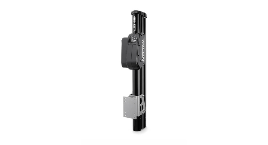
THANK YOUThank you for purchasing the Minn Kota® Talon shallow water anchor. This revolutionary shallow water anchor uses state-of-the-art technology to deliver unprecedented levels of boat control. Intuitive features and wireless control enable Talon to accurately position your boat and improve your bait presentation. Talon holds your boat in position so you can focus on fishing.REGISTRATIONRemember to keep your receipt and immediately register your Talon. To receive all the benefits of your product warranty please fill out and mail the registration card. You may also register your product online at minnkotamotors.com. SERIAL NUMBERYour Minn Kota 11-character serial number is very important. It helps to determine the specific model and year of manufacture. When contacting Consumer Service or registering your product, you will need to know your product’s serial number. We recommend that you write the serial number down so that you have it available for future reference.
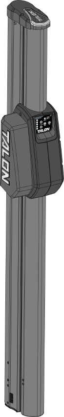
NOTICE: The serial number on your Talon is located below the motor housing.
TALON INFORMATION (For Consumer Reference Only)Model: ________________________________________________Serial Number: ___________________________________________Purchase Date: ___________________________________________Store Where Purchased: _____________________________________NOTICE: Do not return your Minn Kota product to your retailer. Your retailer is not authorized to repair or replace this unit. You may obtain service by: calling Minn Kota at (800) 227-6433; returning your Talon to the Minn Kota Factory Service Center; sending or taking your product to any Minn Kota authorized service center. A list of authorized service centers is available on our website, at minnkotamotors.com. Please include proof of purchase, serial number, and purchase date for warranty service with any of the above options.
SAFETY CONSIDERATIONS
Please thoroughly read the user manual. Follow all instructions and heed all safety considerations. Use of this product is only permitted for persons that have read and understood these instructions. Minors may use this product only under adult supervision. WARNINGYou are responsible for the safe and prudent operation of your boat or vessel, and Talon(s). This product does not relieve you from the responsibility of the safe operation of your boat. It may be hazardous to operate your Talon in rough or turbulent water conditions, such as fast currents or changing environmental conditions. Do not deploy your Talon if these conditions are present, especially when the underwater topography is unknown. Failure to follow this warning may result in unexpected operation or failure of the Talon to operate or anchor and could cause death or serious injury. You must avoid hazards to anchoring and always maintain a permanent watch so you can maintain proper control of your boat. You must always be prepared to regain manual control of your boat. Learn to operate your Minn Kota product in an area free from hazards and obstacles.WARNINGThe Talon should be disconnected from the power source when it is not in use or is off the water. When connecting the power-supply cables of the Talon to the battery or power switch, ensure that they are not kinked or subject to chafe and route them in such a way that persons cannot trip over them. Before using the Talon make sure that the insulation of the power cables is not damaged. Disregarding these safety precautions may result in electric shorts of battery(s) and/or the product. Always disconnect the Talon from the battery(s) before cleaning or checking the Talon. In the event of an unexpected operation, remove power leads from the battery. Avoid submerging the complete product as water may enter, considerable damage to the product can occur. This damage will not be covered by warranty. The constant noise pressure level of the Talon during use is less than 70dB(A). The overall vibration level does not exceed 2,5 m/sec2.WARNINGTake care that neither you nor other persons approach the Talon Spike too closely while operating, neither with body parts nor with objects. The Talon is powerful and may endanger or injure you or others. While the Talon is operating, watch out for person swimming and for floating objects. Persons who lack the ability to run the Talon or whose reactions are impaired by alcohol, drugs, medication, or other substances are not permitted to use this product.CAUTIONNever leave the boat unattended with the Talon as your only boat anchor. Talon is not intended to provide primary anchorage.WARNINGIt is recommended to only use Johnson Outdoors approved accessories with your Talon. Using non-approved accessories including those used to mount or control your roduct may cause damage, unexpected operation, and injury. Be sure to use the product and all approved accessories, including remotes, safely and in the manner directed to avoid accidental or unexpected operations. Keep all factory-installed parts in place including motor, electronic and accessory covers, enclosures, and guards. Failure to adhere to this warning may affect your warranty.
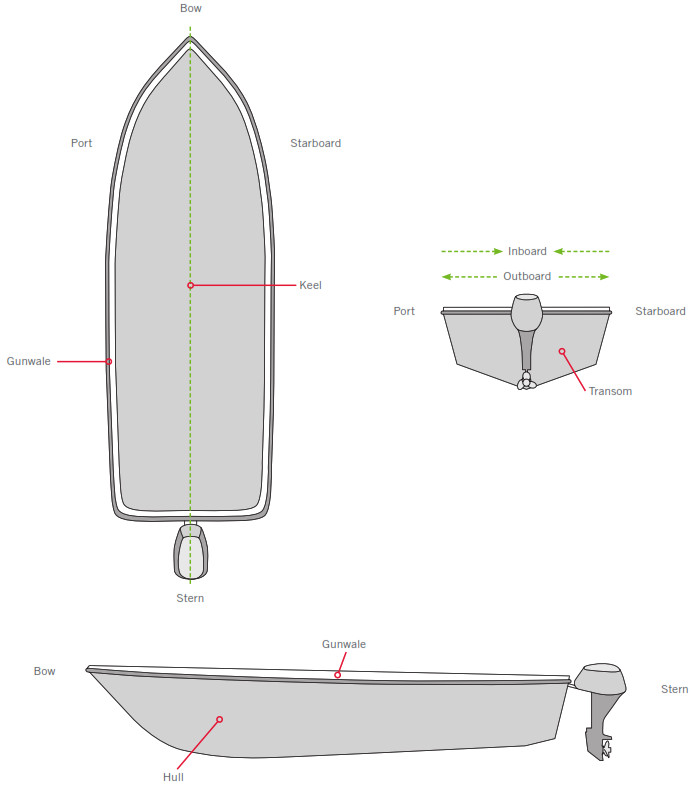
KNOW YOUR BOAT
INSTALLATION
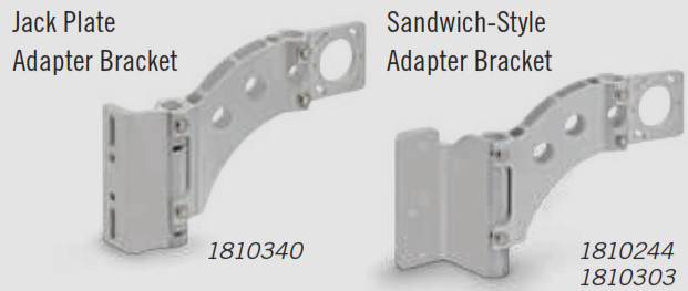
INSTALLING THE TALONYour new Talon comes out of the box with the hardware you’ll need to install it directly to the transom of your boat. If you have an irregular-shaped transom that cannot accept a direct mount, or you prefer to mount the Talon with an adapter bracket for ease of mounting and removal, please visit minnkotamotors.com for details on our Talon adapter brackets. For installation with a Talon adapter bracket, refer to the installation instructions provided with the bracket. For compatible Talon adapter brackets, to locate the nearest dealer, or for additional product support, please visit minnkotamotors.com. To install the Talon directly to the boat, please follow the directions provided in these installation instructions. Please review the parts list, mounting considerations, and tools needed for installation prior to getting started.
INSTALLATION PARTS LIST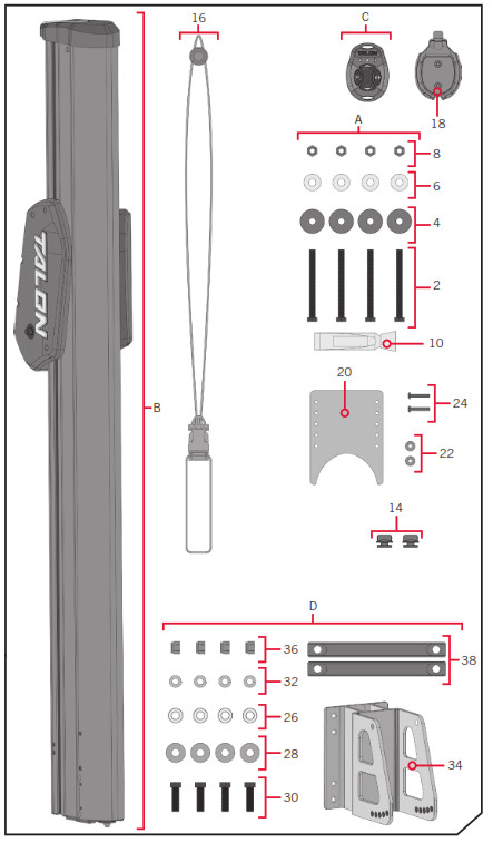
| Item /Assembly | Part # | Description | Qty. |
| A Items 2-12 | 2994903 | TALON HARDWARE BAG ASSY | 1 |
| 2 | 2373525 | BOLT-5/16-18 X 31/2″ HHCS SS | 4 |
| 4 | 2371749 | WASHER-FLAT 5/16 SS | 4 |
| 6 | 2371752 | WASHER-FENDER, 5/16, SS | 4 |
| 8 | 2223100 | NUT-5/16-18 NYLOCK S/S | 4 |
| 10 | 2378608 | ANTI SEIZE TUBE, 4CC, TALON | 1 |
| 12 | 2014802 |
BAG-ZPLCK(4×6)4ML ANTISTATIC | 1 |
| B | ✖ | TALON ASSEMBLY | 1 |
| 14 | 2372930 | CORD RETAINER | 2 |
| 16 | 2390801 | LANYARD, REMOTE | 1 |
| C | 2994150 | NEW BT TRANSMITTER ASSY | 1 |
| 18 | 2371829 | BRACKET, RMT DASH MNT HLDR | 1 |
| 20 | 2376447 | WATER SHIELD, DEFLECTOR – TALON 2 | 1 |
| 22 | 2371754 | #8 WASHER, 1/2″ OD, SS | 2 |
| 24 | 2263434 | #8-18 X 1 SS PPH | 2 |
| DItems26-38 | ✖ | MOUNTING BRACKET ASSEMBLY | 1 |
| 26 | 2371758 | WASHER-3/8 HD FLAT SS | 4 |
| 28 | 2378716 | GUARD, EXTRUSION BRACKET | 4 |
| 30 | 2383459 | SCREW-3/8-24 X 1.25 HHCS SS | 4 |
| 32 | 3391706 | WASHER-LOCK 3/8″ | 4 |
| 34 | 2378725 | BRACKET-TILT. MACH (SUB) | 1 |
| 36 | 2373138 | 3/8-24 NYLOK NUT, SS | 4 |
| 38 | 2373815 | TALON MOUNTING STRAP | 2 |
| 40 | 2377170 |
MANUAL, TALON BT | 1 |
| 42 | 2377171 |
MANUAL, INSTALL GUIDE T3 | 1 |
✖ This part is included in an assembly and cannot be ordered individually.![]() Not shown on Parts Diagram.
Not shown on Parts Diagram.
MOUNTING CONSIDERATIONSMinn Kota recommends mounting the Talon directly to the transom of the boat with the Mounting Bracket. Your Talon comes complete with all the necessary hardware to mount directly to the transom/stern. The Talon may also be mounted using an optional adapter plate when direct transom mounting is not possible or desired due to obstructions or irregular-shaped transoms. For more information on universal adapter brackets and other Minn Kota® Talon accessories, please visit minnkotamotors.com. When using an adapter bracket to mount the Talon, please use the instructions included with the accessory.
View accessories available for your Talon at minnkotamotors.com
In order to use the direct mount installation, the following conditions need to be met:
- Unobstructed Mounting – When selecting the Talon Mounting Bracket mounting location, examine your boat to ensure that you will not drill into any obstructions and that the hardware will be accessible for assembly.
- Unobstructed Deployment and Retraction – Talon is designed to mount on either the port or starboard side of the transom. Talon must have a clear, unobstructed path to deploy. Check to make sure that your proposed location will allow the anchor to deploy and retract without hitting trim tabs, poling platforms, ladders, engine or other obstructions. You should also consider your fishing methods when selecting the mounting location.
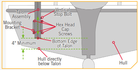
- Transom to Talon Clearance – The Talon Mounting Bracket included with your unit will allow for approximately 6″ of clearance from the transom to the front edge of the deploying anchor. When mounting the Talon Mounting Bracket directly to the transom, Minn Kota suggests installing the Mounting Bracket in the highest possible location. This will provide the most clearance and the greatest amount of vertical and angular adjustability.NOTICE: Some boats may be manufactured with a reverse transom angle. In these cases, the Talon mounting bracket may be mounted upside-down to compensate for the reverse angle.

- Talon to Hull Clearance – The bottom edge of the Talon should never be less than 4″ above the hull directly below the Talon to prevent spray and drag conditions.NOTICE: All bass boats should mount the Talon as flush with the bottom of the Talon mounting bracket as possible to mitigate spray while underway.
- Talon to Engine Clearance – When selecting a mounting location make sure that no interference exists between the Talon and your engine during normal operation. Once you have selected your mounting location, trim the engine all the way up and all the way down, and steer the engine fully to and away from the side selected. Ensure there is a minimum of two to three inches of clearance from any point on the Talon.NOTICE: In some instances, boat manufactures have begun to make hollow boat Transoms. We recommend speaking to your local boat dealer or OEM Manufacturer for mounting recommendations.
If these conditions are not met, please consider using an optional adapter plate. There are many adapter plates that allow for greater adjustability of the mount and allow for greater clearances to operate the Talon. Please visit minnkotamotors.com to learn more about selecting and installing an adapter plate.CAUTIONFollow all instructions and heed all safety considerations. Minn Kota recommends having a second person help with installation. Not following proper installation and rigging instructions may result in injury. Mounting the Talon too low can cause undue drag from the Talon or Mounting Bracket when operating the boat. It is important to mount the Talon as recommended to avoid unsafe driving conditions.TOOLS AND RESOURCES REQUIRED
| • Drill• 5⁄16″ Drill Bit• 1⁄2″ Box End or Socket Wrench• 9⁄16″ Box End or Socket Wrench• Marine Grade Sealant | • Cable Ties• Tape Measure• 30ft/lb capacity Torque Wrench• Pencil or similar marking tool• Pliers | • A second person to help with installation• Heat Shrink with Adhesive• Wire no smaller than 12AWG• Voltmeter |
INSTALLING THE TALON
INSTALL TIONInstalling the Talon
ITEM(S) NEEDED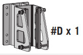
a. Review the Mounting Considerations to determine if it is acceptable to complete a direct mount of the Talon Mounting Bracket. If acceptable, position the Mounting Bracket (Item #D) at the selected location and mark the Mounting Holes with a pencil or similar marking tool. Any of the eight Mounting Holes can be used with at least one bolt in each corner of the bracket or 2 on each side.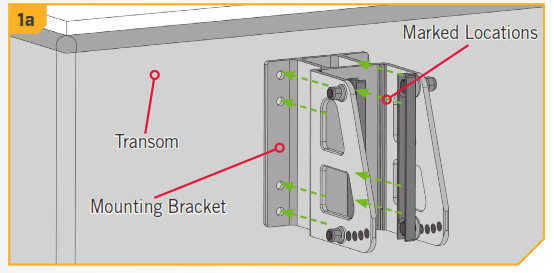 b. Double check that the mounting location is clear to drill holes and then use a Drill with a 5/16″ Drill Bit to drill through the Transom/Stern of the boat on the marked locations.NOTICE: When drilling the marked holes, make sure that the drill bit is perpendicular to the Transom/Stern of the boat and that the holes are being drilled straight. Not grilling the holes straight will give the mounting hardware a poor fit.
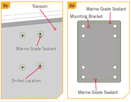
 c. Place a 1/8″ bead of Marine Grade Sealant on the Transom of the boat around the drilled holes.d. Place the Marine Grade Sealant on the face of the Mounting Bracket that will contact the boat Transom/Stern when mounted. Keep the sealant approximately centered between the outside edge of the Mounting Bracket and the Mounting Holes. Once the sealant is in place, align the Mounting Bracket in the desired orientation with the holes that were drilled in the Transom/Stern.
ITEM(S) NEEDED
e. Take each of the four 3-1/2″ Stainless Steel Bolts (Item #2) and place one Flat Washer (Item #4) on them. Place one Bolt in each of the Mounting Holes so that is passes through the Mounting Bracket and the drilled holes on the transom of the boat.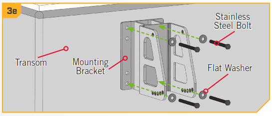 f. Place a Fender Washer (Item #6) on the end of each Bolt on the inside of the Transom and then securing each with a Nylock Nut (Item #8). Tighten the bolts with a 1/2″ Box End or Socket Wrench. Do not overtighten.NOTICE: To prevent seizing of the stainless steel hardware, do not use high-speed installation tools. Applying an anti-seize may help prevent seizing.
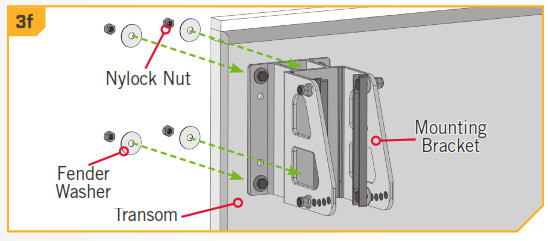
g. Once the Mounting Bracket is secured, note the Mounting Straps located on the inside of the Mounting Bracket. The Mounting Straps need to be adjusted so that they are as perpendicular as possible to the waterline. The five Angular Adjustment Holes located on one end of the Mounting Straps allow for 25 degrees of motion to accommodate the variability of different transom styles. h. If the Mounting Straps are not perpendicular, use a 9/16″ Box End or Socket Wrench to adjust the Nylock Nuts. The Bolt that passes through the Mounting Strap, opposite from the Angular Adjustment Holes should be loosened, but not removed.
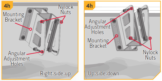 i. Next, note the position of the nuts, washers, and screws holding the Mounting Strap in place. The Hex Head Cap Screws pass from the inside to the outside of the bracket. They first pass through the Mounting Strap, then a Guard Washer, then the Mounting Bracket. On the outside of the bracket, the screw first holds a Flat Washer and then a Lock Washer before being secured with a Nylock Nut.
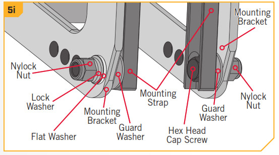 j. After the appropriate Nylock Nut has been loosened locate the Nylock Nut opposite of the loosened one on the Mounting Strap and remove it.k. Adjust the Mounting traps so that they are as perpendicular to the waterline as possible.CAUTIONDo not use the Mounting Bracket or Talon as a step to enter the boat. The bracket will be slippery when wet and is not designed to support people. Using this product as a step may result in injury.
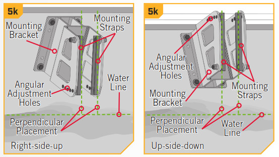 l. Once perpendicular, replace the hardware that was removed by selecting one of the five Angular Adjustment Holes that will support the Mounting Strap at the most perpendicular position.
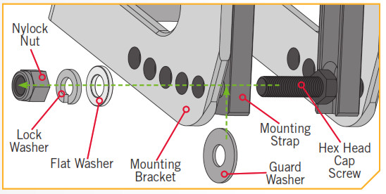 m. To replace the bolts, pass them from the inside to the outside, through the Mounting Strap, then the Guard Washer, then the Mounting Bracket, a Flat Washer, and Lock Washer. Then loosely secure with a Nylock Nut. The nuts will be fully secured later in the installation.NOTICE: To prevent seizing of the stainless steel hardware, do not use high-speed installation tools. The hardware holding the Mounting Straps in place has a pre-applied anti-seize.
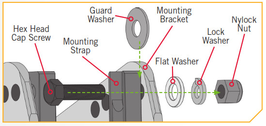 ITEM(S) NEEDED
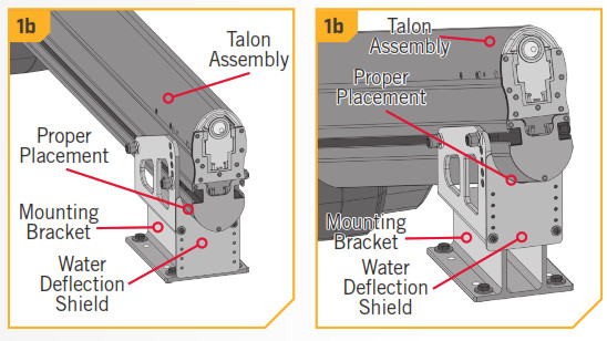
NOTICE: We recommend a second person to help with this step of the installation.n. Next the Talon Assembly should be installed on the Mounting Bracket. Take the Talon Assembly (Item #B) and notice that there is an Assembly Track located on both sides of the Talon.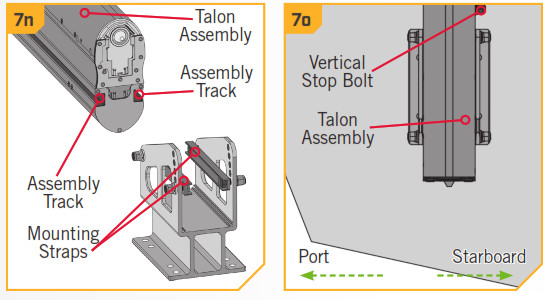 o. When the Talon is properly oriented as it would be installed, there is a single Vertical Stop Bolt located on the Starboard side of the Talon along the Assembly Track. The vertical Stop Bolt is used as a reference point or guideline to stop the Talon and position the Mounting Straps in the Assembly Track. Ensure that the Vertical Stop Bolt is secured n the approximate final position.
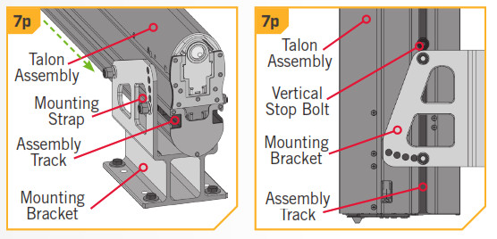 p. Carefully lift the Talon Assembly into the Mounting Bracket and align the Mounting Straps with the Assembly Track. Slide the Guard Washers to the inside wall of the Mounting Bracket, so that they sit between it and the Talon Assembly. Slide the Talon Assembly down the Assembly Tracks until it comes in contact with the Vertical Stop Bolt.
INSTALLING THE WATER DEFLECTION SHIELD
q. While supporting the Talon Assembly, adjust it and the Vertical Stop Bolt up or down in the Mounting Bracket so that the bottom of the Talon Assembly is not less than 4 inches above the bottom of the hull of the boat or the waterline of the boat. Once in place, temporarily tighten the Vertical Stop Bolt.r. Double check the placement of the Talon Assembly and make sure it meets all of the mounting considerations. Make any adjustments as necessary. When the position of the Talon Assembly is acceptable, secure the four Hex Head Cap Screws and Nylock Nuts holding the Mounting Straps in place with a 9/16″ Box End or Socket Wrench. Use a torque wrench to tighten to a recommended torque of 20 to 30 ft-lbs. Tighten the Vertical Stop Bolt.NOTICE: Additional adjustments may need to be made to the mount after a trial run with the boat on the water. Periodically re-tighten the four nuts and screws to 20 to 30 ft-lbs.
CAUTIONCheck tension of the 4 vertical adjustment nuts after initial use and periodically thereafter to ensure they are at the recommended torque of 20 to 30 ft-lbs.
Installing the Water Deflection ShieldThe Water Deflection Shield is designed to prevent undesirable spray conditions while the boat is traveling over water. The Water Deflection Shield is installed after the Talon is successfully installed on the boat. Each installation will be different and is dependent upon the position of the Talon as it sits in the Mounting Bracket. The Water Deflection Shield is installed on the bottom side of the Mounting Bracket as it is attached to the boat. The installation is designed to be adjustable to suit different angular positions.
ITEM(S) NEEDED
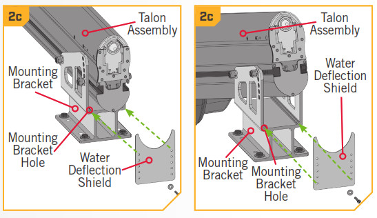
a. Make sure that the Talon is positioned as recommended and installed properly by reviewing the Installing the Talon section of this manual.b. Once complete, take the Water Deflection Shield (Item #20), and determine where it will be installed on the Mounting Bracket. When placed properly, the curved edge of the hield will sit against the surface of the Talon Assembly that sits inboard in the Mounting Bracket.
c. Align the closest set of holes in the shield with the holes in the bottom of the Mounting Bracket. The set of holes used on the shield will vary for each individual installation.NOTICE: The Water Deflection Shield will always be installed on the bottom side of the Mounting Bracket regardless of the orientation that the Mounting Bracket was installed. There should be no gap between the shield and the Talon.
ITEM(S) NEED![]()
d. Take two each of the 1/2″ Washers (Item #22) and two of the 1″ Phillips Pan Head Screws (Item #24) to attach the shield to the Mounting Bracket. Place one washer on each of the screws. The screw should pass through a washer, then the Water Deflection Shield, and into the Mounting Bracket. Secure the screws using a #2 Screwdriver. NOTICE: To prevent seizing of the stainless steel hardware, do not use high-speed installation tools. Applying an anti-seize may help prevent seizing.NOTICE: If you adjust the angle of your Talon after this step is complete, you will need to re-adjust the placement of the Water Deflection Shield to ensure proper functionality.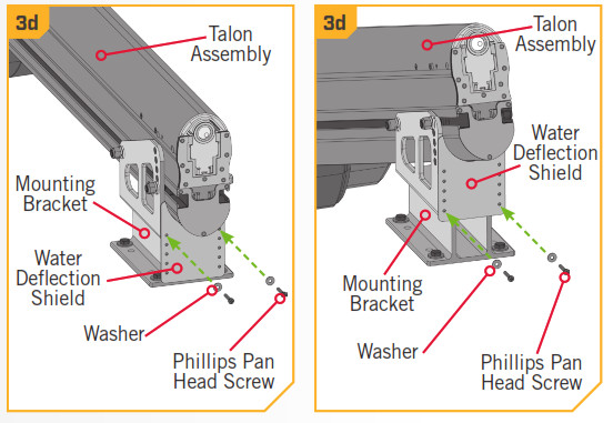
INSTALLING THE POWER CABLE AND DEPLOYMENT NOTIFICATION ALARM WIRE
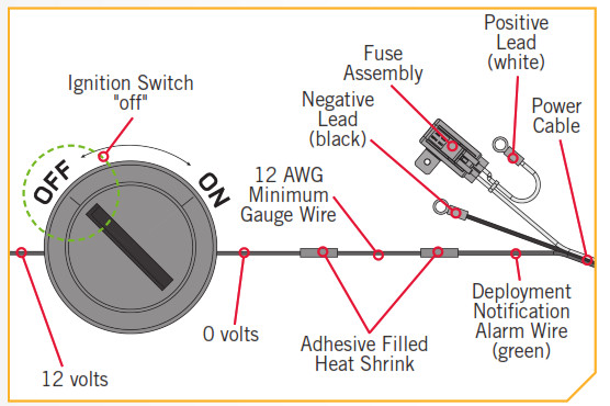
The Talon Power Cable consists of a 30 amp in-line resettable fuse on the positive lead, a negative lead, and a Deployment Notification Alarm Wire. The Deployment Notification Alarm Wire is a green wire that comes from the Power Cable and, when installed, is used to sound an alarm, when the Ignition Switch is turned to the “on” position with the Talon deployed. When connected and the Talon is properly stowed, no tone will be emitted when the Ignition Switch is turned “on”. Minn Kota recommends connecting the Power Cable to the starting battery through a battery selector/power disconnect switch. The Talon does draw a small amount of residual current fromthe battery even when not in use. By connecting the positive lead of the Talon Power Cable through a battery selector/power disconnect switch it will disconnect power to the Talon when the Power Switch is “off”. The Power Switch must have a minimum amp rating of 60amps per Talon. If you are not connecting the Talon to a battery selector/power disconnect switch, it can be connected directly to the starting battery but should be disconnected from power when the Talon is not in use. The Power Cable can be routed in a number of different ways depending on a boat’s unique setup. It is recommended to route the Power Cable using the shortest and cleanest route from the Talon to the battery connection. Please see the Battery & Wiring Installation section of this Manual for more information.NOTICE: It is not necessary to connect the Deployment Notification Alarm Wire in order for the Talon to function, but it is needed to comply with warranty requirements.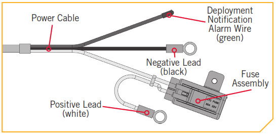 a. Inspect the selected wire routing and make sure that there are no sharp edges, obstacles, or obstructions that may damage the Power Cable. If routing along with the gas outboard ire or a cable harness assembly, you may need to open any wire ties or clamps to allow the Power Cable to pass through.b. Carefully route the Power Cable along the intended path. Remove any slack in the Power Cable so that it routes without any bulges, lumps or kinks. c. The Power Cable for the Talon splits at the end to include the positive lead with a fuse, a negative lead, and then the Deployment Notification Alarm Wire. If you choose not to connect the Deployment Notification Alarm, skip stepping 4.
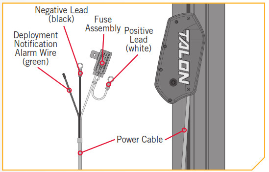 NOTICE: If unsure of how to wire the Talon Power Cable, please see a qualified marine technician.d. The optional Deployment Notification Alarm will be connected to the side of the 12-volt Ignition Switch that lacks power when the switch is turned “off”. Use a voltmeter to determine where this connection exists. You may need to turn the Ignition Switch “on”and “off” to verify this connection with the voltmeter. 12 volts should be present at the connection when the ignition switch is turned to the “on” position and no voltage should be present when the switch is turned to the “off” position.
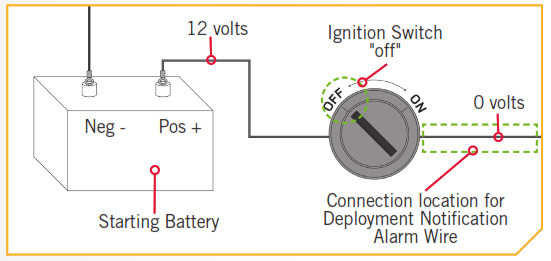 e. Next determine if the Deployment Notification Alarm Wire is long enough to reach the intended connection. If additional wire is needed, use a wire that is no smaller than 12 WG.
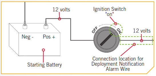 f. Be sure that the Ignition Switch is turned to the “off” position. Cut off the sealed end of the green Deployment Notification Alarm Wire on the Power Cable and splice it to the 12 AWG minimum gauge wire, or if there is enough slack in the wire, directly to the switched side of the Ignition Switch that was just tested. Use an adhesive-filled heat shrink to waterproof and secure the splice.g. If an additional wire was used, close the final connection between the Ignition Switch and the additional 12 AWG wire and seal with an adhesive-filled heat shrink.NOTICE: When properly installed the alarm will only sound when the ignition key is turned on when the Talon is not fully retracted.
h. If connecting to an optional battery selector/power disconnect switch, turn it to the “off” position before connecting the Power Cable.i. The positive white lead wire coming from the Power Cable has a red band and contains the Fuse Assembly. This wire connects to the Starting Battery positive (+) terminal or the battery selector positive. Connect the black negative lead of the Power Cable to the Starting Battery negative (-) terminal. If additional wiring needs to be used to make the connections, please see the Battery and Wiring Installation Section of this manual. Secure any splices with an adhesive-filled heat shrink tube. Make sure that the Fuse Assembly is used.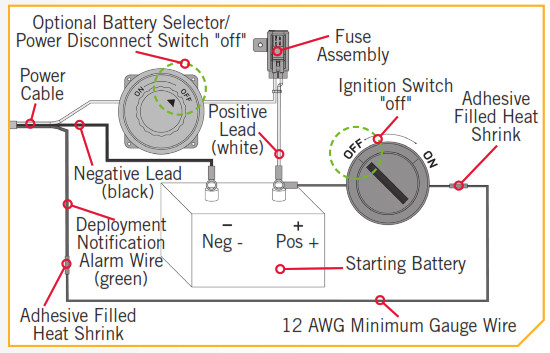 NOTICE: For proper American Boat & Yacht Council Compliance, if the Fuse Assembly is removed, the user must install a 30 amp fuse within 7″ of the positive battery terminal (+).
ITEM(S) NEEDED![]() j. Once the Power Cable has been routed, connected, and secured, the remaining loose cable may be pushed inside the Assembly Track that runs vertically along the outside column of the Talon.NOTICE: Depending on your wiring, there may be more or less slack in the Power Cable. The Cord Retainer’s use and placement will vary from installation to installation.k. Take the two Cord Retainers (Item #14) and push the t-slot portion of them into the Assembly Track. Once positioned use a pair of pliers to turn the Cord Retainer 90 degrees in the Assembly Track to lock it in place.
j. Once the Power Cable has been routed, connected, and secured, the remaining loose cable may be pushed inside the Assembly Track that runs vertically along the outside column of the Talon.NOTICE: Depending on your wiring, there may be more or less slack in the Power Cable. The Cord Retainer’s use and placement will vary from installation to installation.k. Take the two Cord Retainers (Item #14) and push the t-slot portion of them into the Assembly Track. Once positioned use a pair of pliers to turn the Cord Retainer 90 degrees in the Assembly Track to lock it in place.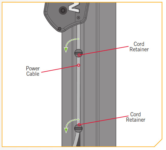
VERIFYING INSTALLATION
Once installation is complete, use the following procedure to verify installation and confirm your Talon is ready to use.
a. For this test your Talon must be able to deploy and make contact with the ground without hitting any obstructions. Carefully inspect the area around the Talon for any obstructions that may interfere with deployment.b. If using a battery selector, or power disconnect switch, turn the selector switch to the “on” position. On the Indicator Panel of the Talon are three buttons needed for this verification, the Up![]() button, the Down
button, the Down ![]() button, and the Mode
button, and the Mode ![]() button. Press the mode
button. Press the mode ![]() button until the Mode LED is unlit.
button until the Mode LED is unlit.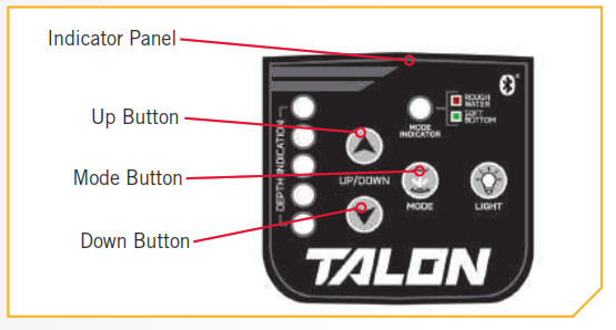 c. Stand clear of the Talon and push the Down
 ![]() button. The Talon spike will begin to deploy. The Depth Indication LEDs on the Indicator Panel will track the progress of the talon as the Spike deploys.d. When the Spike comes in contact with the ground, the unit will automatically shut off. After the initial shut-off, you will hear two (2) additional deploy cycles (or clicks), each 3-seconds apart from the initial ground contact.e. If the Talon functions as described above, press the Up
button. The Talon spike will begin to deploy. The Depth Indication LEDs on the Indicator Panel will track the progress of the talon as the Spike deploys.d. When the Spike comes in contact with the ground, the unit will automatically shut off. After the initial shut-off, you will hear two (2) additional deploy cycles (or clicks), each 3-seconds apart from the initial ground contact.e. If the Talon functions as described above, press the Up ![]() button. The Talon will fully retract. If the talon does not function as described, double-check all wiring connections and verify proper polarity to white and black power leads, and retest.NOTICE: To perform the same test using the remote instead of the buttons on the Indicator Panel, use the Anchor Mode
button. The Talon will fully retract. If the talon does not function as described, double-check all wiring connections and verify proper polarity to white and black power leads, and retest.NOTICE: To perform the same test using the remote instead of the buttons on the Indicator Panel, use the Anchor Mode ![]() button, the Up
button, the Up![]() button, and the Down
button, and the Down![]() button on the remote. To deploy the anchor on the remote, the Down
button on the remote. To deploy the anchor on the remote, the Down ![]() button must be double pressed.
button must be double pressed.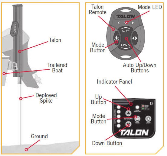
BATTERY & WIRING INSTALLATION
BOAT RIGGING & PRODUCT INSTALLATIONFor safety and compliance reasons, we recommend that you follow American Boat and Yacht Council (ABYC) standards when rigging your boat. Altering boat wiring should be completed by a qualified marine technician. The following specifications are for general guidelines only.CAUTIONPlease read the following information before connecting your Talon(s) to your battery in order to avoid damaging your product and/or voiding your warranty.CAUTIONThese guidelines apply to general rigging to support your Minn Kota product. Powering multiple Talons or additional electrical devices from the same power circuit may impact the recommended conductor gauge and circuit breaker size. If you are using wire longer than that provided with your unit, follow the conductor gauge and circuit breaker sizing table below. If your wire extension length is more than 25 feet, we recommend that you contact a qualified marine technician.CAUTIONAn over-current protection device (circuit breaker or fuse) must be used. Coast Guard requirements dictate that each ungrounded current-carrying conductor must be protected by a manually reset, trip-free circuit breaker or fuse. The type (voltage and current rating) of the fuse or circuit breaker must be sized accordingly. The table below gives recommended guidelines for circuit breaker sizing.CONDUCTOR GAUGE AND CIRCUIT BREAKER SIZING TABLEThis conductor and circuit breaker sizing table is only valid for the following assumptions:
- No more than 2 conductors are bundled together inside of a sheath or conduit outside of engine spaces.
- Each conductor has 105° C temp-rated insulation.
- No more than 5% voltage drop allowed at full power based on published product power requirements.
| Wire Extension Length | ||||||
| Max Amp Draw | Circuit Breaker | 5 feet | 10 feet | 15 feet | 20 feet | 25 feet |
| 30 Amps | 30 Amp @ 12 VDC | 10 AWG | 10 AWG | 8 AWG | 6 AWG | 4 AWG |
NOTICE: Wire Extension Length refers to the distance from the batteries to the Talon leads. Maximum Amp Draw values only occur intermittently during select conditions and should not be used as continuous amp load ratings.ReferenceUnited States Code of Federal Regulations: 33 CFR 183 – Boats and Associated Equipment ABYC E-11: AC and DC Electrical Systems on Boats
SELECTING THE CORRECT BATTERIES
The Talon will operate with any lead-acid, marine 12-volt battery. For best results, Minn Kota recommends connecting to the starting battery. Maintain battery at full charge. Proper care will ensure having battery power when you need it, and will significantly improve the battery life. Failure to recharge lead-acid batteries (within 12-24 hours) is the leading cause of premature battery failure. Use a multistage charger to avoid overcharging. We offer a wide selection of chargers to fit your charging needs. For more information on battery selection and rigging, please visit minnkotamotors.com.The Talon draws a small amount of residual current from the battery even when not in use. If the Talon will not be used for more than 5 days, the Talon power leads should be disconnected from the battery. Avoid connecting the Talon to the same batteries that a trolling motor or other accessories are connected to. It is recommended the Talon be connected to the Starting Battery through a battery selector or power disconnect switch. This will disconnect power to the Talon when the Power Switch is “off”. If you are not using a battery selector/power disconnect switch, the Talon may be connected directly to the Starting Battery.WARNINGNever connect the (+) and the (–) terminals of the same battery together. Take care that no metal object can fall onto the battery and short the terminals. This would immediately lead to short and extreme fire danger.For proper ABYC compliance, when the factory fuse has been removed, the user must install a 30A fuse within 7″ of the positive battery terminal.NOTICE: The in-line re-settable 30A fuse is designed to protect the system. If this fuse repeatedly trips, faulty wiring could bethe cause and must be corrected. If the re-settable fuse itself is suspect, Minn Kota recommends contacting customer service for aproper replacement.CONNECTING THE BATTERIES12 Volt Systems
- If connecting to an optional battery selector/power disconnect switch, turn it to the “off” position prior to connecting the power cable.
- Connect positive ( + ) white lead to positive ( + ) battery terminal, or switch positive.
- Connect negative ( – ) black lead to negative ( – ) battery terminal, or switch negative.
WARNINGObserve proper polarity and follow instructions in your boat owner’s manual regarding polarity.
WARNING
- The Talon draws a small amount of residual current from the battery even when not in use. If the Talon is not be used for more than 5 days, or while the battery/batteries are being charged, the Talon power leads should be disconnected from the battery. It is recommended the Talon be connected to the Starting Battery through a battery selector or power disconnect switch. This will disconnect power to the Talon when the Power Switch is “off”. If you are not using a battery selector/switch, the Talon may be connected directly to the starting battery.
- Keep lead wire connections tight and solid to the battery or switch terminals.
- The Starting Battery should be located in a ventilated compartment to avoid sparks from combustible materials.
THIS COMPLETES THE INSTALLATION OF YOUR TALON. A COMPLETE OWNER’S MANUAL CAN BE DOWNLOADED AT MINNKOTAMOTORS.COM.
NOTES____________________________
__________________________
__________________________
RECOMMENDED ACCESSORIES
ON-BOARD & PORTABLE BATTERY CHARGERSStop buying new batteries and start taking care of the ones you’ve got. Many chargers can actually damage your battery over time – creating shorter run times and shorter overall life. Digitally controlled Minn Kota chargers are designed to provide the fastest charge that protects and extends battery life.

TALON ACCESSORIES
UNIVERSAL MODULAR ADAPTER BRACKETSIt’s easy to choose your bracket, easy to install it and pretty much impossible for anything to stop it. Talon’s Universal Modular Adapter Brackets are built stronger than they have to be, and their innovative modular design lets you put Talon in just the right position on your boat.
Unparalleled StrengthWe built Talon with uncompromising power. And we built the brackets the exact same way. Made with extruded aluminum and reinforced with rugged construction, our brackets hold Talon steady whether you’re trailering or tearing through heavy chop.
TALON TILT BRACKETThis marine-grade, anodized aluminum tilt bracket accommodates low-clearance areas and boat storage. Features adjustable deck support for added stability while tilting.
Universal Modular DesignTwo brackets. Any transom. The universal design fits any situation, and the brackets can be adjusted and tweaked to the perfect orientation. Two pivot points let you adjust Talon to the perfect orientation (based on your transom style, outboard location, and other factors). Once it’s in position, interlocking teeth clamp down to lock it into place.


![]()

Minn Kota Consumer & Technical ServiceJohnson Outdoors Marine Electronics, Inc.PO Box 8129Mankato, MN 56001
121 Power Drive Mankato, MN 56001Phone (800) 227-6433Fax (800) 527-4464

©2021 Johnson Outdoors Marine Electronics, Inc.All rights reserved.
References
[xyz-ips snippet=”download-snippet”]