
MINN KOTA Trolling Motor Plus and Receptacle
Parts

TOOLS AND RESOURCES REQUIRED
- Wire Stripper
- Pencil or marking tool
- Wire Cutter
- Ruler
- 3/32″ Allen Wrench
- Heat Gun
- Marking Tool
- Drill
- 1-¾” Hole Saw
- 1/8″ Drill Bit
- Phillips Screw Driver
MOUNTING CONSIDERATIONS
Before installing your Trolling Motor Plug and Receptacle, please give consideration to the following:
- The mounting surface needs to have a flat surface no less than 3-¼” wide x 2-½ inches high. Use the Face Plate (Item #2) to check for clearance at the desired mounting locationWARNING: Make sure the power source is disconnected or, if controlled by a switch, turned OFF before beginning installation of the Plug Receptacle. Failure to remove power from the Boat Wires could cause electric shock.NOTICE: If uncomfortable making this installation, we recommend to have the Motor Plug and Receptacle installed by a qualified marine installer.WARNING: Do not tin any wires with this installation. Tinned wires could cause the connection to loosen over time, creating an improper connection. Improper connections could cause a short or extreme fire danger. Follow the installation instructions provided to avoid product failure and injury.
- Make sure the area under the mounting location is clear to drill holes and that installation hardware will not damage existing components or wiring below the mounting surface.
- Make sure that the trolling motor Power Leads and the Boat Wires are not connected to a power source before beginning installation.
- Test that the Boat Wires can reach the intended mounting location to be attached to the Plug Receptacle. Also check that the Trolling Motor Lead Wires can reach the Plug Assembly wires and that there is enough slack that the plug can be both plugged in and unplugged at the intended location. All wires should not only reach, but also have extra slack to allow for ease of installation or repairs and relieve tension on the final installation. If the wires are not adequate in length, select another location.
- Determine if the mounting location will work when the Plug Assembly is plugged into the Plug Receptacle. Check for clearance that will be required for the cords exiting and entering on both sides of the installation. Allow for space for the cords to exist and accommodate plugging and unplugging the plug as needed.
INSTALLATION
Trolling Motor Plug and Receptacle Installation
a. Review the Mounting Considerations and determine an acceptable Mounting LocationWARNING: Make sure the power source is disconnected or, if controlled by a switch, turned OFF before beginning installation of the Plug Receptacle. Failure to remove power from the Boat Wires could cause electric shock.
b. Once an acceptable Mounting Location is selected, remove any power leading to the Boat Wires. Use a Drill with a 1-¾” Hole Saw to drill a hole through the selected location.c. With the hole drilled, locate the Boat Wires that the plug will be connected to. The wires may need to be trimmed and stripped. Use a Wire Cutter to cut the wires to remove any terminals or covers that may be in place.
NOTICE: For ease of installation, it is recommended to stagger the ends of the wires by 1-¼”. Make the Negative (-) Boat Wire the shorter wire of the two. Staggering the length of the wires will help with the installation of the hardware used to connect the wires later in the installation.
NOTICE: The ends of the Boat Wires may have any sort of electrical connector that should be removed.
d. With a Wire Stripper remove the protective covering on the wires. It is recommended to remove approximately ½” to ¾” of the protective covering to expose the wires. Use a Ruler to measure this distance if necessary. If the Positive (+) and Negative (-) Boat Wires are fused together, split them so they are separated by a minimum of 2-½” from the end of the shortest wire.
e. Take the Boat Wires and fish them through the 1-¾” hole that was cut in the Mounting Location. The wires should pass from the back so that the newly trimmed ends exit the front of the hole.
f. The Boat Wires that were stripped will be covered with a 6 AWG Ferrule (Item #14) to contain the wire strands. Take the two Ferrules and place one at the end of each wire, encasing all of the wire strands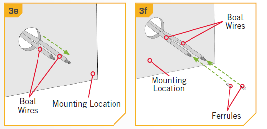 NOTICE: The 6 AWG Ferrule are the largest in the provided hardware. The four 8 AWG Ferrules may only be needed if the Plug Receptacle or Plug Assembly wires need to be trimmed or recapped.
NOTICE: Boat Wire sizes vary, so it may be necessary to use a different sized Ferrule.
g. With the wires out the front of the Mounting Location, take one of the 2” Shrink Tubes (Items #6) and place one on the end of the longer Positive (+) Boat Wire.
h. Take one Splicer (Item #12) and place it on the end of the Positive (+) Boat Wire. The Splicer is secured to the Boat Wire over the Ferrule. Secure the Splicer by tightening the Set Screw with an 3/32″ Allen Wrench to 20 in-lbs.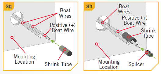 i. The Splicer and Shrink Tube should be added to the Plug Receptacle so it can be attached to the Boat Wires. Take the Plug Receptacle (Item #B) and place one Shrink Tube (Item #6), followed by one Splicer (Item #12) on the end of the black Negative (-) Wire of the Plug Receptacle. Secure the Splicer by tightening the Set Screw with a 3/32″ Allen Wrench to 20 in-lbs
NOTICE: The positive (+) and negative (-) wires on the Plug Receptacle should have Ferrules already applied.
j. Take the Plug Receptacle and identify the red Positive (+) Wire on the Plug Receptacle and align it with the Positive (+) Boat Wire. Insert it into the Splicer at the end of the Positive (+) Boat Wire. Take the black Negative (-) Wire from the Plug Receptacle and align it with the Negative (-) Boat Wire. Insert it in the Splicer at the end of the black Negative (-) Wire of the Plug Receptacle. Secure the Set Screw of both Splicers with the Allen Wrench to 20 in-lbs.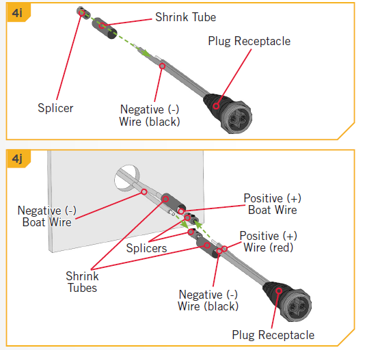 k. Once the Splicers are secure on both wires, take the Shrink Tubes and slide them over the Splicers. The Shrink Tube should be centered over the Splicer and completely cover the wire connections.
l. When satisfied with the position, secure the Shrink Tubes in place with a Heat Gun. Ensure that there is no opening around the Shrink Tubes when heated. Push the wires and the Plug Receptacle into the drilled hole until the Plug Receptacle sits against the mounting surface.
NOTICE: The Shrink Tubes are meant to water proof the connection between the Plug Receptacle and the Boat Wires. Make sure there are no gaps around the wires that would allow water to reach the connection.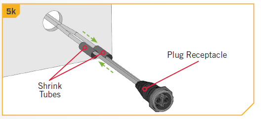
m. The Face Plate (Item #2) is designed to be keyed with the Plug Receptacle. Turn the Face Plate over and notice the notches along the Inner Circle. These notches are keyed with the outer edge of the Plug Receptacle when it sits flush on the mounting surface. This allows the Face Plate or Plug Receptacle to be rotated in 45 degree increments.
NOTICE: Tethering the Dust Cap to the Face Plate during installation is optional. The Dust Cap can be stowed away when the plug is in use and should be replaced for storage or transport.
n. On the back side of the Face Plate, there is also a hook to attached the Dust Cover (Item #C). Determine if the Dust Cover will hang to the right or the left and turn the hook on the Face Plate to the appropriate direction.
o. Flip the Face Plate so the keys on the Inner Circle are towards the mounting surface and place it over the Plug Receptacle. It should be seated on the mounting surface.
p. Take the Plug Assembly (Item #A) and plug it into the Plug Receptacle. The Plug Assembly and Plug Receptacle are also keyed with each other. Orientate the Plug Assembly and Plug Receptacle so they can be fully pushed together. The Threaded Collar on the Plug Assembly does not have to be tightened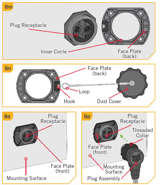
NOTICE: Use the Dust Cap when plug is not in use to insure optimal water tight protection to electrical contacts.
 t. With pilot holes drilled, push the wires, Face Plate and Plug Receptacle back in place on the Mounting Surface.
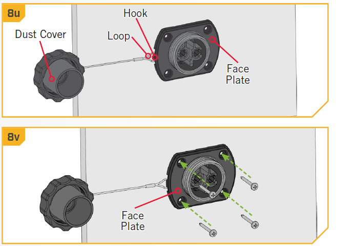 w. Locate the Power Leads for the trolling motor. Turn the power on the motor “off” and remove the motor Power Leads from any power source.
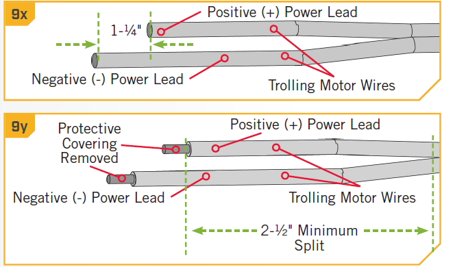 z. Both the Positive (+) Power Lead and Negative (-) Power Lead of the Trolling Motor Wires should be covered with a Ferrule. Take two 10 AWG or 8 AWG Ferrules (Item #18) or (Item #16) and place one on the end of each of the motor wires. With the Ferrules placed, take the Splice Cover (Item #4) and thread both the Positive (+) and Negative (-) Power Lead of the Trolling Motor Wires through it.
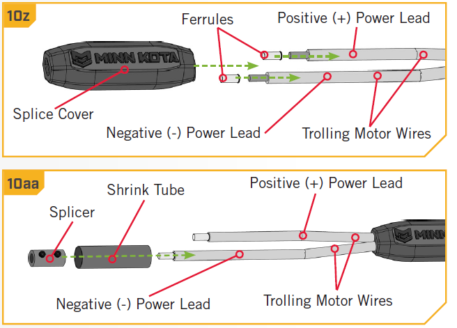 ab. The Splicer and Shrink Tube should be added to the Plug Receptacle so it can be attached to the Boat Wires. Take the Plug Receptacle (Item #B) and place one Shrink Tube (Item #6), followed by one Splicer (Item #12) on the end of the black Negative (-) Wire of the Plug Receptacle. Secure the Splicer by tightening the Set Screw with a 3/32″ Allen Wrench to 20 in-lbs.
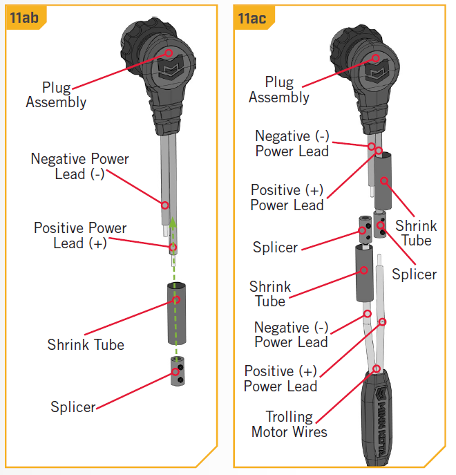
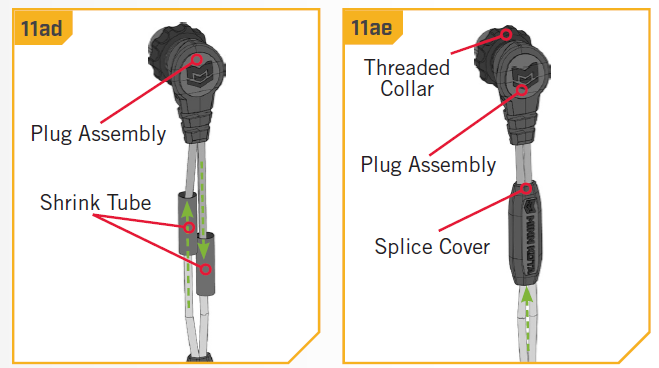 NOTICE: When connecting the plug assembly from the receptacle, be sure to tighten the Threaded Collar to ensure a proper water tight seal is achieved to protect electrical contacts. Failure to tighten the Threaded Collar could result in water intrusion.
[xyz-ips snippet=”download-snippet”]