
ML Accessories OP2 Weatherproof Switch

GENERAL INSTRUCTIONS
These instructions should be read carefully and retained after installation by the end user for future reference and maintenance. These instructions should be used to aid installation of the following products: OP2 / OP3 / OP21
SAFETY
- This product must be installed in accordance with the latest edition of the IEE Wiring Regulations (BS7671) and current Building Regulations. If in any doubt, consult a qualified electrician
- Please isolate mains prior to installation or maintenance
- Check the total load on the circuit (including when this product is fitted) does not exceed the rating of the circuit cable, fuse or circuit breaker
- Please note the IP (Ingress Protection) rating of this product when deciding the location for installation
- Do not overload this accessory or subject it to conditions outside its rating
- This product is Class II double insulated
- This product is IP66 rated
INSTALLATION
Please note: the unit should be fixed to a rigid flat surface as unevenness could cause damage to the product or affect operation
- Provide power to the required point of installation (refer to BS7671 for correct cabling methods)
- Remove the front assembly from the backbox and carefully lift off the gasket. Drill the required number of fixing holes into the backbox (see Fig. 1)
 (Fig.1)
 - Using the backbox as a template, mark the location for, and drill the fixing holes ensuring not to infringe with any gas/water pipes or electrical cables. The backbox can be rotated through 180° if required to position the two cable entries on the top
- The backbox has drain hole drilling guides marked (see Fig. 2). Drilling a drain hole is advised if the unit is installed in a location subject to temperature fluctuations where build-up of condensation may occur. It is not advised if the unit will be subject to spray or jets, as drilling a drain hole will reduce the IP rating. A 3-5mm hole can be drilled at the bottom back edge of the enclosure where marked. If wiring in conduit to the bottom entry, the drain hole should be drilled at the lowest point of the conduit run and not in the backbox(Fig.2)
 (Fig.1)
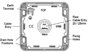 (Fig.2)
- Remove one or more of the pre-fitted blank plugs as required by pushing out from the inside and install a suitable IP rated gland or adaptor (not supplied). For rear entry; cut or drill a 20/25mm hole where marked and install a suitable IP rated grommet (not supplied). Unused cable entries must have the blank plugs fitted
- Feed the mains cables into the unit and secure the baseplate to the surface. The fixing holes are slotted to allow some rotational adjustment
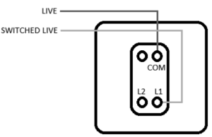
- Replace the gasket onto the backbox, then carefully wire as shown in Fig. 3(Fig.3)
- Replace the gasket onto the backbox, then carefully wire as shown in Fig. 3 (one-way operation) or is observed(Fig.4)
- Terminate any earth conductors into the earth terminal in the backbox. Use green/yellow sleeving on earth conductors that are not insulated
- Wire the LED indicator as required (see Power Indicator Wiring below)
- Check all electrical connections are secure with no loose strands of cable
- Ensuring the gasket does not become damaged or pinched, fit the switch assembly onto the backbox, taking care not to compress, damage, or trap any cables, and secure with the screws provided – do not overtighten
- Fit screw covers
- Switch on and check for correct operation
 (Fig.3)
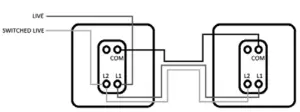 (Fig.4)
POWER INDICATOR WIRING
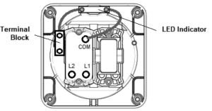
The unit has a Power Indicator pre-wired between the COM terminal and a terminal block on the rear of the faceplate.
(Fig.5)
The Power Indicator can be wired in one of three ways. Each of these options requires access to a Neutral supply.
- Power Mode: LED ON when power is ON
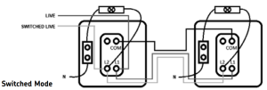
- Switched Mode: LED ON when switch is ON
- Locator Mode: LED ON when switch is OFFNote: for the 2G switch OP3, the LED Power Indicator can only be wired to work with one switch, it cannot operate with both switchesPower Mode: connect the supply Neutral to the terminal block (see Fig. 6)(Fig.6)
Note: when the switch is wired for two-way operation, the Power Indicator LED must be connected to the L1 terminal instead of the COM terminal (see Fig. 9
Switched Mode: connect the supply Neutral to the terminal block; disconnect the Power Indicator LED from the COM terminal and connect instead to the L1 terminal (see Fig. 7)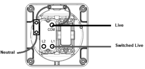 (Fig.7)
Note: when the switch is wired for two-way operation, the Power Indicator LED must be connected to the L2 terminal instead of the L1 terminal (see Fig. 10)
Locator Mode: connect the supply Neutral to the terminal block; disconnect the Power Indicator LED from the COM terminal and connect instead to the L2 terminal (see Fig. 8)(Fig.8)
Note: this option is not possible when the switch is wired for two-way operation and is not possible with OP21
Two-way operationWhen the switch is wired for two-way operation, the Power Indicator LED Wiring is as follows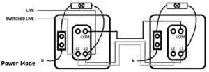 (Fig.9)
 (Fig.10)
WARNING
This product must be disconnected from the circuit if subjected to any high voltage or insulation resistance testing. Irreparable damage will occur if this instruction is not followed.
GENERAL
This product should be recycled in the correct manner when it reaches the end of its life.Check local authorities for where facilities exist.Clean the external surfaces with a damp cloth using a mild solution of detergent and warmwater only, do not use aggressive cleaning products or solvents which may damage the product.Do not use any source of high-pressure washers to maintain or clean this product.
WARRANTY
This product has a warranty of 1 years from date of purchase. Failure to install this product in accordance with the current edition of the IEE Wiring Regulations (BS7671), improper use, or removal of the batch code will invalidate the warranty. If this product should fail within its warranty period, it should be returned to the place of purchase for a free of charge replacement. ML Accessories does not accept responsibility for any installation costs associated with the replacement product. Your statutory rights are not affected. ML Accessories reserve the right to alter product specification without prior notice.


ML Accessories Limited LU5 4LTwww.mlaccessories.co.uk
References
[xyz-ips snippet=”download-snippet”]