
INSTALLATION
Models: MA-CAM33 Camera Controller Radio Accessory
Overview:
The MA-CAM3 is a 12volt DC video switcher that will support (3) cameras. Typically a car stereo with an LCD display will have an input for only (1) backup camera. To provide maximum safety, this three-camera controller will support additional Left and Right cameras. In an RV application, 3 cameras are critical for maximum safety.
Power and Trigger Wire Harness:
Red Wire: Connect the RED wire to +12 volts supplied by the ignition key. Power should only be applied when the vehicle’s ignition key is in the RUN position.Black Wire: Connect the BLACK wire to ground. Locate a screw or small bolt that is part of the vehicle frame to provide a good ground. If no screw or bolt is available, Drill a 1/8” hole into the metal structure and use a self-tapping screw to secure the BLACK wire.White Wire: Connect the WHITE wire to the (+) wire on the LEFT turn signal light. Check the wire with a voltmeter. The wire should pulse +12 volts when the left turn signal is active.Blue Wire: Connect the BLUE wire to the (+) wire on the Right turn signal light. Check the wire with a voltmeter. The wire should pulse +12 volts when the right turn signal is active.Yellow Wire: Connect the YELLOW wire to the (+) wire on the reverse light. Check the wire with a voltmeter. The wire should indicate +12 volts when the vehicle transmission is placed in reverse.
Video Output Harness:
Yellow RCA Connector: Connect the Yellow RCA connector to the “Rear Camera” or “Backup Camera” video input of the car stereo system. This cable provides video from the cameras to the input on the radio.
Red Wire: The RED wire provides +12 power to the “Reverse Trigger Input” of the car stereo when the WHITE, BLUE or YELLOW wires are active. Connect the RED wire to the (+) power input on the car stereo marked “Reverse or Backup Trigger” See the wiring instructions provided with the car stereo.
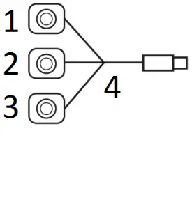
Camera Input Connections:
The MA-CAM3 controller has inputs for (3) cameras. Each camera cable provides (2) connections. Place the cable connectors into the ports that are related to the cameras position on the vehicle.
Yellow RCA Connector: Connect the YELLOW RCA connector to the video output of a camera.
Red Wire: The RED wire provides +12 volts to power on the camera. Connect the RED wire to the camera +12volt power input wire. Connect the camera ground wire to ground (Vehicle Frame Ground).
Function:
1. At all times when the ignition key is on, the rear-view camera will be displayed on the radio display. This feature is typical to RV use as many RV vehicles will have a vehicle in tow or have equipment or recreational vehicles attached to the rear of the vehicle.
Note: Not all car stereos will allow camera monitoring on the radio screen while another source is playing. Check your radio’s Owner’s Manual.
2. When the LEFT turn signal is active, the radio display will switch to the LEFT side view. The LEFT camera view will be displayed while the turn signal control is active.
3. When the RIGHT turn signal is active, the radio display will switch to the RIGHT side view. The RIGHT camera view will be displayed while the turn signal control is active.
4. When the vehicle’s transmission is placed in the reverse gear mode, the radio display will switch to the REAR camera view. The REAR camera view will be displayed while the vehicle’s transmission is in reverse gear mode.
See Reverse Side for Installation Diagrams
Typical 3 Camera Installation
- REVERSE CAMERA
- LEFT CAMERA
- RIGHT CAMERA
- IGNITION SWITCH
- RIGHT TURN BULB
- LEFT TURN BULB
- REVERSE BULB
- PINK
- RED +12V TO CAMERA
- BLACK
- RED
- BLUE
- WHITE
- YELLOW
- RADIO REVERSE TRIGGER
M1, M3, M4Radio Camera Adapter Harness with Aftermarket Radio
EXISTING MOBILEVISIONCAMERA SYSTEM
- CAMERA 1
- CAMERA 2
- CAMERA 3
- 13-PIN CAMERA HARNESS
- RADIO REPLACEMENT HARNESS
- RED
- PINK
- RADIO REVERSE TRIGGER
For Technical Assistance, please call (310)735-2000, or visit www.magnadyne.comCopyright © 2021 Magnadyne Corp. MA-CAM3-UM Rev. A 1-25-21
References
[xyz-ips snippet=”download-snippet”]