
MOBOTIXIndoor 360° CameraInstallation Guide
Model: C26

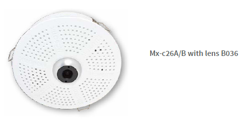
Variants/Accessories
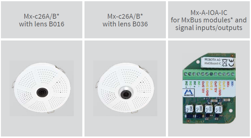
*Variant Mx-c26B supports MOBOTIX MxBus modules
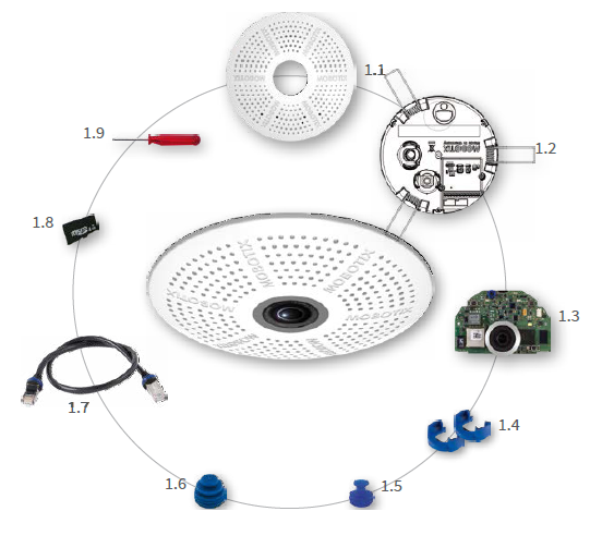
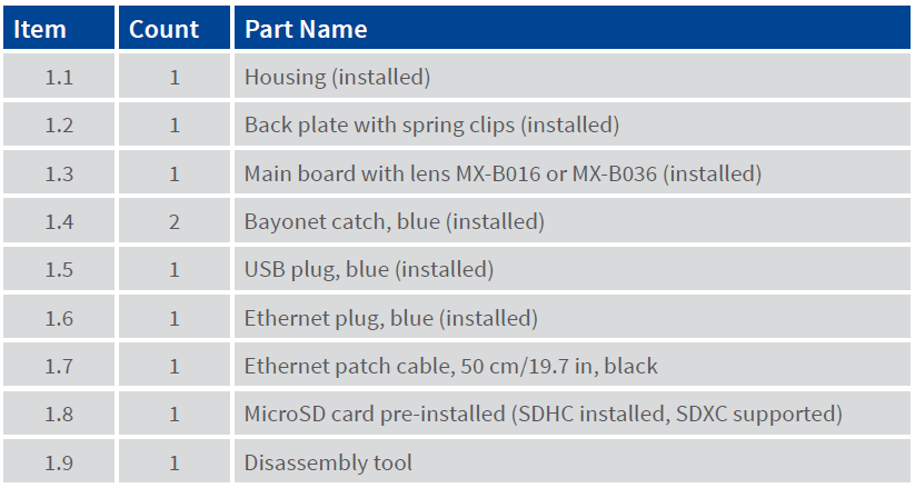
c26 Standard Delivery
Connection and Initial Operation of the c26
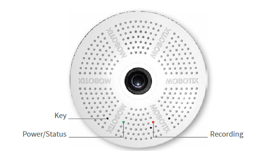
You can find detailed information on the installation and connections of the c26 in the Q25 Camera Manual (PDF, available on www.mobotix.com > Support > Download Center > Documentation > Manuals).Please note that the boot options of this camera have changed compared to its predecessor (see «Boot Options of the c26») and the camera only has one key. Regarding the rest of the initial operation of the c26, please see the Q25 Camera Manual in Chapter 3, «Initial Operation».
Use a suitable device for operating the camera key (e.g., an opened paper clip).
Inserting/Exchanging the SD Card
All camera models can use the integrated MicroSD card (SDXC) to record video data. In order to exchange the MicroSD card, please proceed as outlined in the following instruction. For information on reliable SD cards, please see the MOBOTIX website www.mobotix.com > Support > Download Center > Documentation > White Lists in the document MicroSD Card Whitelist for MOBOTIX Cameras. If the camera has not yet been installed, skip step 1.
Caution: In order to avoid damage from electrostatic discharge, you should touch a grounded device before opening the housing of the camera (e.g., the blank metal at the back of a computer). This will remove any static electricity that may have built up.
1. Remove camera, remove cables
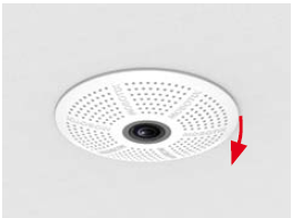
Pull the camera from its position by gently pulling the camera downward on one side, then the other side. Take care NOT to let the spring clips snap forward (risk of injury!). Remove all cables that are attached to the connectors on the back side.
2. Locate the locks
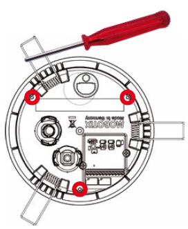
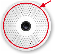
In order to remove the back plate, you will need to push the delivered disassembly tool (item 1.9) into the three holes on the back one after the other to release the locks (see red circles in figure).
3. Remove back plate
Insert the disassembly tool into a lock and press firmly until you feel a perceptible resistance 1

Gently push against the nearest spring clip to push the lock out of its seat and to lift the back plate from the housing 2 .
 Repeat the process for the two other locks and cautiously lift the back plate from the housing.
4. Remove/insert SD card
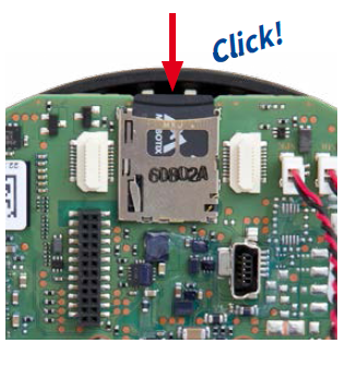
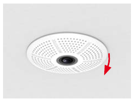
If a MicroSD card has been installed, gently press with your finger as indicated by the arrow until you hear a click. Then release the SD card. The card is protruding slightly and can be easily removed.Insert the new MicroSD card and gently press with your finger as indicated by the arrow until you hear the click.
5. Attach back plate
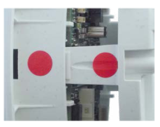
Make sure that the SD card is properly locked in place, since the card can be damaged otherwise.Begin by inserting the wide lock (next to the SD card) into the camera housing as shown. From the factory, the lock and the corresponding slot are highlighted by color mark.
 Make sure that the two other locks are also properly positioned, then press the back plate into its seat until you hear all three locks click into place.

6. Re-connect the cables
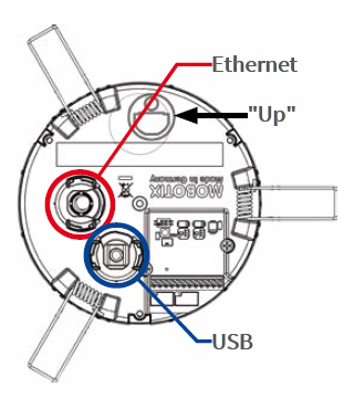
Insert the Ethernet cable and – if installed – the USB cable into the corresponding sockets and secure the connectors using the blue bayonet catches.
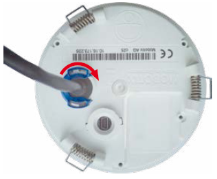 Press the spring clips back and insert the camera into its original mounting position (see «Installing the c26»).To finish, make sure that the camera image is properly aligned: If required, cautiously turn the camera to adjust image alignment.
Installing the Mx-A-IOA-IC
For the Mx-c26A/B, you can use the optionally available Mx-A-IOA-IC to attach external sensors using the signal inputs and to switch other devices via the signal outputs. When used with the the Mx-c26B, you can also attach MxBus devices (e.g., an MX-GPS-Box).

1. Insert the Mx-A-IOA-IC
On the back of the camera, remove the sticker that protects the receptacle and the camera’s interior from collecting dirt (see red arrow in figure to the right).
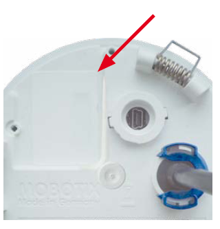
Carefully push the module board onto the receptacle. Secure the module board using the supplied Phillips screw (see red arrow in figure).

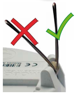
When attaching the connection wires to the Mx-A-IOA-IC, make sure the wires are guided to the module without tension (you could apply a cable tie and tie the wires to the network cable, for example).
2. Attach the connection cables
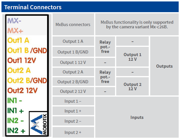
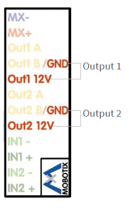
Attach the connection wires as shown in the terminal connector overview.
Installing the c26
Use the drilling template on the back for this purpose (red circle) or draw a circle with 105 mm/4.13 in diameter for the cut-out. Cut out the hole for the camera, then guide the Ethernet cable and any other cables you want to attach to the camera through the hole.
1. Connect the cables
Insert the cables into the appropriate connectors and fasten them using the blue bayonet catches.Make sure that the camera points into the desired direction: The icon on the back (black arrow) shows the “up” direction of the image.
2. Install the c26
Press the spring clips back and insert the c26 into the hole for the camera. The spring clips will snap outwards, thus firmly holding the camera in place.Make sure that you only press back the spring clips as shown in the image. Do not press them back any further as the springs may snap out of their fixtures otherwise.
Removing the c26
1. Pull out the camera
Pull the camera from its position by gently pulling the camera downward on one side, then the other side. Take care NOT to let the spring clips snap forward (risk of injury!).
2. Remove the cables
Remove the cables coming from the building (network cable, USB cable, MxBus and signal input/output wires). Pull out the camera.
Initial Operation of the c26
The initial operation starts with connecting the power supply (see section «Network and Power Connection, Additional Cables» in the Q25 Camera Manual). The first access follows the procedure described in the same manual in the section «Initial Operation of the Camera». All other tasks require access to the camera’s user interface in the browser. Enter the camera’s IP address into the address bar of the browser (user “admin”, password “meinsm”; password must be changed upon first login – camera software V5.1.x and higher).

1. Configuring and Using the Mx-A-IOA-IC
The camera will automatically detect an installed Mx-A-IOA-IC (see Camera Status, System section in browser).The signal inputs can be used right away in the signal input profiles in the Setup Menu > Event Overview. Likewise, the signal outputs can be used in the signal output profiles in Admin Menu > Hardware Configuration > Signal Out Profiles
In addition, the signal inputs/outputs have been entered automatically in the Admin Menu > Assign Wires dialog and can be used to control doors and lights.
To use one or both signal outputs not as potential-free outputs (for relays), but as 12 V outputs, open the Admin Menu > Hardware Configuration > Manage Hardware Expansions dialog. In the MxBus/IO Board section, click on Connect for each output you want to use.
2. Save the configuration
In the live image of the browser, select the Manage Settings quick control and set Store Entire Configuration as value. The camera stores the configuration in the permanent camera memory so that the settings will be applied at the next camera reboot.
Boot Options of the c26
By default, the camera starts as DHCP client and automatically tries to get an IP address from a DHCP server. To start the camera in a mode different from the default mode, you can activate the boot menu of the camera.
1. Prepare the Camera
- Disconnect the camera’s power supply.
- Make sure that you have suitable item such as a paper clip at hand, but never use sharp or pointed objects!
- Reconnect the power supply of the camera.
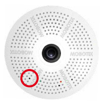
The red LED lights up 5 to 10 seconds after establishing the power supply and will stay on for 10 seconds.Briefly press the key by inserting the paper clip into the hole indicated by the red circle in the figure. The camera enters the boot menu, ready for selecting one of the boot options.
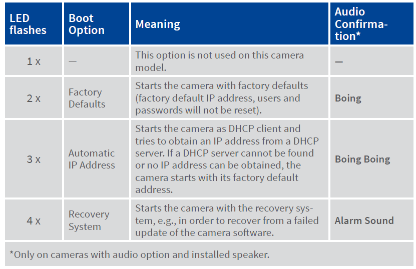
The LED now flashes once and repeats the flash signal after pausing for one second (the number of flashes indicates the current boot option). To go to the next boot option, briefly press the key again (< 1 sec). After the last boot option, the camera returns to the first option (LED flashes once).
3. Select a Boot Option
Press the paper clip longer (> 2 sec) into the hole. The camera confirms the selection by flashing rapidly three times. You can now remove the paper clip. After 20 sec, the camera will confirm the selection by playing a sound according to the table above.
If nothing is selected, the camera will resume its normal boot process after a certain time.
Important Notes
Safety Warnings
Notes on Installing: 
- This product must not be used in locations exposed to the dangers of explosion.
- Make sure that you install this product as outlined in the instructions of this Quick Install document. A faulty installation can damage the camera!
- When installing this product, make sure that you are only using genuine MOBOTIX parts and MOBOTIX connection cables.
- Only install this product on suitable, solid materials that provide for a sturdy installation of the fixing elements used.
Electrical installation:  Electrical systems and equipment may only be installed, modified and maintained by a qualified electrician or under the direction and supervision of a qualified electrician in accordance with the applicable electrical guidelines.Make sure to properly set up all electrical connections.
Electrical surges: MOBOTIX cameras are protected against the effects of small electrical surges by numerous measures. These measures, however, cannot prevent the camera from being damaged when stronger electrical surges occur. Special care should be taken when installing the camera outside of buildings to ensure proper protection against lightning, since this also protects the building and the whole network infrastructure.
Max. power consumption of attached extension modules: The power consumption of all attached MxBus modules must not exceed 2,5 W. When attaching modules to the MxBus connector and the USB socket, the power consumption of all attached modules must not exceed 3 W, if the camera is powered by PoE class 3.If PoE class 2 is used, the power consumption of all attached modules must not exceed 1 W!
Never touch the lens: Due to the high performance of the c26, the area of the image sensor can get quite hot, especially when the ambient temperature is also high. This does not affect the proper functioning of the camera in any way. For this reason, the product must not be installed within the reach of persons.
Power off before opening the camera: Make sure the power supply to the camera is disconnected before opening the camera housing (e.g., when exchanging the SD card or when opening the body to attach wires).
Network security:MOBOTIX products include all of the necessary configuration options for operation in Ethernet networks in compliance with data protection laws. The operator is responsible for the data protection concept across the entire system.The basic settings required to prevent misuse can be configured in the software and are password-protected. This prevents unauthorized parties from accessing these settings.
Legal Notes 

Legal aspects of video and sound recording: You must comply with all data protection regulations for video and sound monitoring when using MOBOTIX products. Depending on national laws and the installation location of the c26, the recording of video and sound data may be subject to special documentation or it may be prohibited. All users of MOBOTIX products are therefore required to familiarize themselves with all applicable regulations and to comply with these laws. MOBOTIX AG is not liable for any illegal use of its products.
Disposal

Electrical and electronic products contain many valuable materials. For this reason, we recommend that you dispose of MOBOTIX products at the end of their service life in accordance with all legal requirements and regulations (or deposit these products at a municipal collection center). MOBOTIX products must not be disposed of in household waste! If the product contains a battery, please dispose of the battery separately (the corresponding product manuals contain specific directions if the product contains a battery).
Disclaimer
MOBOTIX AG does not assume any responsibility for damages, which are the result of improper use or failure to comply to the manuals or the applicable rules and regulations. Our General Terms and Conditions apply. You can download the current version of the General Terms and Conditions from our website at www.mobotix.com by clicking on the COS link at the bottom of every page.
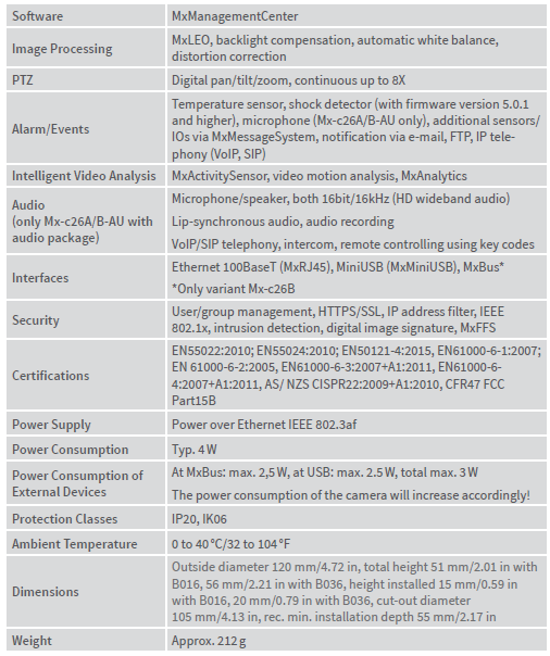
Technical Specifications c26

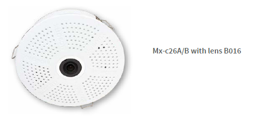
Forms of c26
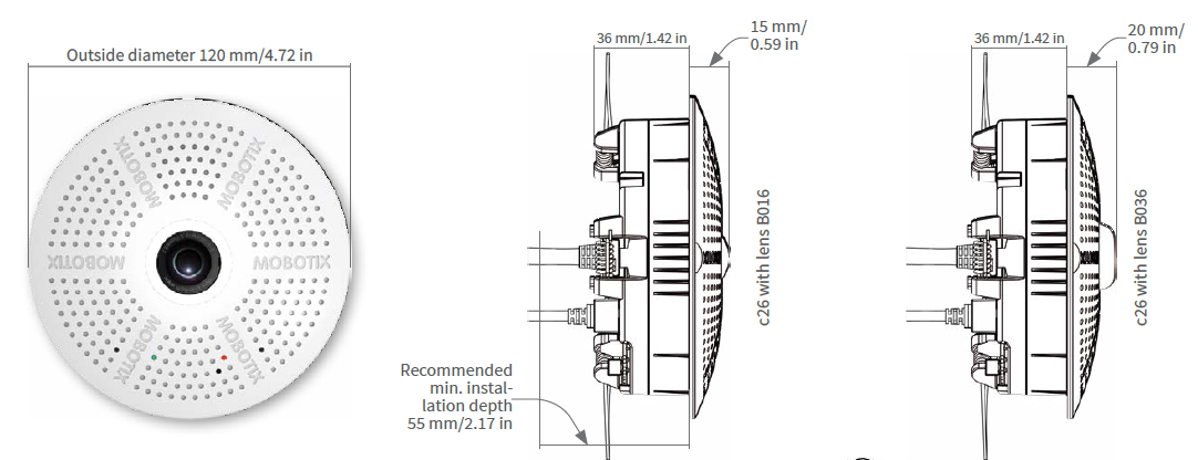
Dimensions/Drilling Template

Further information on www.mobotix.com:
- Products > Indoor Cameras > c26 Indoor 360°
- Support > Download Center > Documentation > Certificates & Declarations of ConformityMOBOTIX, the MX logo, MxPEG and MxActivitySensor are trademarks of MOBOTIX AG registered in the European Union, the U.S.A., and other countries
- Information subject to change without notice
- MOBOTIX does not assume any liability for technical or editorial errors or omissions contained herein
- All rights reserved
- © MOBOTIX AG 2017
References
[xyz-ips snippet=”download-snippet”]