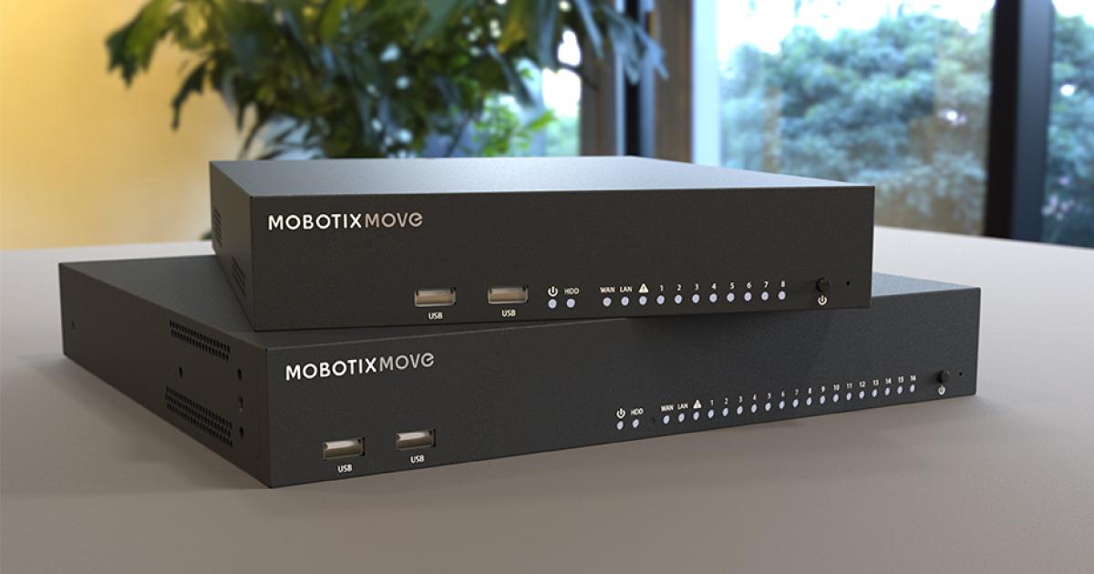
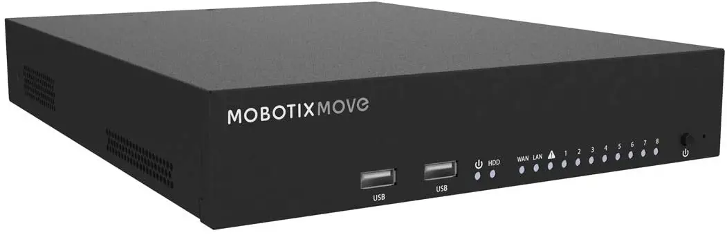
MOBOTIX MOVE NVR-8 Mx-S-NVR1A-8-POE
Support
If you need technical support, please contact your MOBOTIX dealer. If your dealer cannot help you, he will contact the support channel to get an answer for you as quickly as possible.If you have internet access, you can open the MOBOTIX help desk to find additional information and soft-ware updates. Please visit: www.mobotix.com>Support>Help Desk
Imprint
This document is part of the camera manufactured by MOBOTIX AG (called manufacturer in the following); the document describes how to use and to configure the camera and its components.Subject to change without notice.
Copyright InformationThis document is protected by copyright. Passing on information to others is not premitted without the prior written consent of the manufacturer. Violations will be subject to criminal punishment.
Patent and Copy ProtectionAll rights reserved. Trademarks or registered trademarks belong to the corresponding owners. Intel Inside and the Intel Inside logo are trademarks of Intel Corporation or its subsidiaries.
AddressMOBOTIX AGKaiserstrasse67722 LangmeilPhone: +49 6302 9816-103E-Mail: [email protected]Internet: www.mobotix.com
Safety Warnings
- This product must not be used in locations exposed to the dangers of explosion.
- Electrical systems and equipment may only be installed, modified and maintained by a qualified elec-trician or under the direction and supervision of a qualified electrician in accordance with the applic-able electrical guidelines. Make sure to properly set up all electrical connections.
- Make sure to install this product in a well-ventilated spot and do not close off any vent openings.
- Do not use this product in a dusty environment.
- Protect this product from moisture or water entering the housing.
- Make sure that you install this product as outlined in this document. A faulty installation can damage the product!
- Do not replace batteries of the product. Batteries can explode if they are replaced by an incorrect type.
- This equipment is not suitable for use in locations where children are likely to be present.
- This equipment is to be connected only to PoE networks without routing to other networks.
- If using a Class I adapter, the power cord shall be connected to a socket-outlet with proper ground con-nection.
- To comply with the requirements of EN 50130-4 regarding the power supply of alarm systems for 24/7 operation, it is highly recommended to use an uninterruptible power supply (UPS) for powering the product.
Legal Notes
Legal aspects of video and sound recording:You must comply with all data protection regulations for video and sound monitoring when using MOBOTIX AG products. Depending on national laws and the installation location of the MOVE NVR-8, the recording of video and sound data may be subject to special documentation or it may be prohibited. All users of MOBOTIX products are therefore required to familiarize themselves with all applicable regulations and to comply with these laws. MOBOTIX AG is not liable for any illegal use of its products.
Declaration of ConformityThe products of MOBOTIX AG are certified according to the applicable regulations of the EC and other coun-tries. You can find the declarations of conformity for the products of MOBOTIX AG on www.mobotix.com under Support > Download Center > Certificates & Declarations of Conformity.
RoHS DeclarationThe products of MOBOTIX AG are in full compliance with European Unions Restrictions of the Use of Certain Hazardous Substances in Electrical and Electronic Equipment (RoHS Directive 2011/65/EC) as far as they are subject to these regulations (for the RoHS Declaration of MOBOTIX, please see www.mobotix.com, Support > Download Center > Documentation > Brochures & Guides > Certificates).
DisposalElectrical and electronic products contain many valuable materials. For this reason, we recommend that you dispose of MOBOTIX products at the end of their service life in accordance with all legal requirements and regulations (or deposit these products at a municipal collection center). MOBOTIX products must not be disposed of in household waste! If the product contains a battery, please dispose of the battery separately (the corresponding product manuals contain specific directions if the product contains a battery).
DisclaimerMOBOTIX AG does not assume any responsibility for damages, which are the result of improper use or failure to comply to the manuals or the applicable rules and regulations. Our General Terms and Conditions apply. You can download the current version of the General Terms and Conditions from our website at www.mobotix.com by clicking on the COS link at the bottom of every page.
Installation
Package ContentsMake sure the delivered box contains the following items:
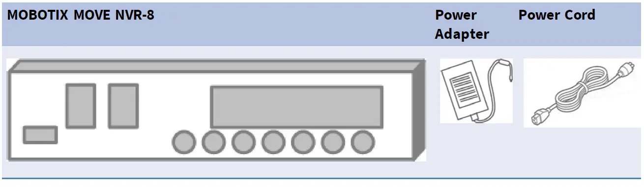
DocumentationScan the QR code or follow the link to find the MOBOTIX MOVE NVR-8 documentation:www.mobotix.com > Support > Download Center > Marketing & Documentation > Manuals > Accessories > MOVE NVR-8
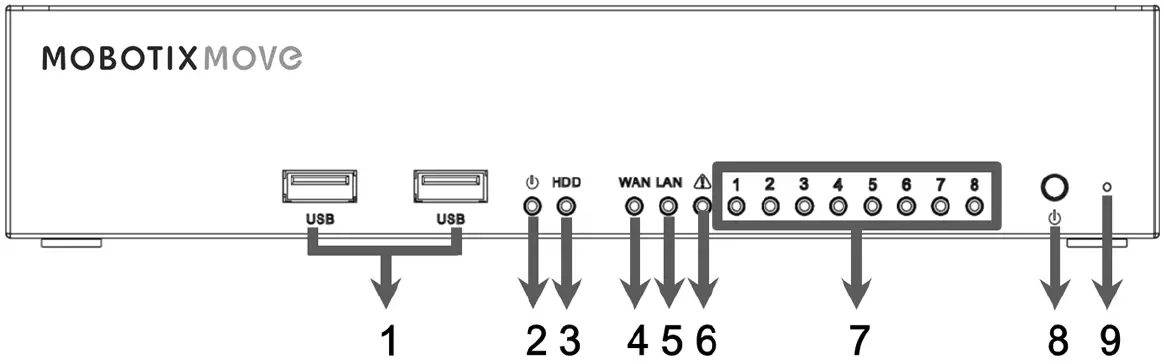
Front Panel
| Item | Name | Description |
| 1 | USB 2.0 Port x2 | The USB ports allow users to connect external USB devices, such as a USB mouse, a USB keyboard, a USB storage device, etc. |
| 2 | Power LED | This lights up when the power is on. |
| 3 | HDD LED | Flashing: The HDD is reading/writing data.
OFF: The HDD is not running. |
| 4 | WAN LED | Orange: Network speed is 1000Mbps.
Green: Network speed is 10/100Mbps. |
| 5 | LAN LED | |
| 6 | P. Max | This lights up as warning when there are 10 watts left to reach the power budget of PoE switch. |
| 7 | Camera LED | Lights up when the camera is powered up and has good network connection.
Lights up in Green when the power source is from NVR. Lights up in Orange when the camera is powered by external power supply. |
| 8 | Power But- ton | Press this button to power on the NVR system. |
| 9 | Reset Button | Press this button with a proper tool to restore the factory defaults of the NVR sys- tem. |
Rear Panel

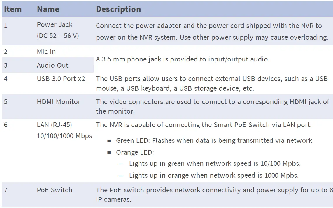
| 8 | WAN (RJ-45)
10/100/1000 Mbps |
This port is for connecting to the Internet (i.e., DSL router).
Green LED: Flashes when data is being transmitted via network. Orange LED: Lights up in green when network speed is 10/100 Mpbs. Lights up in orange when network speed is 1000 Mpbs |
| 9 | DisplayPort | The video connector is used to connect to a corresponding DisplayPort output jack of the monitor. |
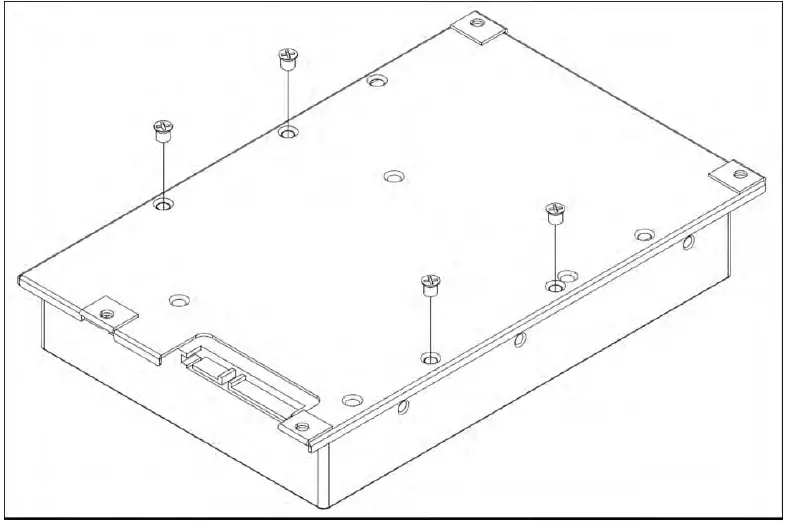
HDD Installation
Follow the steps below to install an HDD to the NVR:
- Open top cover.
- Remove HDD rack by unscrewing the four fixing screws.

- Fasten the HDD with the fixing screws delivered with the HDD as shown below.
- Mount the HDD rack back to its original position. No SATA cable required; the HDD is connected automatically.
- Close top cover.

List of Tested Hard Disks
Note: To ensure long-term reliable operation, make sure that you are using server-grade hard disks from the manufacturers’ series listed below.
| Brand | Series | Model Number | Firmware | Capacity |
| Seagate | Skyhawk | ST8000VX004 | AV01 | 8 TB |
| ST14000VX008 | 14 TB | |||
| Western Digital | Purple | WD82PURZ | 82.00A82 | 8 TB |
| WD140PURZ | 14 TB |
Configuration
Power On the NVR
- Before powering on the NVR, connect the necessary devices first:
- USB Mouse & USB Keyboard
- Internet (WAN)
- Monitor (HDMI and/or DisplayPort)
- IP Cameras via PoE ports
- Be sure to check the type of power source before plugging the power cord and power adaptor to the NVR.
- Lastly, press the Power Key on the front panel to power up the NVR system.Note: If you want to use temporary USB storage media, make sure those devices are connected only after the NVR has been powered on.
Login/Logout NVR SystemTwo accounts are predefined on the MOBOTIX MOVE NVR-8: “Guest” and “Admin”. The password for both users is “meinsm”.
LoginWarning: Always change the preset password of the “Guest” user to prevent unauthorized access to the unit.
Once the NVR is powered on, a popup window will appear:
- Click on OK to continue as user “Guest”.
- Click on Setup and change the default password “meinsm”. To show the virtual keyboard, click twice in the password field.
Note
- Password length is 6 to 12 characters.
- These characters are allowed: A-Z, a-z, 0-9, !#$%&’^_~
You are now logged in as Guest user. Proceed by changing the “Admin” user password as shown below:
- Move the mouse cursor to the top-right corner of the monitor, click Guest and select LogOut to open the login window.
- Select the administrator account “Admin”.
- Enter the password “meinsm”. To show the virtual keyboard, click twice in the password field.
- Press Enter on the keyboard or click Confirm in the login window to log into the NVR system as administrator.
Change the Admin User PasswordWarning: Always change the preset password of the “Admin” user to prevent unauthorized access to the unit.
- Log in as “Admin” user.
- Click on Setup > User Management > Edit.
- Click on Setup and change the default password “meinsm”. To show the virtual keyboard, click twice in the password field.
Note
- Password length is 6 to 12 characters.
- These characters are allowed: A-Z, a-z, 0-9, !#$%&’^_~
LogoutTo log out, click on the username and select LogOut.
Power Off the NVR
- Click Power icon at the top-right corner of the monitor, and the Power Panel will show up.
- Click Power Off icon , and the NVR system will start the shutdown procedure.
- Otherwise, click Cancel icon to abort.
Note: Do not remove the power source until the NVR is completely off.
Function Tabs
There are six function tabs including Live View, Playback / Export, Add Device, Record, Setup and Log.
- Live View: This function tab allows users to watch the live view of the connected IP devices and configure camera settings, such as PTZ control, image setup, video format, motion detection setup, etc.
- Playback / Export: Users can playback / export the recorded videos filtered by time / event and review / export the saved snapshots.
- Add Device: Users can search and add the IP devices to the NVR via network and through PoE ports.
- Record: The Record function tab allows users to arrange recording schedule, configure circular recording, and setup alarm behavior configuration.
- Setup: Under Setup function tab, users can setup the basic NVR settings, such as language, factory default, date / time setup, network setup, storage setup, user account management, etc.
- Log: The NVR divides the log data into four categories, User Operation Log, IP Camera Event, VA Detected Event and PoE Switch Event. Users can view, search and export the log data under this function tab.
Language and Date / Time Setup
Language Setup
1. Under Setup function tab, select Language to enter the language setting menu.2. Select the preferred language from the language drop-down list and click Apply to save the setting.3. Otherwise, click Cancel to cancel the setting.
Date / Time SetupThe Date / Time setting menu can be found under this path: Setup > System > Date / Time.
- To set a date, select the correct date from the calendar and click Apply to save the setting.
- To set up time, click on the target position in the time field (hour:minute:second AM/PM).
- Click buttons up or down or scroll the mouse wheel up / down to adjust the time values.
- Click Apply to save the setting.
Network Setup
Configure the network setup for the NVR to properly function with Ethernet connection. The Network setting menu can be found in this path: Setup > Network.
- Interface: Users can setup WAN and LAN configuration under this setting menu. Select ” eth0 (WAN)” to enter WAN configuration menu, and select “eth3 (LAN)” to setup the LAN settings.
- DHCP Setup: In the WAN configuration menu, the DHCP function allows users to obtain a dynamic IP address from DHCP (Dynamic Host Configuration Protocol) server when the NVR boots up.
- For DHCP users, check “Enable DHCP” box and click Restart. The IP address, Subnet Mask, Gateway and DNS settings listed in IPv4 will be retrieved from network servers. DHCP is dynamic that the settings change from time to time.
- For Non-DHCP users, uncheck “Enable DHCP” box, and fill out the required values listed in IPv4 by click-ing on the box next to each item and using the displayed number pad or the USB keyboard. Please obtain the information from the network service provider.
- Click Applyto save the setting.
Note: For more details regarding LAN configuration, refer to User’s Manual.
IP Camera Connection
Users can connect the IP cameras to the NVR via the network connection or through the PoE ports on the rear panel.Follow the instructions below to connect IP cameras to the NVR.
Add Device
- Enter Add Device function tab.
- Select the preferred device type, e.g. MOVE H.264, MOVE H.265, Onvif, etc., from the Device Filter drop-down list.
- Click Re-scan Device icon , and the NVR will start to search and list the connected devices meeting the searching criteria.
- Check “Device add to view” box in front of the desired IP device(s) to add it to the NVR.
Note: For more details regarding IP Camera connection and camera setup, refer to User’s Manual.
Check IP Camera Status
In the Live View function tab, the camera title bar is above each channel grid. The IP camera connection status can be examined by the color of the title bar.
| Title Bar Color | IP Camera Status |
| Grey | Not connected |
| Green | Connecting |
| Blue | In good connection |
| Red | Failed connection |
Playback / ExportThe NVR is capable of playing back the recorded videos by time / event and exporting the recorded videos and snapshots under Playback / Export function tab.Follow the instructions below to operate the functions.
Local Playback by Time
- Select any underlined date from the calendar, which indicates the recording data are available from these dates. The yellow stripe(s) in the time bar at the bottom of the function tab indicates available recorded videos for users to playback.
- Then, click and drag the time bar below to assign a preferred time from the time bar. Move the mouse cursor to the time bar and scroll up/down the mouse wheel to adjust the time scale to select the exact desired time. The selected time will be displayed above the time bar.
- Click Playback icon to start playing back the recorded videos.
Local Playback By Event
- In the Event Search Filter, check “Search By Time” box and specify the Start and End time of the desired time interval. Check “Search By Channel” box to select the desired channel. Check “Search By Type” box to select the preferred event type including Motion, Video Loss or Alarm.
- Click Search and the event videos, which meet the searching criteria will be listed next to the Event Search Filter.
- The Event List displays events by date/time, event type, and triggered camera channel in chronological order.
- Click on any event; the NVR will automatically start playing back the selected event video.
Video Export By TimeBefore starting the video export, make sure an external USB storage device is installed.
- Click and drag the Time Interval icon to the time bar to select the desired time interval of the recor-ded video.
- Adjust the preferred time segment by dragging the Time Range Adjustment icon .
- Click Start Export. An Export window will be displayed.
- Check the desired channel(s) and the exportation data including data size will be shown.
- Select the preferred video format.
- Click Confirm in the Export window to start the video export.
- Otherwise, click Cancel to abort.
Video Export By EventBefore starting the video export, make sure an external USB storage device is installed.
- Choose the preferred event video from the Event List.
- Click Start Export. An Export window will be displayed.
- The exportation data including data size will be shown.
- Select the preferred video format.
- Click Confirm in the Export window to start the video export.
- Otherwise, click Cancel to abort.
Snapshot
- Click Snapshot setting menu and select the preferred snapshot from the Snapshot List to check its pre-view.
- The information of the selected file, including the file created date/time, image resolution and image size, will be displayed next to the snapshot viewing window.
- Check the preferred file(s) to be deleted and then click Delete icon to remove the selected file(s) from the Snapshot List.
- Otherwise, click Select All icon to choose all the files at once.
Snapshot ExportBefore starting the snapshot export, make sure an external USB storage device is installed.
- Select the desired snapshot(s) from the Snapshot List.
- Click Export icon , and an Export window will be displayed.
- Click Confirm to start exporting the file(s); otherwise, click Cancel to abort.
Playback Control Icons
![]()
Video Export Function Icons
![]()
Snapshot Function Icons
![]()
Technical Specifications
| Type | Mx-S-NVR1A-8-POE |
| System | |
| Operating System | Embedded Linux |
| CPU | Intel Apollo Lake E3930 |
| RAM | LPDDR4, 2 x 1 GB |
| Boot Drive | eMMC Flash, 16 GB |
| Graphics | Intel HD Graphics 500 |
| DISPLAY PORT Output | 1920× (Full HD) |
| HDMI Output | 1920× (Full HD) |
| Audio Input | MIC-in, 3.5 mm x1 earphone |
| Audio Output | Line-out, 3.5 mm x1 earphone |
| USB Ports | USB 2.0 x2 (front); USB 3.0 x2 (rear) |
| Recording / Playback | |
| IPCAM Throughput | Average: 80 Mbps Peak: 120 Mbps |
| GPU Hardware Decoding | 12 CH real-time display, up to 360 decoding |
| Compression Format | H.264 / H.265 |
| Storage | |
| Build-in SATA Interface | 3.5” SATA3 x2 |
| Max. HDD storage support (internal & ext. iSCSI) | 20 TB |
| Onboard Hardware Interface | |
| M.2 (M-Key) | Yes |
| Network | |
| WAN Uplink | RJ-45 x1, 10/100/1000 Mbps |
| LAN Uplink | RJ-45 x1, 10/100/1000 Mbps |
| LAN ports with PoE | RJ-45 x8, 10/100Mbps |
| PoE Level | IEEE 802.3 af/at x8 |
| PoE & switch management | Linux SDK |
| Supported protocols | User Authentication, IEEE 802.1x, IPv4, TCP, UDP, DHCP, SMTP, RTP, RTSP, HTTP, NTP, DDNS, iSCSI |
| General | |
| Unit Dimensions (mm) | 220 x 275 x 44 |
| Unit Weight (kg) | 1.4 |
| Package Dimensions (mm) | 426 x 379 x 110 |
| Package Weight (kg) | 4.2 |
| Operating Temperature | 0 to 40 °C/32 to 104 °F |
| Operating Relative Humidity | 10 to 90 % non-condensing |
| System Power Supply | AC 100 to 240 V |
| PoE Budget per Port | 30 W |
| Total PoE Budget | 120 W |
Power Consumption of MOBOTIX MOVE Cameras
| Model | Order Code | Max. Power Consumption |
| BulletCamera 2MP | Mx-BC1A-2-IR… | 5.6 W |
| BulletCamera 4MP | Mx-BC1A-4-IR… | 13.68 W |
| SpeedDome | Mx-SD1A-330 | 25.4 W |
| SpeedDome IR | Mx-SD1A-340-IR | 44 W (external PoE injector required) |
| VandalDome 2MP | Mx-VD1A-2-IR… | 12.25 W |
| VandalDome 4MP | Mx-VD1A-4-IR… | 13.68 W |
List of Tested Hard Disks
Note: To ensure long-term reliable operation, make sure that you are using server-grade hard disks from the manufacturers’ series listed below.
| Brand | Series | Model Number | Firmware | Capacity |
| Seagate | Skyhawk | ST8000VX004 | AV01 | 8 TB |
| ST14000VX008 | 14 TB | |||
| Western Digital | Purple | WD82PURZ | 82.00A82 | 8 TB |
| WD140PURZ | 14 TB |
 report this ad
![]()
References
[xyz-ips snippet=”download-snippet”]