Moisture Meter
SAFETY NOTES
![]() CAUTIONObserve the instructions given in this manual. Failure to comply with instructions may damage the instrument and/or its components or be a source of danger for the operator.
CAUTIONObserve the instructions given in this manual. Failure to comply with instructions may damage the instrument and/or its components or be a source of danger for the operator.
NOTE is the warning that may bring the damage or failure to the instrument.CAUTION is the warning that may be a source of danger to the operator.
![]() CAUTION
CAUTION
- Read this manual before operate the instrument
- Comply to the instructions, otherwise. the functions may be inactive or weak.
- Do not use if the instrument is damaged or the case is fractured.
- Do not carry out any measurement in stormy or humid environments.
- Do not test high voltage cable circuit (e.g. 220V)
- Do not carry out any measurements in case gas, explosive materials or
- Flammables are present, or in dusty environments.
- Do not use instrument without battery cover or battery cover installed in a wrong way.
- Separate the testing wires from the tested wires before opening battery cover when replacing batteries.
- Do not attempt to repair the instrument. The instrument doesn’t include user replaceable parts.
- Electricity shock may happen when voltage exceed 30V AC or 60V DC.
BRIEF DISCRIPTION
This instrument is a multi-functional hand held cable testing tool. It has wideapplication with reinforced cable types and multiple functions. It is a necessary testing toot for telecommunication engineering, wiring engineering and network maintenance person.
Main Functions
- Wire tracing Trace RJ11, RJ45, cables or other metal wire (via adapter).
- Easy and fast to locate the breakpoint without opening the wire’s cover.
- Network cable collation: Judge short- circuit. breaking circuit, open circuit and crossing.
- Test line level, positive and negative polarity.
- Status of telephone line checking: Test the working status of telephone line (idle, ringing , and off-hook) and judge TIP and RING line.
- Check wire continuity.
General technical parameters
- TemperatureOperating temperature: 0 °C ~ 40 °C,. maximal 80% relative humidity (noncondensing)Storage temperature:-10~50°C, maximal 80% relative humidity (non condensing, battery not included)
- Altitude: <2000m( meter}
- Anti-explosion rating: IP 40
- Distance of emitting signal: 300m or so
- Safety class: IEC61010-1 600V CAT 111 , pollution class II.
- Battery Emitter: 6F22/9V; receiver: 61F22/9
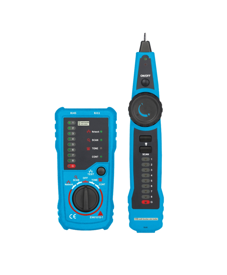
FRONT VIEW & INTERFACES

ACCESROIES
Clip adapter cable: One pieceRj1 1 adapter cable: One pieceRj45 adapter cable: One piece
Replace batteries as follows:
- Screw out the bolts of battery cover with screwdriver.
- Remove battery cover and old battery.
- Replace new battery with equivalent specification.
- Install battery cover and tighten the back cover with screwdriver.
Functions Operation
- Wire TracingThis function is capable of quickly finding the required line pairs among numerous ones. It is adaptable to network cable RJ 45 terminal, telephone line RJ11 terminal. Via an adaptor can test other metal wires.Operation methodA. Turn the emitter’s function rotary knob to SCAN position.B. Connect one end of tested line to the corresponding terminal of emitter (e.g. RJ45, RJ11 ) or connect to RJ11 terminal via an adaptor.C. SCAN indication light on means emitter starts to send signal to tested wire.D. Power on the receiver, hold receiver and press “SCAN’ button to test the other end of tested line (e.g. near line stacking of telephone line distribution cabinet, terminal box, hub, and exchanger). Compare the sound sent by receiver, the line with the loudest sound close to probe will be the target.E. Adjust the volume of receiver by pressing the volume rotary knob during test to adapt to site environment.Notes: You can connect headset to the headset jack of receiver in places with loud noise.During scanning, connect RJ11 terminal lo RJ 11 adapter, any clip of the adapter connect to the computer case or other ground-contacted metal objects.
- Network Cable CollationIt tests physical connection status of network cable, such as open circuit, short connection, miss wire and reverse connection.Operation methodA. Turn the emitter’s functions rotary knob to Network position.B. Connect one end of network cable to RJ45 socket of emitter, and connect another end of network cable to RJ45 socket of receiver.C. Press “TEST” button to start test. Line pair indicator lights will tell results.D. Short connection: there will be 2 or more lights on simultaneously on the receiver.The lighting quantity indications the quantity of shorted wires.E. Open circuit: On the receiver, the corresponding line pair indicator light will not turn on.
- Line Level, Positive and Negative Polarity TestUse emitter only to test line level, positive and negative polarity.Operation methodA. Turn the emitter’s function rotary knob to TONE position.B. Connect RJ1 1 crystal head terminal of adaptor to RJ 11 terminal of emitter. Clamp the tested line with a red-black clip.C. If telephone line status indicator light is red, the red end is Positive line, and the black end is Negative line. If it is green, the red end is Negative line and black end is Positive line.D. Level measurement. The more bright lights, the higher the level; the darker the lights, the lower the level.
- Status of Telephone Line TestUse the emitter only to test the status of working telephone lines.Operation method to judge TIP or RING lineA. Turn the emitter’s function rotary knob to TONE position.B. Connect RJ1 1 crystal head terminal of adaptor to RJ 11 terminal of emitter. Clamp the tested line with a red-black clip.C. If telephone line status indicator light is red, the red end is TIP line, and the black end is RING line. If it is green, the red end is RING line and black end is TIP line.D. Line level judging: The higher is the level, the higher is the level; The dimmer is the light, the lower is the level.Operation method to judge whether the telephone line is idle. ringing or off hookA. Turn the emitter’s function rotary knob to TONE position.B. Connect RJ 11 crystal head terminal of adaptor to RJ 11 terminal of emitter. Clamp the red clip to RING line and black clip to TIP line.C. If telephone line status indicator light is green, it means line is idle; Light off means off-hook; If it is green or red and flashes regularly, it means the telephone line is in ringing.
- Continuity CheckingIt can check continuity in circuits.A. Turn the emitter’s function rotary knob to CONT position.B. Connect RJ11 crystal head terminal of adaptor to RJ 11 terminal of emitter. Clamp the red and black clip to the two ends of the tested wire.C. CONT” light on means the wire is continuous. Less line impedance, the brighter is the light.
- Low Battery Capacity indicationEmitter low battery capacity indication: When battery of emitter is lower than working voltage, the power light will flash. It’s time to replace the battery.Receiver low battery capacity indication: There is a luminous diode on receiver probe, which becomes dim when voltage is low. When the indicator light is very dim, set the emitter to wire scanning and working status, approach RJ45 terminal of emitter with receiver probe, and adjust the volume of receiver till maximum. If there is no sound or very low sound sent by receiver, it’s time to replace the battery.
MAINTENANCE
Do not attempt to repair or service this instrument unless you are qualified to do so and have the relevant calibration, performance test and service instructions.Periodically wipe the case with a damp c loth and mild detergent. Do not useabrasives or chemical solvents.
Moisture Meter User Manual – Moisture Meter User Manual –
[xyz-ips snippet=”download-snippet”]