MONOPRICE Z-Wave Plus Smart In-Wall Dimmer Switch User Manual

SAFETY WARNINGS AND GUIDELINES
Please read this entire manual before using this device, paying extra attention to these safety warnings and guidelines. Please keep this manual in a safe place for future reference.
- This device is intended for indoor use only.
- Do not expose this device to water or moisture of any kind.
- Do not touch the device with wet hands.
- Prior to physical installation, use your circuit breaker or fuse box to remove electric power from the room, then test the circuit to ensure that electric power is not present.
- Prior to installation and before changing bulb(s) connected to this dimmer switch, slide the Air Gap Switch to the left. This physically removes power from the load. After the bulb(s) have been changed, slide the Air Gap Switch back to the right for normal operation.
- Clean using a soft, dry cloth only. Do not use chemical cleaners, solvents, or detergents. For stubborn deposits, moisten the cloth with warm water.
- This device has no user serviceable parts. Do not attempt to open, service, or modify this device.
INTRODUCTION
The Monoprice Z-Wave Plus® Dimmer Switch is a perfect replacement for a traditional dimmer switch, allowing for manual and remote control of incandescent, dimmable LED, and CFL lights. It is fully compatible with other Z-Wave® wireless devices, allowing for programmable functions in custom scenes. It can be used with most Z-Wave compliant controllers. The sliding Air Gap Switch completely disconnects power from the load, allowing for safe replacement of bulbs and preventing current leakage to the fixture(s). LED dimming performance may vary based upon dimmer type, model, manufacturer, circuit wiring, and circuit loading. There is no specific recommendation for product selection and no warranties of performance or compatibility are implied.
FEATURES
- Perfect replacement for a regular wall dimmer switch
- Compatible with 120 VAC, 15 amp electrical circuits
- Wireless Z-Wave® technology creates a mesh network for command and control interoperability with other Z-Wave compliant controllers and devices
- Preset brightness level options allow the dimmer to turn on to the last set brightness level
- The Air Gap Switch feature meets safety requirements to completely disconnect power from the load
PACKAGE CONTENTS
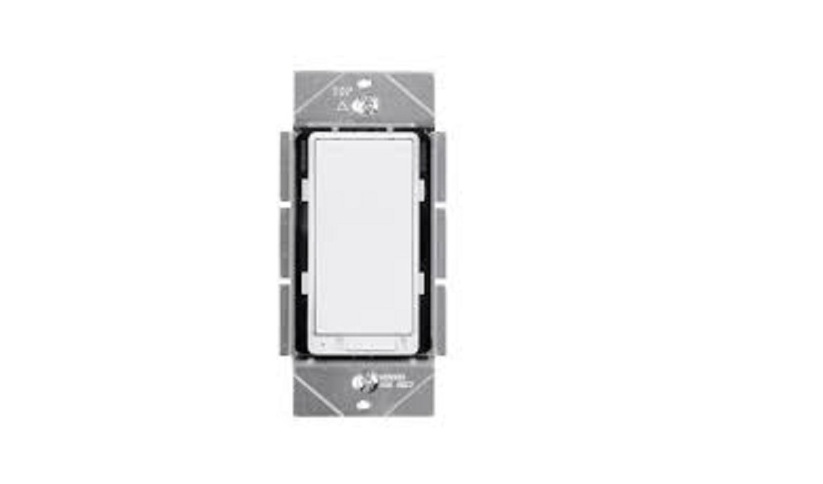
Please take an inventory of the package contents to ensure you have all the items listed below. If anything is missing or damaged, please contact Monoprice Customer Service for a replacement. 1x Z-Wave Plus® Smart In-Wall Dimmer Switch 1x Wall Plate with Mount and Screws 1x User’s ManualPRODUCT OVERVIEW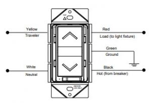
Important Note: Despite the presence of the Traveler line, this dimmer switch does not support the 3-way switch function. Do not use the traveler line.WIRING DIAGRAM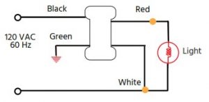
PHYSICAL INSTALLATIONWARNING!!! Prior to physical installation, use your circuit breaker or fuse box to remove electric power from the room, then test the circuit to ensure that electric power is not present.
- Remove the old switch and faceplate from the electric box, then disconnect the wire leads.
- Slide the Air Gap Switch on the dimmer switch to the left.
- Connect the wire leads to the switch, as shown in the WIRING DIAGRAM section above.
- Check each wiring connection to ensure that it is secure and that there are n o stray wire strands.
- Insert the switch into the electric box, then secure the switch to the box using two screws
- Use the included screws to attach the faceplate to the switch.
- Restore power at the circuit breaker or fuse box, then slide the Air Gap Switch to the right to complete the connection.
MULTIGANG INSTALLATION
When installing more than one dimmer switch in the same wall box, it may be necessary to remove the side tabs. Using a pair of pliers, bend each tab back and forth until it breaks off. Repeat for each tab to be removed. Note that removing tabs WILL REDUCE THE MAXIMUM LOAD CAPACITY.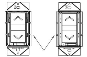
Tabs Removed for Mulitgang Installation When using only LED or CFL bulbs, refer to the following table for the load capacity of the dimmer switch with the tabs removed.
| LED/CFL Derating Chart | |||
| Load Capacity when Tabs are removed from: | |||
| Dimmable LED/CFL | 0 Side | 1 Side | 2 Sides |
| 150W | 150W | 150W |
When using a mixture of incandescent and LED/CFL bulbs, refer to the following table for the load capacity of the dimmer switch with the tabs removed.
| If the combined Wattage of ALL LED/CFL bulbs
on 1 dimmer is: |
Then the Maximum COMBINED Wattaged for the Incandescent/Halogen bulbs on EACH attached dimmer: | ||
| If NO Tabs are removed then Max Wattage is: | If 1 side of Tabs are removed then Max Wattage is: | If 2 sides of Tabs are removed then Max Wattage is: | |
| 0W | 600W | 500W | 400W |
| 1-25W | 500W | 400W | 300W |
| 26-50W | 400W | 300W | 200W |
| 51-75W | 300W | 200W | 100W |
| 76-100W | 200W | 100W | 50W |
| 101-125W | 100W | 50W | 0W |
| 126-150W | 0W | 0W | 0W |
CHANGING BULBS
Even with the dimmer switch turned off, a small amount of current still flows to the load. The Air Gap Switch on the dimmer switch physically disconnects power from the load. Perform the following steps whenever you change bulb(s) connected to the dimmer switch.
- Turn the dimmer switch off, then slide the Air Gap Switch to the left.
- Change the bulb(s).
- Slide the Air Gap Switch to the right.
OPERATION
The connected light/device can be turned on in two ways:
- Using a Z-Wave® controller or remote 2
- Manually using the paddle on the switch
Remote Operation Z-Wave remotes provide control of an individual device, groups of devices, and scenes. Some brands of Z-Wave certified remotes may not offer as much flexibility in how you can set up your lighting control network. Please refer to your controller’s instructions for details on its capabilities and instructions for adding and controlling devices.Manual Operation
- Momentarily press the top of the paddle to turn on the connected lights.
- Momentarily press the bottom of the paddle to turn off the connected lights.
- Press and hold the top of the paddle to increase the brightness of the connected lights. Release the paddle when the desired brightness level is achieved
- Press and hold the bottom of the paddle to decrease the brightness of the connected lights. Release the paddle when the desired brightness level is achieved.
Note: Pressing and holding the dimmer switch paddle until the light intensity is at the minimum setting does not turn the power OFF. To turn off the connected lights, momentarily the bottom of the dimmer switch paddle.With the Z-Wave® controller in “adding” mode, momentarily press the top or bottom of the paddle within 1.5 seconds. The controller will verify the addition and will assign a node ID to the switch.
- With the Z-Wave controller in “removing” mode, momentarily press the top or bottom of the paddle 3 times within 1.5 seconds. The controller will verify the addition and will assign a node ID to the switch.
- With the Z-Wave controller in “removing” mode, momentarily press the top or bottom of the paddle 3 times within 5 seconds. The controller will verify the removal, then will remove the dimmer switch from the network. When removed from the network, the LED will blink whenever the switch is turned on.
- If the primary controller is missing or inoperable, you can reset the dimmer switch to its factory default settings by first momentarily pressing the top or bottom of the paddle 3 times within 1.5 seconds, then pressing and holding the top of the paddle for 2 seconds.
Note: After a power failure, the dimmer switch will be turned off.
ADVANCED OPERATION
Configuration The following Advance d Operation parameters require that you have an advance d controller. Basic remotes do not have this capability.
| Parameter No. | Size | Descriptions | Valid Value | Default Value |
| 1 | 1 Byte | Synchronization of load power and LED indicator | 0: Power on, LED off
1:Power on, LED on |
Default = 0 |
Association
| Grouping ID | Max number of Nodes | Descriptions |
| 1 | 1 | Lifeline: Spend device reset locally notification |
| 2 | 5 | Status Report: Spend basic report |
ALL-ON AND ALL-OFF COMMANDSDepending upon your primary controller, the Monoprice Z-Wave® Switch can be set to respond to All-On and All-Off commands in one of four different ways. Some controllers may not be able to change the response from its default setting. Please refer to your controller’s instructions for information on whether or not it supports the configuration function and if so, how to change the setting.
- It will respond to All-On and All-Off commands (default).
- It will not respond to All-On or All-Off commands.
- It will respond to All-Off commands, but will not respond All-On commands.
- It will respond to All-On commands, but will not respond All-Off commands.
WIRELESS RANGE
This device complies with the Z-Wave® standard of open-air, lineof-sight transmission distances of up to 131 feet. Actual performance in a home depends on the number of walls between the remote controller and the destination device, the type of construction, and the number of Z-Wave enabled devices installed in the control network. AC powered Z-Wave enabled devices act as a signal repeater and multiple devices result in more possible transmission routes, which helps eliminate RF “dead spots.” The wireless RF range is affected in the following ways:
- Each wall or obstacle (i.e.: refrigerator, big screen TV, etc.) between the remote or Z-Wave device and the destination device will reduce the maximum range by approximately 25-30%.
- Brick, tile, or concrete walls block more of the RF signal than walls made of wooden studs and plasterboard (drywall).
- Wall mounted Z-Wave® devices installed in metal junction boxes may suffer a significant loss of range (approximately 20%) , since the metal box blocks a large r part of the RF signal. The following table shows some basic calculations for RF range.
| From the Remote (or repeating Z-Wave module) to
destination device: |
|||||
| Type of Construction | Wood Frame with Drywall | Brick, Tile or Concrete | |||
| Plastic
J-Boxes* |
Metal
J-Boxes |
Plastic
J-Boxes* |
Metal
J-Boxes |
||
| Number of Walls or Obstacles | 0** | 131’ | 100’ | 131’ | 100’ |
| 1 | 90’ | 70’ | 80’ | 60’ | |
| 2 | 60’ | 50’ | 50’ | 40’ | |
| 3 | 45’ | 40’ | 27’ | 20’ |
Note: The distances shown in the table above are typical examples. Actual performance in your home will vary.
SPECIFICATIONS
| Model | 36738 |
| Z-Wave® Frequency | 908.42 MHz |
| Voltage | 120 VAC, 60Hz |
| Incandescent | 600W |
| CFL/LED/Electronic Self- Ballasted | 2A (150W) |
| Operating Temperature | +32 ~ +104°F (0 ~ +40°C) |
| Wire Strip Length | 5/8″ (16mm) |
| Supply Connection | 14 AWG wires |
| Screw Torque | 20 lbf-in |
| Range | Up to 131 feet line of sight |
| Dimensions | 4.1″ x 2.0″ x 1.8″
(104 x 51 x 46 mm) |
| Weight | 4.6 oz. (130g) |
TECHNICAL SUPPORT
Monoprice is pleased to provide free, live, online technical support to assist you with any questions you may have about installation, setup, troubleshooting, or product recommendations. If you ever need assistance with your new product, please come online to talk to one of our friendly and knowledgeable Tech Support Associates. Technical support is available through the online chat button on our website www.monoprice.com or through email by sending a message to [email protected] Check the website for support times and links.
REGULATORY COMPLIANCE
Notice for FCC This device complies with Part 15 of the FCC rules. Operation is subject to the following two conditions: (1) this device may not cause harmful interference, and (2) this device must accept any interference received, including interference that may cause undesired operation. Modifying the equipment without Monoprice’s authorization may result in the equipment no longer complying with FCC requirements for Class B digital devices. In that event, your right to use the equipment may be limited by FCC regulations, and you may be required to correct any interference to radio or television communications at your own expense. This equipment has been tested and found to comply with the limits for a Class B digital device, pursuant to Part 15 of the FCC Rules. These limits are designed to provide reasonable protection against harmful interference in a residential installation. This equipment generates, uses and can radiate radio frequency energy and, if not installed and used in accordance with the instructions, may cause harmful interference to radio communications. However, there is no guarantee that interference will not occur in a particular installation. If this equipment does cause harmful interference to radio or television reception, which can be determined by turning the equipment off and on, the user is encouraged to try to correct the interference by one or more of the following measures:
- Reorient or relocate the receiving antenna.
- Increase the separation between the equipment and receiver.
- Connect the equipment into an outlet on a circuit different from that to which the receiver is connected.
- Consult the dealer or an experienced radio/TV technician for help.
RF Exposure Statement for FCCCaution This equipment complies with radiation exposure limits set forth for an uncontrolled environment. End users must follow the specific operating instructions for satisfying RF exposure compliance. This transmitter must be at least 20 cm from the user and must not be collocated or operated in conjunction with any other antenna or transmitter.Notice for Industry Canada This Class B digital apparatus complies with Canadian ICES-003. Cet appareil numérique de la classe B est conforme à la norme NMB-003 du Canada.RF Exposure Statement for Industry CanadaCaution This equipment complies with radiation exposure limits set forth for an uncontrolled environment. End users must follow the specific operating instructions for satisfying RF exposure compliance. This transmitter must be at least 20 cm from the user and must not be collocated or operated in conjunction with any other antenna or transmitter.Z-Wave® and Z-Wave Plus® are registered trademarks of Sigma Designs and its subsidiaries in the United States and other countries.
References
[xyz-ips snippet=”download-snippet”]