
Morningstar EMC-1 Ethernet-Meterbus Converter
Installation and Operation Manual

For the most recent manual revisions, see theversion at: www.morningstarcorp.com
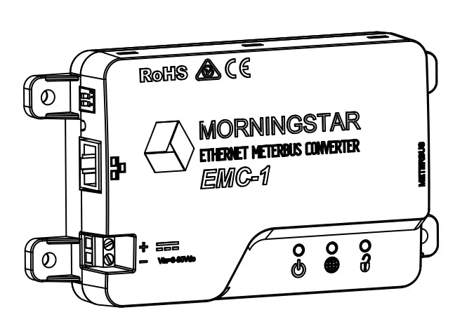


DIMENSIONS [inches (millimeters)]

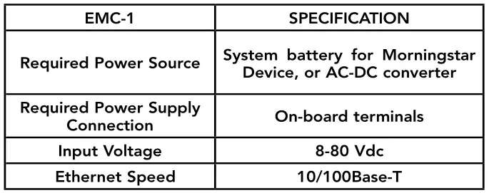
SPECIFICATION SUMMARY
1.0 GENERAL INFORMATION
1.1 Overview
The EMC-1 is a MODBUS TM Ethernet to Meterbus TM converter that bridges a TCP/IP connection to a Morningstar charge controller or inverter (Morningstar Device) not having built-in Ethernet connectivity. The connected device needs to have a Meterbus (RJ-11) port.
The EMC-1 acts as an Ethernet gateway that serves MODBUS IP and local Web pages. Ethernet networks also include local area networks (LANs) and Internet communications.
The EMC-1 supports the following communication capabilities with a Morningstar Device:
- Morningstar LiveView TM Internet Web monitoring and Network settings changes;
- Monitoring, logging and custom programming using Morningstar MSView TM PC software;
The table below lists products supported by the EMC-1, and includes port and data details. For a current list, see the latest manual version at:
* The EMC-1 included Y-cable is required to draw power from the RJ-11 port while communicating via the RS-232 port. See Section 2.3.2.
1.2 Features
The features of the EMC-1 are shown in Figure 1-1 below. An explanation of each feature follows.
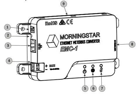
1 – DIP SwitchesDIP 1 enables Ethernet write commandsDIP 2 NOT USED
2 – Reset ButtonUsed for factory reset or firmware failure
3 – Ethernet port (RJ-45)Used to connect the EMC-1 to LAN / Internet
4 – Power Input8-80 Vdc power input
5 – Status LEDGreen and red lights indicate unit status
6 – Green/red LED – NOT USED
7 – Ethernet Write LEDGreen light indicates Ethernet write command capability
8 – Meterbus (RJ-11 port)Used to connect the EMC-1 to Morningstar Device
9 – DIN rail mounts (bottom of unit)35mm standard size
2.0 INSTALLATION
2.1 Mounting
The EMC-1 can be wall-mounted, surface-mounted or DIN rail mounted using basic tools:Flat head screw driverPhilips head screw driverDrill (if wall or surface mounting)1/8” drill bit (if wall or surface mounting)
Option 1 – Wall and Surface Mounting:
Step 1Locate the EMC-1 on a surface that is protected from direct sun, high temperatures, corrosive fumes, and water. Do not install in a confined area where battery gases can accumulate.
Step 2Before starting the installation, place the EMC-1 on the surface where it will be mounted and determine where the wires will enter and exit. Be sure there is sufficient bending room for the wires and communication cables. If possible, verify that the mounting screws will not penetrate wires or other objects located on the opposite side of the surface.
Step 3Place the EMC-1 on the intended mounting surface, mark four holes for drilling. Remove the EMC-1 from the surface, and using a 1/8” bit, drill pilot holes for each of the four mounting screws, as indicated on the surface.
Step 4Place the EMC-1 onto the surface and align the mounting feet holes with the four pilot holes. Use the included #10 screws to secure the EMC-1 to the surface.
Option 2 – DIN Rail Mounting:
The EMC-1 will also mount to standard 1-3/8” (35mm) DIN rail.
Step 1Choose the DIN rail mounting location. It should be protected from direct sun, high temperatures, corrosive fumes, and water. Do not install the EMC-1 in a confined area where battery gases can accumulate.
Step 2Confirm sufficient space above and below the DIN rail mounting location for EMC-1 cable connections . Using screws , secure the DIN rail to the desired surface.
Step 3The EMC-1 is designed for tool-less installation onto a DIN rail. There are four hooks on the bottom of the EMC-1 that slide over the upper and lower lips of the DIN rail.
2.2 Configuration
For communication via the EMC-1, the Morningstar Device’s DIP switches, if applicable, must be set forMODBUS communication. The SunSaver MPPT, ProStar MPPT, and the SureSine products need to have the appropriate DIP switch set for MODBUS communication. See Section 2.4 for EMC-1 DIP switchsettings.
2.3 Connections
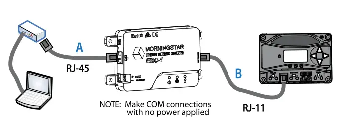
2.3.1 Installing the EMC-1
NOTE: Make COM connections with no power applied Insert an Ethernet cable (A) into the RJ-45 jack of the EMC-1. Insert the plug on one end of a six-conductor RJ-11 cable (B) into the RJ-11 jack on the EMC-1. Insert the plug on the other end of the RJ-11 cable into the RJ-11 port of the Morningstar Device. Seethe Operation section (3) for details on the start-up procedure.
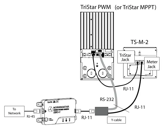
2.3.2 TriStar and TriStar MPPT Installation Using a Y-cable Adaptor
To communicate with the EMC-1, TriStar and TriStar MPPT controllers must be installed using the included Y-cable adapter. The RS-232 serial and RJ-11 plugs are connected at the controller, and the other RJ-11 plug at the EMC-1.
2.3.3 TriStar with Meter Application
Refer to Figure 2-2 below for EMC−TS-M-2 cable routing.
2.4 DIP Switch Set-Up
Figure 2-3 below shows DIP switch locations and functions:
2.4.1 Ethernet Writes
With DIP 1 ON, Ethernet writes are enabled, and custom programs, firmware updates (to the EMC-1) and network settings can be written to a Morningstar Device. Though this DIP switch is a safety feature designed to prevent unintended configuration changes to the Morningstar Device, DIP 1 is not a replacement for proper network security.
2.5 Connecting the Power Wires
The EMC-1 is powered from an 8-80 Vdc supply, such as an AC-DC converter or system battery connected to the power input provided on the EMC-1 unit. See the Operation section (3) for details on the start-up procedure. Connect the power wires as indicated in Figure 2-4 below.
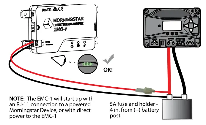
NOTE: Although the Morningsta r Device will provide power to the EMC-1 through the Meterbus port, it may not be sufficient under all operating conditions. The 8-80V power supply is required as a constant, reliable power source.
3.0 OPERATION
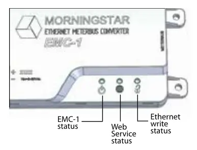
3.1 LED Indicators
There are three EMC-1 LED indicators – see Figure 3-1 below – that will show all statuses of the EMC-1. Left to right: Status LED (green / red); EnVision LED (green / red); Ethernet write enable LED (green).
3.2 Start-up
After the EMC-1 has been installed, as described in Section 2.3.1, the unit is started by connecting thepower supply, as described in section 2.5. On start-up, the status LED will flash green once, and then all LEDs [green, green, (green)] will light simultaneously for three seconds. Next, the EMC-1 will automatically begin searching for valid Morningstar Devices. If equipped, the Morningstar Device must have its MODBUS DIP switch enabled for the connection to be made.
EMC-1 START-UP SEQUENCE (with MS device connected)Status LED flash : GLEDs ON for 3 secs : G + G + (G)
With the EMC-1 powered, and the RJ-45 cable connected, RJ-45 LEDs will light as indicated in thetable below.
ETHERNET JACK INDICATIONSCondition | Green LED| Yellow LEDNetwork Connection OK | ON | OFFNetwork Activity | ON | BlinkingError | OFF | ON
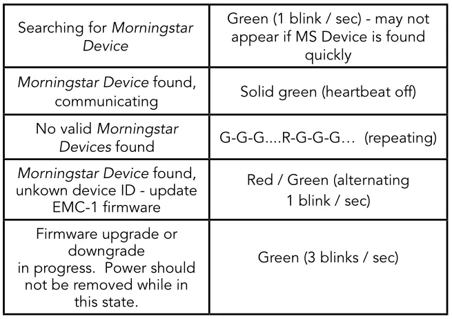
3.3 EMC-1 Status LEDs (green and red)
3.4 Ethernet Write LED (green)
DIP 1 OFF (green OFF) : Ethernet writes disabledDIP 1 ON (green ON) : Ethernet writes enabled
3.5 Connectivity
NOTE: For complete connection details, see the Morningstar Communications Document-Product Connectivity Manual, available on our website: www.support.morningstarcorp.com
3.5.1 MSView
MSView is a Morningstar software utility that allows real-time system data interface with a PC, thecapability to custom program charging parameters, and data logging. MSView is available for download, at no charge: www.morningstarcorp.com/msview/
The Device tab in MSView can be used to, “Search for Connected Devices”. The search screen will show the Morningstar Device, its 8-digit serial no. and the common IP address of the EMC-1 / Morningstar Device. The IP address can then be used to view Web pages as described in Section 3.6.2 below. The unit’s default IP address is 192.168.1.253
3.5.2 LiveView Web Pages
Using a Web browser, the EMC-1 allows access to a Morningstar Device’s LiveView Web pages via two methods:
- Enter the Morningstar Device’s IP address into the Address bar. If DHCP is not in use, the default static IP address is http://192.168.1.253
- Enter a Morningstar Device’s NetBIOS name [product abbreviation + 8-digit serial no.] into the Address bar e.g. http://ssmppt15320850
Product NetBIOS Abbreviations:TriStar MPPT : tsmpptProStar MPPT : psmpptProStar (Gen 3) : pspwmSunSaver MPPT : ssmpptTriStar PWM : tsSunSaver Duo : ssduoSureSine : suresine
NOTE: Many networks are DHCP-enabled, and the IP address assignment will change after some period of time. The NetBIOS address is a static Morningstar Device identifier, and will always point to the Morningstar Device.
After connection to the LiveView server, the following Web pages are available for viewing:
LiveViewThis is the default Web Page, which displays basic real-time system data, faults and alarms.
NetworkThis Web Page shows the Morningstar Device’s current Network settings, and allows the option of changing COM settings, and port forwarding:
DHCP : Primary DNSIP Address : Modbus IP Port 502Subnet Mask : Default Device (MODBUS) IDGateway : HTTP port 80
Data LogThis Web Page displays the current day, and a certain period of detailed historical system information, depending on the number of variables set for logging.
SystemThe System Web Page is used to update EMC-1 firmware. Connected device firmware cannot be updated through the System Web Page. The System Web page also shows specific EMC-1 diagnostic information.
3.5.3 Connecting to a LAN / WAN
After installing MSView on a PC on a local network, and with COM and power connections made, as described in Section 2.3, 2.4, a DHCP-enabled router will a utomatically assign an IP address and network settings to the EMC-1. The Morningstar Device will also be read for specific device information before connection is made. After the original assignment, network settings can be changed as desired using the LiveView Network Web Page.
ADVANCED TOPIC:
3.5.4 Connecting to the EMC-1 from a Remote Location (outside of the LAN) via the Internet / WAN
Basic Procedure:
- Verify that the Morningstar Device is correctly connected by accessing it via a Web browser (see Section 3.6.2). Navigate to the Network Page.
- In another browser window, enter the network router default gateway IP address (probably 192.168.1.1, but see Appendix I, Section II of Product Connectivity Manual – link below).
- Login to the network router, and choose a static IP address outside of the listed dynamic range.
- Return to the LiveView Network Page window, change the selection to, “Use Static IP Address”, enter the IP address chosen in the previous step, re-enter the remaining network settings listed in the box, including port 502, to direct incoming Internet requests to the Morningstar Device, and port 80 to view Morningstar Device Web pages on any Internet connected PC, then click the “Save” button.
- To maintain a recognizable public IP address, set up a Dynamic DNS service, or verify your router’s Dynamic DNS capabiltiy. The Morningstar Communications Document describes all aspects of connectivity and programming. See Appendix 1, Section 3 for full details.
3.6.1 Factory Reset
The EMC-1’s communication settings can be restored to the factory default conditions. The following values will be reset:
- TCP / IP settings
- Stored non-volatile product data
To Perform a Factory Reset:
- With the EMC-1 powered ON, press and hold the reset button until the status (left) LED starts to flash R-G, R-G….
- Release the reset-button.
- The EMC-1 will re-boot with the factory default settings.
3.6.2 To Recover from a Failed Firmware Update
- With the EMC-1 powered OFF, press and hold the reset button.
- Re-apply power, and the green status LED will start flashing three times every second. Release the reset button after the flashing begins.
- The recovery down-grade is in progress, and when complete, the EMC-1 will serve the System Web Page, and allow the user to attempt to re-load newer firmware.
3.7 Simple Network Management Protocol – v2c ( SNMP)
NOTE: A link to the Agent Management Information Base (*.MIB) file for a supported device, and OID (see description below) Tables with lists of relevant variables, can be downloaded, at no charge, from the SNMP FAQ on the EMC-1 Product Page. This page will also contain links to the current EMC-1 firmware file (on the Support Site) with release notes, and to an instructional video on how to perform firmware updates.
SNMP is often used by integrated systems to monitor individual pieces of equipment on the system network.
SNMP is supported by all compatible Morningstar devices through the use of the EMC-1 Ethernet adapter. SNMP functionality will be enabled through a remote firmware update of the EMC-1.
While the EMC-1 does not support asynchronous SNMP Traps, an SNMP browser running on the Network Management System (NMS)/Manager computer can provide effective alert notifications options. Using a polling frequency and conditional logic rule found in the NMS, the browser can be configured to alert the user of abnormalities.
An Object Identifier (OID) is a component of a MIB, containing a collection of variables e.g. solar specificvalues which can be queried by or configured from an SNMP application on a Network Management System (NMS)/Manager computer. For telecom and industrial applications that require SNMP monitoringof deployed systems, connected Morningstar devices will run/behave as SNMP Agents and will support the following commands:
NOTE: SNMP does not support the SET message, which allows a user to alter a setting on the device. This precaution helps to minimize the security and operational risks associated with unverified user access. Morningstar’s MSView PC software can be used to make changes to device settings, if desired.
GETA Manager-to-Agent request to retrieve the value of a variable or list of variables on a specific OID . Retrieval of the specified variable values is an atomic operation by the Agent i.e. it will not be completed without all requested values returned.
GETNEXTA Manager-to-Agent request to discover available variables and their values. Method used by SNMPmanager to work through an ordered list of OIDs according to the standard MIB hierarchy. Returns a response with variable binding for the next variable in the MIB.
GET BULKA sequence of GetNext requests, allowing a large segment of the MIB hierarchy to be queried by the SNMP manager from a managed device.
RESPONSEUsed by the SNMP agent to deliver requested information. Also acts as an acknowledgment.
DEFAULT PORT ASSIGNMENTPort 161 (EMC-1) SNMP Agent Receiving Port
3.7.1 SNMP Troubleshooting
Confirm data inconsistency with other MS monitoring platforms (MSView, LiveView, etc), and thenensure the following:
- The most up-to-date EMC firmware is being used. The MIB files are current and all reference MIBs are uploaded simultaneously (i.e MORNINGSTAR.mib, EMC-1.mib, and [DEVICE].mib)
- Scaling factors (contained in the MIB descriptions) for all relevant OIDs have been applied appropriately
- Each OID references the appropriate data value type listed in the MIB file
- The community string names are properly configured (will reset when the device is powered off). Write Community should be set to, “private”
- The network monitoring software is set to poll SNMP v2c
- The correct IP address and Root OID are used for SNMPWalk
4.0 TROUBLESHOOTING
4.1 Faults and Corrections
The following table 4.1 shows the main EMC-1 error conditions:

Problem:No valid Morningstar Devices found.
Solutions:Use an RJ-11 cable to connect Morningstar Device to EMC-1Turn on Morningstar Device MODBUS DIP switch.
Problem:Morningstar Device found, unknown device ID
Solution:Update EMC-1 firmware using System Web Page – see Section 3.6.2.
Problem:Internal fault condition
Solution:Contact Morningstar dealer for assistance
Problem:Cannot connect to the controller via Ethernet
Solutions:Turn on Morningstar Device MODBUS DIP switch. Confirm that the Morningstar Device is powered on. Verify good Ethernet cables and connections. Verify that NetBIOS name or IP address is correctly entered in the Web browser address bar – using http:// instead of https:// may help.
5.0 WARRANTY
LIMITED WARRANTY – Morningstar Solar Controllers and Inverters
All Morningstar Professional Series TM products, except the SureSine TM inverter, are warrantied to be free from defects in materials and workmanship for a period of FIVE (5) years from the date of shipment to the original end user. Warranty on replaced units, or field-replaced components, will be limited only to the duration of the original product coverage. Morningstar Essentials Series TM , and SureSine TM inverter, products are warrantied to be free from defects in materials and workmanship for a period of TWO (2) years from the date of shipment to the original end user. Warranty on replaced units, or field-replaced components, will be limited only to the duration of the original product coverage. Morningstar will, at its option, repair or replace any such defective units.
CLAIM PROCEDURE:
Before requesting warranty service, check the Operator’s Manual to verify product failure. Return the defective product to your authorized Morningstar distributor with shipping charges prepaid. Provide proof of date and place of purchase.
An RMA number must be issued by Morningstar prior to return of any unit(s) under this warranty. RMA information must include product model, serial number, detailed failure description, panel type, array size-configuration, type of batteries and system load details. This information is critical to rapid disposition of your warranty claim.
Morningstar will pay the return shipping charges if the repairs are covered under the warranty.
WARRANTY EXCLUSIONS AND LIMITATIONS
This warranty does not apply under the following conditions:
- Damage by accident, negligence, abuse or improper use
- PV or load currents exceeding the ratings of the product
- Unauthorized product modification or attempted repair
- Damage occurring during shipment
- Damage results from acts of nature such as lightning and weather extremes
THE WARRANTY AND REMEDIES SET FORTH ABOVE ARE EXCLUSIVE AND IN LIEU OF ALL OTHERS, EXPRESS OR IMPLIED. MORNINGSTAR SPECIFICALLY DISCLAIMS ANY AND ALL IMPLIED WARRANTIES, INCLUDING, WITHOUT LIMITATION, WARRANTIES OF MERCHANTABILITY AND FITNESS FOR A PARTICULAR PURPOSE. No Morningstar distributor, agent or employee is authorized to make any modification or extension to this warranty.
MORNINGSTAR IS NOT RESPONSIBLE FOR INCIDENTAL OR CONSEQUENTIAL DAMAGES OF ANY KIND, INCLUDING BUT NOT LIMITED TO LOST PROFITS, DOWNTIME, GOODWILL OR DAMAGE TO EQUIPMENT OR PROPERTY.
6.0 TECHNICAL SPECIFICATIONS
Electrical:DC input supply voltage range : 8-80 VdcSelf-consumption : ~2W
Data & Communications:Communications Ports : MeterBus (RJ-11), Ethernet (RJ-45)COM Protocols : Morningstar MeterBus; MODBUS TCP/IP; SNMPEthernet Speed : 10/100Base-T
Mechanical:IP Indoor, IP20Plastic enclosureDIN-rail mount : Standard 35mmWeight (unit only) : 0.28 lb / 0.13 kg
Environmental:Operating Temperature Range : -40ºC to +60ºCStorage Temperature : -55ºC to 80ºCHumidity : 100% non-condensing
7.0 CERTIFICATIONS

- C-Tick RCM compliant
- FCC Class B compliant
ENs Directives:
- Complies with ENs standards for CE marking
- Immunity: EN 61000-4-3: 2006; EN 61000- 4-6: 2009
- Emissions: CISPR 22: 2008
EMC-1 TM and Meterbus TM are trademarks of Morningstar Corporation
MODBUS TM and MODBUS TCP/IP TM are trademarks of Modbus IDA. www.modbus-ida.org
© 2020 Morningstar Corporation. All rights reserved.
MS-001796 v2.8
report this adMorningstar EMC-1 Ethernet-Meterbus Converter Installation and Operation Manual – Morningstar EMC-1 Ethernet-Meterbus Converter Installation and Operation Manual –
[xyz-ips snippet=”download-snippet”]