Morningstar RM-1 Digital Remote Meter
User Manual

1098 Washington Crossing RoadWashington Crossing, PA 18977 USAwww.morningstarcorp.com
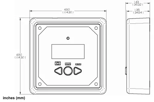
REMOTE METER DIMENSIONS
In Wall Mount
Frame Mount
Contents
1.0 Important Safety Instructions ………………………..42.0 General Information……………………………………….53.0 Installation………………………………………………………63.1 Frame Mount………………………………………………….63.2 In Wall Mount………………………………………………..84.0 Operation……………………………………………………….104.1 Meter Menus………………………………………………….104.2 Buttons ………………………………………………………….114.3 Icon Definitions………………………………………………114.4 Meter Options Menu……………………………………….124.5 Self Diagnostics (Self-Test) Menu…………………….134.6 Clear Counters, Min/Max Values……………………..135.0 Trouble shooting………………………………………………146.0 Limited Warranty………………………………………………157.0 Technical Specifications ……………………………………16
1.0 Important Safety Instructions
SAVE THESE INSTRUCTIONS:This manual contains important safety, installation and operating instructions for the Morningstar Remote Meter.
The following symbols are used throughout this manual to indicate potentially dangerous conditions or important safety instructions.
![]() WARNING: Indicates a potentially dangerous condition. Use extreme caution when performing this task.
WARNING: Indicates a potentially dangerous condition. Use extreme caution when performing this task.
![]() CAUTION: Indicates a critical procedure for safe and proper operation of the controller.
CAUTION: Indicates a critical procedure for safe and proper operation of the controller.
![]() NOTE: Indicates a procedure or function that is important for the safe and proper operation of the controller. General Safety Information
NOTE: Indicates a procedure or function that is important for the safe and proper operation of the controller. General Safety Information
- Read all instructions and cautions in the manual before starting the installation.
- There are no user serviceable parts inside the RM-1. Do not disassemble or attempt to repair the meter electronics.
- There are no fuses or disconnects in the RM-1.
- Do not allow water to enter the RM-1.
2.0 General Information
Thank you for selecting the Morningstar Remote Meter (RM-1) digital display. The RM-1 is an accessory for compatible Morningstar controllers and inverters.
The meter features a large 4-digit display and custom icons. The RM-1 provides comprehensive system information including voltage, current, and temperature. A Status LED indicates charging progress and controller operating state. Three (3) battery state-of-charge LEDs provide quick reference to the level of charge on the system battery. Soft buttons allow for easy navigation of the meter menus. The RM-1 also features self-diagnostics and error reporting for troubleshooting.
RM-1 software may be updated in the future to support new products. For questions concerningRM-1 compatibility with Morningstar controllers and inverters, please visit our website at:
http://www.morningstarcorp.com/
The software version can be found in the Self Diagnostics menu.
3.0 Installation
The RM-1 can be added to a compatible Morningstar controller or inverter when it is first installed, or at anytime after the controller or inverter has been in service. The meter can be mounted in two ways: Frame Mount or In Wall Mount. A plastic mounting frame is included for Frame Mount installations.
3.1 Frame Mount
Mount the RM-1 on a surface using the plastic mounting frame (included). No cut-outs inthe surface are required except for four (4) screw holes.
Tools and Materials Required:
- drill
- 3/32” drill bit (2.35 mm bit)
- mounting frame (included)
- (4) #8 x 1-3/4” screws (included)
- small hammer
- level
- safety glasses
![]() CAUTION: BEFORE installation connect the RM-1 to the Morningstar controller or inverter. Apply power and verify that the RM-1 is working properly. Resolve any issues before installing the meter and meter cable.
CAUTION: BEFORE installation connect the RM-1 to the Morningstar controller or inverter. Apply power and verify that the RM-1 is working properly. Resolve any issues before installing the meter and meter cable.
Step 1 Place the mounting frame against the wall or mounting surface in the desired location. Use a level to level the frame.
Step 2 Hold the leveled mounting frame in place on the wall with one hand. Place one of the #8 1-3/4” screws into a screw hole on the frame. Lightly tap the screw head with a hammer to mark the hole location. Repeat for the remaining three (3) screw holes.
![]() WARNING: BEFORE DRILLING, check the other side of the surface for electrical wiring, pipes or other obstacles that may interfere with the meter installation. Adjust meter location if necessary.
WARNING: BEFORE DRILLING, check the other side of the surface for electrical wiring, pipes or other obstacles that may interfere with the meter installation. Adjust meter location if necessary.
Step 3 Remove the frame. Using a drill and 3/32” (2.5 mm) drill bit, drill a 1” (25 mm) deep pilot hole at each of the four (4) marks from step 1. Don’t forget to wear safety glasses!
Step 4 Thread one end of the meter cable through the mounting frame and then plug it into the RM-1.
![]() NOTE: The RM-1 is provided with 10m (33 ft) of meter cable. If needed, the cable may be extended or replaced with regular phone cable. The phone cable must have at least 4 conductors, however 6-conductor cable is recommended.
NOTE: The RM-1 is provided with 10m (33 ft) of meter cable. If needed, the cable may be extended or replaced with regular phone cable. The phone cable must have at least 4 conductors, however 6-conductor cable is recommended.
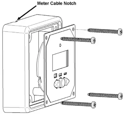
Step 5 The mounting frame is notched to allow the meter cable to exit the frame. Orient the notch in the preferred location. Seat the meter into the mounting frame. Align the four holes on the meter with the four screw holes on the frame. Align the frame holes with the four holes drilled into the mounting surface. Insert the four (4) #8 1-3/4” screws provided into each of the aligned holes but DO NOT TIGHTEN ALL THE WAY.
Step 6 Maneuver the meter cable so that it exits the frame through the notch in the frame. Hold the frame firmly against the mounting surface so that the cable cannot shift away from the notch. Fully tighten all four screws.
Step 7 Route the cable from the RM-1 to the controller or inverter. Secure the cable to the mounting surface with staples or wire clips. Do not staple through the wire! The cable should be protected from sharp edges, foot traffic, water/liquids, and extreme heat. Use grommets and wire loom as necessary. Do not run the meter cable directly parallel to power cables.
Step 8 Bundle and secure the excess cable where convenient.
Step 9 Plug the other end of the meter cable into the Controller or inverter. Verify that the meter powers up and begins displaying data. See the troubleshooting section for help if needed.
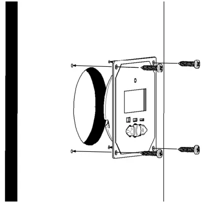
3.2 In Wall Mount
The In Wall mount method is a low-profile installation. The RM-1 faceplate sits flush with the mounting surface and the body of the meter rests in a hole cut-out in the mounting surface. The meter wiring is concealed behind the mounting surface or the interior of the wall.
Tools and Materials Required:
- drill
- philips screwdriver
- 3” hole saw (75 mm hole saw)
- level
- 3/32” Drill bit (2.35 mm bit)
- (4) #8 x ¾” screws (included)
- safety glasses
![]() CAUTION: BEFORE installation connect the RM-1 to the Morningstar controller or inverter. Apply power and verify that the RM-1 is working properly. Resolve any issues before installing the meter and meter cable.
CAUTION: BEFORE installation connect the RM-1 to the Morningstar controller or inverter. Apply power and verify that the RM-1 is working properly. Resolve any issues before installing the meter and meter cable.
Step 1 Locate the desired meter location on the mounting surface. Be sure there is sufficient room for the faceplate. Mark the center location of the meter with a pencil or pen.
![]() WARNING: BEFORE DRILLING, check the other side of the surface for electrical wiring, pipes or other obstacles that may interfere with the meter installation. Adjust meter location if necessary.
WARNING: BEFORE DRILLING, check the other side of the surface for electrical wiring, pipes or other obstacles that may interfere with the meter installation. Adjust meter location if necessary.
Step 2 Using a drill and 3” (75 mm or 76 mm) hole saw, cut a hole centered on the mark on the surface from step 1. Don’t forget to wear safety glasses!
Step 3 Insert the RM-1 body into the hole cut-out in the surface. Level the meter faceplate. Using a pencil or pen, mark the location of the four (4) mounting holes.
Step 4 Remove the meter from the cut-out. Using a drill and 3/32” drill bit, drill a 1” deep pilot hole at each of the four (4) marks.
Step 5 Connect one end of the RJ-11 meter cable into the RJ-11 connector on the controller or inverter. Route the cable from the controller or inverter to the RM-1.The cable should be protected from sharp edges, foot traffic, water/liquids, and extreme heat.Use grommets and wire loom as necessary.Do not run the meter cable directly parallel to power cables.If the back of the mounting surface is not accessible, fish tape or a coat hanger may be necessary to pull the meter cable up through the hole cut-out.
![]() NOTE: The RM-1 is provided with 30’ of meter cable. If needed, the cable can be extended or replaced with regular phone cable. The phone cable must have at least 4 conductors however 6-conductor cable is recommended.
NOTE: The RM-1 is provided with 30’ of meter cable. If needed, the cable can be extended or replaced with regular phone cable. The phone cable must have at least 4 conductors however 6-conductor cable is recommended.
Step 6 Plug the remaining end of the meter cable into the RM-1. Verify that the meter powers up and begins displaying information.
Step 7 Bundle and secure the excess cable. Push the excess cable back through the hole cutout. Insert the meter body back into the cut-out.
Step 8 Align the faceplate mounting holes with the pilot holes drilled in step 4. Using a Philips screwdriver, secure the meter to the surface using the four (4) #8 x ¾” screws provided.
4.0 Operation
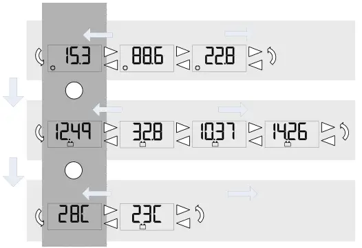
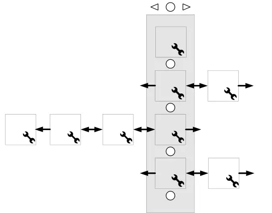
System information is arranged in rows as shown in the example meter menu in figure 3 below. Each row contains information related to a specific input or output (Solar, Battery, Load, etc). Use the “L” and “R” arrow buttons to view each screen in a row of information. After navigating to the last screen in a row, another advance in the same direction returns the user to the first screen of the row.
Each row of information is stacked vertically. Moving down to the next row requires one press of the “C” button. Pressing the “C” button on the last row returns the user to the top row.
Each row of information has a designated Main Screen. When advancing down to the next row of information, the Main Screen for the row will be the first screen displayed. This feature can be disabled in the Meter Options Menu. See section 4.4 for more information.
Meter Maps are included which detail the exact information displayed for each supported product.
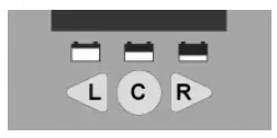
The RM-1 has three (3) buttons for meter menu navigation as shown in figure 4. Each press of the center “C” button advances down to the next row of information. Another push of the “C” button on the last row returns to the top row. Use the “L” and “R” arrow buttons to navigate to each display screen in a row of information.
4.3 Icon Definitions
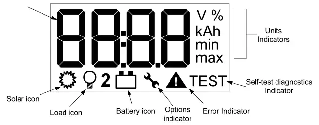
4-Digit Numerical Display – Displays numerical information such as voltage, current, and temperature values.
Units Indicators – Displays the units of the numerical information. Units may be used in combination if necessary ( e.g. V, max = maximum voltage )
Solar Icon – Indicates that displayed information relates to the solar input
Load Icon – Indicates that displayed information relates to the load output
Battery Icon – Indicates that displayed information relates to the battery.
![]() NOTE: if a controller has two solar, battery, or load connections, the “2” icon along with the appropriate icon indicates the second of the two connections.
NOTE: if a controller has two solar, battery, or load connections, the “2” icon along with the appropriate icon indicates the second of the two connections.
Options / Settings Indicator – The wrench options icon is displayed when the meter options menu is in use. See section 4.4 for more information.
Error Indicator – The error icon flashes when a controller error exists.
Self Diagnostics Indicator – Indicates that self diagnostics is in progress.
The Meter Options Menu is used to adjust temperature units, backlight timing, and the meter menu navigation. To access the Meter Options Menu, hold down all three (3) meter buttons for approximately five (5) seconds until “OPnS” and the wrench icon are displayed.
Use the “C” button to scroll through the parameters of the menu. Use the “L” and “R” arrow buttons to adjust the value of each parameter. An additional press of the “C” button after the last parameter automatically exits the Meter Options Menu.
Temperature Units: display temperatures in degrees C or degrees F.
Backlight Timer: During normal operation, a press of any meter button turns on the backlight. The backlight timer specifies how long the backlight shall remain on after the last button press.
- Off – backlight always offOn – backlight always on05 – backlight on for 5 seconds after last button push30 – backlight on for 30 seconds after last button push
Auto-return to Main Screens: If Auto-return is active, each press of the “C” button advances to the next row of information, starting with the main screen for that row of information. If Auto-return is turned off, each press of the “C” button advances to the next row and displays the last viewed screen for that row of information.
Diagnostic information can be displayed using the RM-1. To access the Self Diagnostics Menu, hold down the “C” button for 5 seconds. All LED segments and icons will illuminate on the LCD display. Release the “C” button to begin.
Diagnostic information will be displayed in sequential order as indicated on the back of the Meter Map for the product. Each press of the “C” button will advance to the next diagnostic screen. Refer to the product Meter Map for more information.
4.6 Clear Counters, Min/Max Values
Amp-hours and maximum/minimum values of current or voltage can be reset to zero with the RM-1. To reset these values, hold down buttons “L” and “R” for two (2) seconds. All values are reset to zero simultaneously and can be reset at any time, from any screen in the menu.
5.0 Trouble shooting
There is no display.
- Verify that the Morningstar controller or inverter connected to the RM-1 is powered and working properly. The meter is supplied power from the connected controller or inverter.
- Disconnect and reconnect the meter cable RJ-11 connection. Press firmly until there is a “click”.
- There may be a break in the meter cable. Inspect the cable for frays or pinches.
The LCD display is dim.
- Check the system battery voltage. Low battery voltage will cause the display to dim. The minimum operating voltage of the RM-1 is 8 Volts.
- In extremely cold temperatures the LCD may appear dim or it may react very slowly.
The meter is powered, however it does not display any data.
- The meter cable is damaged. Repair or replace the cable with a 4- or 6-conductor telephone cable with RJ-11 connectors.
- Software revisions may alter the menus or menu layout slightly. Check our website for the latest documentation.
Dust or debris has collected in the LCD window.
- Disconnect the meter cable and remove the 3 philips screws that secure the meter back cover.
- Remove the back cover and circuit board from the faceplate.
- Clean the label window with a damp cloth and reassemble. Do not use harsh solvents.
- Disconnect the meter cable and remove the 3 philips screws that secure the back cover.
- Remove the back cover and circuit board from the faceplate.
- Inspect the button contacts, clean dirt and debris with a damp cloth.
- Clean the gold button contacts on the PCB with alcohol and a cotton swap. Allow alcohol to try and reassemble.
6.0 Limited Warranty
The Remote Meter is warranted to be free from defects in material and workmanship for a period of FIVE (5) years from the date of shipment to the original end user. Morningstar will, at its option, repair or replace any such defective products.
CLAIM PROCEDURE
Before requesting warranty service, check the Operator’s Manual to be certain that there is a problem with the meter. Return the defective product to your authorized Morningstar distributor with shipping charges prepaid. Provide proof of date and place of purchase.
To obtain service under this warranty, the returned products must include the model, serial number and detailed reason for the failure. This information is critical to a rapid disposition of your warranty claim.
Morningstar will pay the return shipping charges if the repairs are covered by the warranty.
WARRANTY EXCLUSIONS AND LIMITATIONS
This warranty does not apply under the following conditions:
- Damage by accident, negligence, abuse or improper use.
- Unauthorized product modification or attempted repair
- Damage occurring during shipment
THE WARRANTY AND REMEDIES SET FORTH ABOVE ARE EXCLUSIVE AND IN LIEU OF ALL OTHERS, EXPRESS OR IMPLIED. MORNINGSTAR SPECIFICALLY DISCLAIMS ANY AND ALL IMPLIED WARRANTIES, INCLUDING, WITHOUT LIMITATION, WARRANTIES OF MERCHANTABILITY AND FITNESS FOR A PARTICULAR PURPOSE. No Morningstar distributor, agent or employee is authorized to make any modification or extension to this warranty.
MORNINGSTAR IS NOT RESPONSIBLE FOR INCIDENTAL OR CONSEQUENTIAL DAMAGES OF ANY KIND, INCLUDING BUT NOT LIMITED TO LOST PROFITS, DOWNTIME, GOODWILL OR DAMAGE TO EQUIPMENT OR PROPERTY.
1098 Washington Crossing Road,Washington Crossing, PA 19877 USAEmail: [email protected]Website: www.morningstarcorp.com
7.0 Technical Specifications
ELECTRICAL
- Self-consumptionBacklight off : 6 mABacklight on : 15 mA
- Minimum Operating Voltage : 8 V
MECHANICAL
- Connector type : RJ-11 (6 pin)
- Faceplate dimensions : 95.3 x 95.3 mm / 3.75 x 3.75 in
- Faceplate material : Powder coated steel
- Frame dimensions : 114.3 x 114.3 x 34.54 mm / 4.5 x 4.5 x 1.36 in
- Frame material : PBT Plastic
- Surface mount screws : #8 x 1” Philips head
- In Wall mount screws : #8 x 1-3/4” Philips head
- Meter cable : 10m (32.8 ft) – 6 conductor
- Meter cable temp. rating : 60 °C / 140 °F
- Meter weight : 135 g / 0.3 lbs
ENVIRONMENTAL
- Ambient Temperature : -20 °C to +60 °C / -4 °F to +140 °F
- Storage Temperature : -30 °C to +80 °C/ -22 °C to +176 °F
- Humidity : 100% N.C.
Specifications subject to change without notice.Designed in the U.S.A.Assembled in Taiwan

 report this ad
Morningstar RM-1 Digital Remote Meter User Manual – Morningstar RM-1 Digital Remote Meter User Manual –
[xyz-ips snippet=”download-snippet”]