 PROFESSIONAL DIGITAL TWO-WAY RADIOMOTOTRBO™XPR 7550 IS, XPR 7580eIS SERIES PORTABLE RADIOS


Your Quick Reference GuideThis Quick Reference Guide covers the basic operation of the radio. Check with your dealer or system administrator because your radio may have been customized for your specific needs.For more operational details and information on warnings and safety, refer to the following User Guide:Full Keypad Portable68009593001
Important Safety Information
RF Energy Exposure and Product Safety Guide for Portable TwoWay RadiosProduct Safety and RF Exposure Compliance![]()
![]()
Computer Software Copyrights
The Motorola Solutions products described in this manual may include copyrighted Motorola Solutions computer programs stored in semiconductor memories or other media. Laws in the United States and other countries preserve for Motorola Solutions certain exclusive rights for copyrighted computer programs including, but not limited to, the exclusive right to copy or reproduce in any form the copyrighted computer program.Accordingly, any copyrighted Motorola Solutions computer programs contained in the Motorola Solutions products described in this manual may not be copied, reproduced, modified, reverse-engineered, or distributed in any manner without the express written permission of Motorola Solutions. Furthermore, the purchase of Motorola Solutions products shall not be deemed to grant either directly or by implication, estoppel, or otherwise, any license under the copyrights, patents, or patent applications of Motorola Solutions, except for the normal nonexclusive license to use that arises by operation of law in the sale of a product.
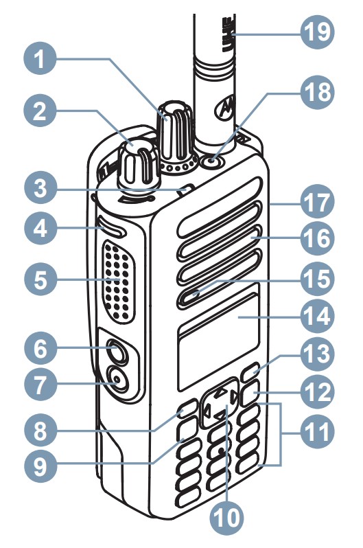
Radio Control


| 1. Channel Selector Knob2. On/Off/Volume Control Knob3. LED Indicator4. Programmable Side Button 15. Push-to-Talk (PTT) Button6. Programmable Side Button 27. Programmable Side Button 38. Programmable Front Button P19. Menu/OK Button10. 4-Way Navigation Button | 11. Keypad12. Back/Home Button13. Programmable Front Button P214. Display15. Microphone16. Speaker17. Universal Connector for Accessories18. Programmable Emergency Button19. Antenna |
Attaching the Battery


- Align the battery with the rails on the back of the radio.
- Slide the battery upwards until the latch snaps into place.
- Lock the battery latch.
Attaching the Antenna
- Turn off the radio.
- Set the antenna in the receptacle and turn clockwise.
Turning the Radio On and OffRotate the On/Off/Volume Control Knob clockwise or counterclockwise until a click sounds.Adjusting the VolumeRotate the On/Off/Volume Control Knob clockwise or counterclockwise.LED IndicatorsBlinking RedRadio has failed the self-test upon powering up, has moved out of range if Auto-Range Transponder System is configured, has Mute mode enabled, is receiving an emergency transmission, is transmitting in low battery state, or is indicating a battery mismatch.Solid GreenRadio is powering up, transmitting, or sending a Call Alert or an emergency transmission.Blinking Green Radio is receiving a call or data, detecting activity over the air, or retrieving Over-the-Air Programming transmissions.Double BlinkingGreen Radio is receiving a privacy-enabled call or data.Solid YellowRadio is monitoring a conventional channel.Blinking YellowRadio is scanning for activity, has yet to respond to a Call Alert, or all Capacity Plus-Multi-Site channels are busy.Double BlinkingYellow Radio has Auto Roaming enabled, has yet to respond to a Group Call Alert, is actively searching for a new site, is not connected to the repeater while in Capacity Plus, is locked, or all Capacity Plus channels are busy.
Display Icons
The following icons appear on the status bar at the top of the radio display. The icons are arranged left most in order of appearance or usage and are channel-specific.
| Emergency | Secure | ||
| Scan¹ | Unsecure | ||
| High Volume Data | Site Roaming | ||
| Mute Mode | Option Board | ||
| Tones Disabled | Power Level | ||
| Ring Only | Sign In | ||
| Notification | Sign Out |
- Not available for Capacity Max.
NOTES


References
[xyz-ips snippet=”download-snippet”]


