motrona Pulse Splitters for Incremental Encoders User Manual
Product features
- Power supply from 10 up to 30 VDC
- 1 encoder input for channels A, /A, B, /B, Z, /Z
- Input levels selectable between RS422, TTL and HTL
- Types with 4 or 8 outputs available (see below)
- Selectable output levels (RS422 / TTL / HTL)
- Auxiliary 5.5 VDC encoder supply output
- Easy cascading of further devices possible (incl. select function)
Available devices:
- 7186.5260: Pulse splitter with 8 outputs, short circuit proof encoder supply, potential separation between input and outputs and a temperature range of -20 to + 60 °C / -4° to 140 °F .
- 7186.5261: Pulse splitter with 4 outputs, short circuit proof encoder supply, potential separation between input and outputs and a temperature range of -20 to + 60 °C / -4 ° to 140 °F.
- 7186.5280: Pulse splitter with 8 outputs, short circuit proof encoder supply, complete potential separation (input, power supply, outputs) and a temperature range of -20 to + 60 °C / -4° to 140 °F.
- 7186.5281: Pulse splitter with 4 outputs, short circuit proof encoder supply, complete potential separation (input, power supply, outputs) and a temperature range of -20 to + 60 °C / -4°F to 140 °F.
|
Version: |
Description: |
| 7186.5280_01a/Jan09/af-hk | Original edition |
| 7186.5280_02a/Jan09/af-hk | Supplements for model 7186.5260 |
| 7186.5280_02b_oi/Sep-15/ag | “Safety Instructions”, “Technical Specifications” and design updated |
Legal notices:
All contents included in this manual are protected by the terms of use and copyrights of motrona GmbH. Any reproduction, modification, usage or publication in other electronic and printed media as well as in the internet requires prior written authorization by motrona GmbH.
Safety Instructions and Responsibility
General Safety Instructions
This operation manual is a significant component of the unit and includes important rules and hints about the installation, function and usage. Non-observance can result in damage and/or impairment of the functions to the unit or the machine or even in injury to persons using the equipment!
Please read the following instructions carefully before operating the device and observe all safety and warning instructions! Keep the manual for later use.
A pertinent qualification of the respective staff is a fundamental requirement in order to use these manual. The unit must be installed, connected and put into operation by a qualified electrician.
Liability exclusion: The manufacturer is not liable for personal injury and/or damage to property and for consequential damage, due to incorrect handling, installation and operation. Further claims, due to errors in the operation manual as well as misinterpretations are excluded from liability.
In addition the manufacturer reserve the right to modify the hardware, software or operation manual at any time and without prior notice. Therefore, there might be minor differences between the unit and the descriptions in operation manual.
The raiser respectively positioner is exclusively responsible for the safety of the system and equipment where the unit will be integrated.
During installation or maintenance all general and also all country- and application-specific safety rules and standards must be observed.
If the device is used in processes, where a failure or faulty operation could damage the system or injure persons, appropriate precautions to avoid such consequences must be taken.
Use according to the intended purpose
The unit is intended exclusively for use in industrial machines, constructions and systems. Nonconforming usage does not correspond to the provisions and lies within the sole responsibility of the user. The manufacturer is not liable for damages which has arisen through unsuitable and improper use.
Please note that device may only be installed in proper form and used in a technically perfect condition – in accordance to the Technical Specifications (see chapter 2). The device is not suitable for operation in explosion-proof areas or areas which are excluded by the EN 61010-1 standard.
Installation
The device is only allowed to be installed and operated within the permissible temperature range. Please ensure an adequate ventilation and avoid all direct contact between the device and hot or aggressive gases and liquids.
Before installation or maintenance, the unit must be disconnected from all voltage-sources.Further it must be ensured that no danger can arise by touching the disconnected voltagesources.
Devices which are supplied by AC-voltages, must be connected exclusively by switches, respectively circuit-breakers with the low voltage network. The switch or circuit-breaker must be placed as near as possible to the device and further indicated as separator.
Incoming as well as outgoing wires and wires for extra low voltages (ELV) must be separated from dangerous electrical cables (SELV circuits) by using a double resp. increased isolation.
All selected wires and isolations must be conform to the provided voltage- and temperatureranges. Further all country- and application-specific standards, which are relevant for structure, form and quality of the wires, must be ensured. Indications about the permissible wire crosssections for wiring are described in the Technical Specifications.
Before first start-up it must be ensured that all connections and wires are firmly seated and secured in the screw terminals. All (inclusively unused) terminals must be fastened by turning the relevant screws clockwise up to the stop.
Overvoltages at the connections must be limited to values in accordance to the overvoltage category II.
For placement, wiring, environmental conditions as well as shielding and earthing/grounding of the supply lines the general standards of industrial automation industry and the specific shielding instructions of the manufacturer are valid. Please find all respective hints and rules on www.motrona.com/download.html –> “[General EMC Rules for Wiring, Screening and Earthing]”.
Cleaning, Maintenance and Service Notes
To clean the front of the unit please use only a slightly damp (not wet!), soft cloth. For the rear no cleaning is necessary. For an unscheduled, individual cleaning of the rear the maintenance staff or assembler is self-responsible.
During normal operation no maintenance is necessary. In case of unexpected problems, failures or malfunctions the device must be shipped for back to the manufacturer for checking, adjustment and reparation (if necessary). Unauthorized opening and repairing can have negative effects or failures to the protection-measures of the unit.
Introduction and Block Diagram
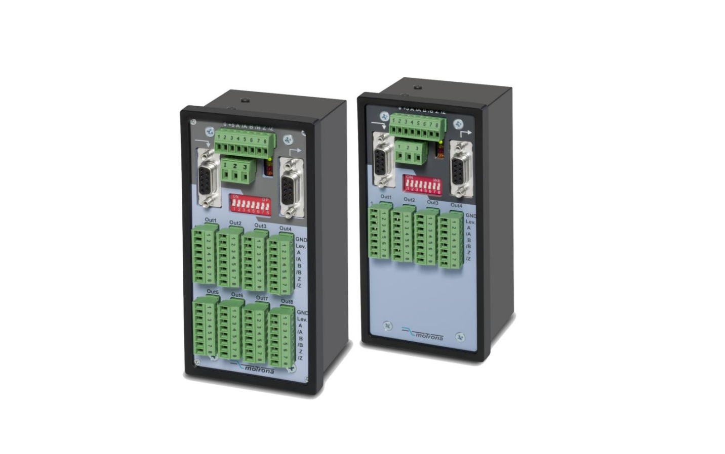
7186.5260, 7186.5261, 7186.5280 and 7186.5281 represent a series of incremental encoder splitters with a most compact, space-saving design and with most versatile technical features.All models are fully identical except for the number of output channels (4 or 8 channels) and the system of potential separation.
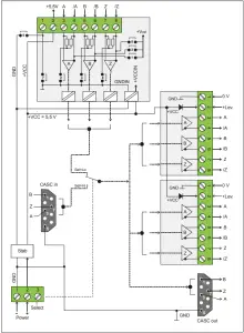
Models 7186.5260 and 7186.5261 are lower in price but provide only a 2-circuit potential separation between the input on one side and the outputs with power supply on the other side.
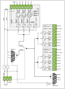
Models 7186.5280 and 7186.5281 provide total galvanic separation between inputs, the power supply and all outputs one against each other. This feature, in general, can be most advantageous with impulse distribution among expanded production lines with adverse conditions ofEMC / grounding / potential shift etc.
The encoder input is switch-selectable for operation with either standard RS422 signals, with differential TTL or HTL signals or with single-ended HTL encoder signals. All encoder outputs provide fully isolated push-pull drivers with individual assignment of the output level for each of the output channels.
Separate cascading ports provide easy cascading of multiple units without loss of regular encoder outputs. Furthermore, cascaded units allow selection and commutation between different encoder inputs.
The adjoining block diagrams clearly explain the principle of operation and the potential conditions between all circuits. For simplification the illustrations show only two of the outputs, since all other outputs are fully identical.
All units of this series provide an extended range of ambient temperatures for use under difficult environmental conditions (“Technical Specifications”).
Block diagram 7186.5260 and 7186.5261
Block diagram 7186.5280 and 7176.5281
Electrical Connections and LED Function
Power Supply and LEDs
The unit provides a 3-position screw terminal strip for supply from a 10 – 30 VDC power unit.The current consumption is approx. 40 mA (no-load operation). The “Select” input terminal provides selection of the desired source encoder. Details will be described later.
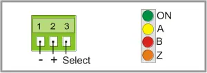
The upper LED (green) signals that power is applied to the unit.
The lower LEDs (yellow, red, orange) signal the actual logical states of the input channels A, B and Z. With very low input frequencies it is possible to visually check the input pulses, the phase displacement A/B and the index pulse function of an encoder.
Auxiliary Encoder Supply
The input encoder must be connected to the 8-position input terminal strip.Depending on the application and the encoder type, one of the following options will apply for the power supply of the encoder:
- Remote supply via separate source
- Same power source that also supplies the 7186.5280 unit (10 – 30 VDC)
- Use of the built-in auxiliary 5.5 volts power supply (terminal 2 of the input connector)
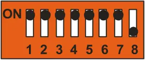
 When the built-in 5.5 volts power should be used to supply the encoder, position 8 of the DIL switch has to be set to “ON”.
- This action will suspend the galvanic separation between input and the unit power supply.
- With models 7186.5280 and 7186.5281, also in this case full isolation to all outputs will be maintained.
Impulse Inputs
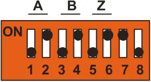
The 8-position DIL switch on the front side provides setting of the desired signal formats and levels. These settings are separately for each of the channels A / B / Z (see block diagram).For simplification, a short form of the four most common applications is shown below, with the encoder supply omitted:
Encoders with differential output(valid for output levels TTL/ 5 volts and for HTL / 10 – 30 VDC as well)
|
Terminal Connections |
DIL Switch Setting |
|
 |
Encoders with single-ended output, without inverted signals(acceptable only with HTL level 10 – 30 VDC)
|
Terminal Connections |
DIL Switch Setting |
|
 |
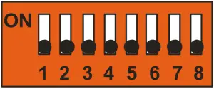
Differential signals from an encoder simulation(TTL level with remarkable noise)
Basically, signals generated by the encoder simulation of a drive can be treated similarly to a TTL encoder as described in section 3.3.1 (see above). If however there should come up problems with the quality of the output signals (caused by awkward environmental conditions), the following mode of connection may remarkably improve the situation. This is a pure differential operation with fully floating potential, without any reference point.It is important to leave terminal 1 unconnected.
|
Terminal Connections |
DIL Switch Setting |
|
 |
Differential signals for encoder channels A and B,but single-ended marker pulse from proximity switch or photocell
Besides the most common standard configurations shown before, the unit allows setting of any other input configuration (e.g. differential encoder inputs on channels A, /A, B, /B, but singleended index signal on input Z (from a proximity switch, photocell or similar)
The block diagram shows which of the DIL switch positions is responsible for each of the channels. It is easy to figure out other settings from the examples given in this manual.
|
Terminal Connections |
DIL Switch Setting |
|
|
- The normal encoder input terminal will not accept any single-ended signals with TTL level, i.e. single-ended signals have to provide HTL level
- Nevertheless, in special cases, the cascading inputs of the unit can be used to apply single-ended TTL signals (CMOS, Low <0.8 V, High >3.5 V). This however assumes proper EMC conditions and environment as well as short cables on the input side.
- The input terminal strip provides a codification to avoid accidental mix-up with the other connectors of the unit
The Outputs
All outputs provide the non-inverted and the inverted signals at any time, even when on the input side the inverted signals are not available.
The potential situation between the outputs and other circuits is clearly explained by the block diagrams in chapter 1. On terminal 1 (0V) and terminal 2 (+Lev.) a remote voltage has to be applied to each output stage, which at the same time also determines the signal level on the corresponding output*). The permitted range is from 5 to 30 volts and the signal swing will be about 0.7 volts less than the remote voltage applied. All output lines are permanently shortcircuit-proof and the maximum output current is 30 mA per line.
The terminal assignment can be found in the block diagram and is also printed to the front plate of the unit. All output terminal strips have the same codification, since it is fully unimportant to which of the outputs a terminal strip is connected (only the external voltage applied to the “Lev.” input of the mating connector is responsible for the output level).
With models 7186.5260 and 7186.5261, terminals 2 (+Lev.) of all outputs are already connected to the internal +5 V power supply by diodes. This means, where 5 volts TTL signals are needed, it is not really necessary to apply any remote voltage to the (+Lev.) terminal.With models 7186.5280 and 7186.5281 these diodes are missing, therefore a remote voltage must be applied at any time to make the outputs work.
Cascading of Several Units and Encoder Select Function
The unit can be cascaded very easily to any number of output channels, without loss of regular encoder outputs. For cascading, pins 1, 3, 5 and 7 of the cascading output of the first unit must be connected to the corresponding pins of the cascading input of the follower unit.
An appropriate ribbon cable connection is available under motrona part # FK470

Cascading lines use the same common GND potential as the power supply of the unit. This however does not mean any disadvantage in terms of galvanic isolation etc. since cascading units are always mounted alongside and are also supplied from the same power source.
Cascaded units allow selection of the active source encoder via the encoder select input on the 3-position power connector (see also block diagram):
- LOW (or open): outputs refer to the encoder input of the same unit
- HIGH (10 – 30 VDC): outputs refer to the encoder input of the preceding unit
It is possible at any time to switch over from one to the other source encoder during operation.
Where only one common encoder is used, the select input of the first unit remains unconnected. The select inputs of all follower units are advantageously connected to the +pole of the power supply located next to the select input.
Technical Specifications
| Power supply |
|
|
| Encoder supply |
|
|
| Incremental input |
|
|
| Select input |
|
|
| Cascading in / out |
|
|
| Incremental outputs |
|
|
| Potential separation | in / out: | potential separation between input and the outputs |
| Indicators |
|
4 LEDs
1 x green for “ready to operate” state and each 1 x yellow, red and orange for logical conditions of inputs A, B, Z |
| Housing |
|
|
| Ambient temperature |
|
|
| Failure rate | MTBF in years | 7186.5260: 79.1 a / 7186.5261: 102.9 a / 7186.5280: 64.2 a / 7186.5281 a (long-term usage at 60 °C / 140 °F ) |
| Conformity & standards |
|
|
Dimensions
 report this ad
References
[xyz-ips snippet=”download-snippet”]