MOULTRIE Feeder Activator Instructions
ABOUT THE FEEDER ACTIVATOR
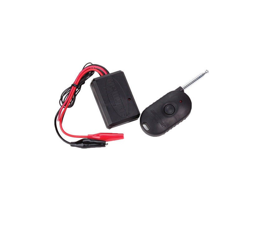
The Feeder Activator allows a feeder motor to be remotely activated from up to 300 feet away. The Feeder Activator consists of a Receiver that mounts in your wildlife feeder and a Handheld Transmitter. When the button is pressed on the Transmitter, a signal is sent to the Receiver which activates the Feeder motor for a period of five seconds. The Transmitter is powered from a 12-volt Remote Control Battery and the Receiver is powered from your 6-volt Feeder Battery. The Feeder Activator works with most 6-volt wildlife feeders that meet the following requirements:
- a) When the battery is installed in the feeder, the positive and negative contacts are exposed and accessible enabling the connection of the Feeder Activator power wires (with alligator clips).
- b) The two wires that run between the feeder circuit board and the motor are accessible – enabling the connection of the Feeder Activator motor wires.NOTE: On Moultrie feeder kits, there are two separate wires labeled “Feeder Activator Connection” that should be used for connection. The Feeder Activator may be used in a metal Feeder enclosure if the Antenna Wire can be routed outside the box.


WIRING THE RECEIVER NON-MOULTRIE KIT
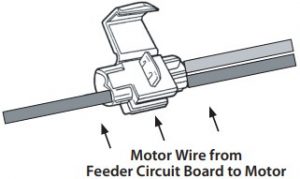
- Disconnect the battery from the Feeder. Holding one of the provided Connectors in the orientation shown, push the Receiver’s Red Motor Wire into the rear hole until it reaches the internal stop.
- Slide the positive wire that runs between the Feeder’s circuit board and the motor into the side of the Connector as shown. The positive wire may be red in color, marked “positive”, or not identified. If it is not identified, select either wire.
- With pliers, squeeze the metal contact tab down until it is even with the surface of the plastic. Close the Plastic Cover until it snaps into place.
- Repeat steps 1 through 3 for the Black Negative Wire.


WIRING THE RECEIVER – MOULTRIE FEEDER KIT
If installing on a Moultrie feeder kit, locate the separate wires labeled “Feeder Activator Connection +/-” as shown in the photo. Use the steps from Section B1 to install the receiver wires onto these activator wires. This will prevent you from compromising the wires that run between the timer circuit board and the the motor on your feeder kit.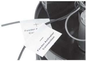
CHECKING CONNECTIONS
- Connect the battery to the Feeder and then to the Receiver. Connect the Red Wires to the positive terminal (+) and the Black Wires to the negative (-) terminal.
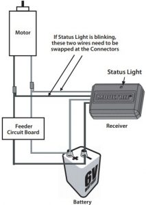
- Immediately following connection of the battery, the red Status Light on the Receiver will be on solid or blinking:STATUS LIGHT SOLIDTo test the Feeder Activator, stand back from the feeder and press the button on the Transmitter. Feeder motor will run for a period of five seconds. If motor does not run, check connections to Battery and to motor as shown.STATUS LIGHT BLINKINGOpen the Plastic Cover on the Connectors and carefully pry open with a screwdriver. Pull-up on metal clip with pliers to release the wires. Swap the motor wires as shown. Refer back to Section B for details on connection.
MOUNTING RECEIVER
- Remove the protective cover from the double sided tape on the back of the Receiver. Position the Receiver on a clean and dry location inside the Feeder.
- Route the black Antenna Wire inside the plastic Feeder enclosure. The Antenna Wire should not be folded or in contact with the motor. If using the Feeder Activator in a metal Feeder enclosure, the Antenna Wire must be routed outside the box in an area that is not accessible by varmints.
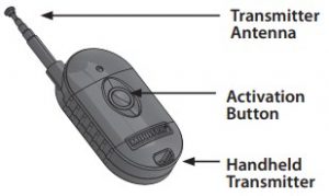
OPERATING UNIT
To activate the Feeder motor for a period of five seconds, fully extend the Transmitter Antenna and hold the Activation Button until the Feeder runs.
FCC COMPLIANCEThis device complies with part 15 of the FCC Rules. Operation is subject to the following two conditions:
- This device may not cause harmful interference, and
- This device must accept any interference received, including interference that may cause undesired operation.
For devices approved under Part 15, the user’s manual or instruction manual for an intentional or unintentional radiator shall caution the user about changes or modifications to the device (Section 15.21).NOTE: This equipment has been tested and found to comply with the limits for a Class B digital device, pursuant to part 15 of the FCC Rules. These limits are designed to provide reasonable protection against harmful interference in a residential installation. This equipment generates, uses and can radiate radio frequency energy and, if not installed and used in accordance with the instructions, may cause harmful interference to radio communications. However, there is no guarantee that interference will not occur in a particular installation. If this equipment does cause harmful interference to radio or television reception, which can be determined by turning the equipment off and on, the user is encouraged to try to correct the interference by one or more of the following measures:Reorient or relocate the receiving antenna. Increase the separation between the equipment and receiver. Connect the equipment into an outlet on a circuit different from that to which the receiver is connected. Consult the dealer or an experienced radio/TV technician for help.Our Service Department will gladly answer any questions you have. www.moultriefeeders.com/support
References
[xyz-ips snippet=”download-snippet”]