User Manual
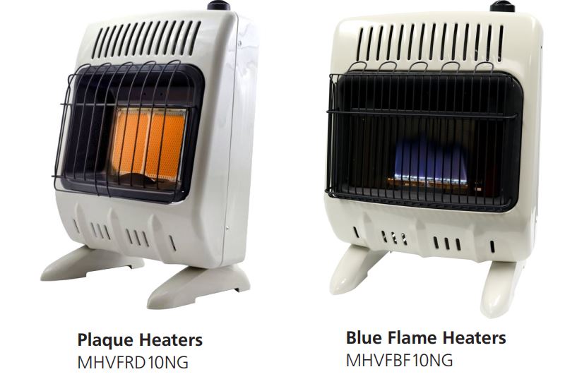
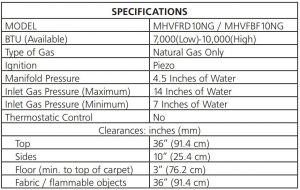
MR.Heater MHVFRD10NG and MHVFBF10NG Unvented Natural Gas Fired Room Heater
INSTALLER: Leave this manual with the appliance.CONSUMER: Retain this manual for future reference.
 WARNING: If the information in this manual is not followed exactly, a fire or explosion may result causing property damage, personal injury, or loss of life.–
- Do not store or use gasoline or other flammable vapors and liquids in the vicinity of this or any other appliance.
WHAT TO DO IF YOU SMELL GAS
- Do not try to light any appliance.
- Do not touch any electrical switch; do not use any phone in your building.
- Immediately call your gas supplier from a neighbor’s phone. Follow the gas supplier’s instructions.
- If you cannot reach your gas supplier, call the fire department.
Installation and service must be performed by a qualified installer, service agency or the gas supplier.
This is an unvented gas-fired heater. It uses air (oxygen) from the room in which it is installed.Provisions for adequate combustion and ventilation air must be provided. Refer to Fresh Air forCombustion and Ventilation section on page 4 of this manual.
This appliance may be installed in an aftermarket permanently manufactured (mobile) home,where not prohibited by local codes.
This appliance is only for use with the type of gas indicated on the rating plate. This appliance isnot convertible for use with any other gas.
WARNING: FIRE, EXPLOSION, AND ASPHYXIATION HAZARDImproper installation, adjustment, alteration, service or maintenance can cause injury or property damage. Refer to this manual for correct installation and operational procedures. For assistance or additional information consult a qualified installer, service agency, or gas supplier.
Read and follow instructions and precautions in User’s Information Manual provided with thisheater.
Due to high temperatures, heater should be kept out of traffic and away from furniture and draperies.
Do not place clothing or other flammable material on or near the appliance.
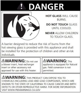
Children and adults should be alerted to the hazard of high surface temperature and should stay away to avoid burns or clothing ignition.
Young children should be carefully supervised when they are in the same room with heater.
A barrier designed to reduce the risk of burns from the hot viewing glass is provided with this appliance and shall be installed for the protection of children and other at-risk individuals.
If the barrier becomes damaged, the barrier shall be replaced with the manufacturer’s barrier for this appliance.Any safety screen or guard removed for servicing an appliance must be replaced prior to operating the heater.
Installation and repair should be done by a qualified service person. The appliance should be inspected before use and at least annually by a professional service person. More frequent cleaning may be required due to excessive lint from carpeting, bedding material, etc. It is imperative that control compartments, burners, and circulating air passageways of the appliance be kept clean.
In order to provide the best service possible Mr. Heater is now giving you more ways to get in touch with us: WEBSITE: Mr. Heater’s full line of product are now at: www.mrheater.com

**Operating heater above elevations of 4,500 feet could cause pilot/ODS to shutdown heater.**
PRECAUTIONS:
- Either of the 10,000 BTU (2931 W) units (the MHVFRD10NG or the MHVFBF10NG) may be installed in a bedroom, but shall not be installed in a bathroom or any place where a strong wind would shut down the appliance.
- This heater needs outside ventilation air to run properly. The Oxygen Depletion Sensor (ODS) safety shutoff system shuts down the heater if not enough fresh air is available. See Fresh Air for Combustion and Ventilation, page 4.
- Keep all air openings in heater clear, free of debris or any blockage. This will ensure that enough air for proper combustion enters the heater.
- If heater shuts off, do not relight until you provide fresh, outside air. If heater keeps shutting off, it requires servicing.
- Turn off and let cool before servicing. Only a qualified service person should service and repair heater.
- Do not run heater:• Where flammable liquids or vapors are used or stored• During dusty conditions.
- Before using furniture polish, wax, carpet cleaner or similar products, turn heater off. If heated the vapors from these products may create a white powder residue within burner box or on adjacent walls or furniture.
- Do not use heater if any part has been underwater. Immediately call a qualified service technician to inspect the room heater and to replace any part of the control system and any gas control which has been underwater.
- Operating heater above elevations of 4,500 feet could cause pilot/ODS to shutdown heater.
- Always run heater with control knob in a locked position. Never set control knob between locked positions. Poor combustion and higher levels of carbon monoxide may result if control knob is left between locked positions
DANGER: Carbon monoxide poisoning may lead to death.Carbon
Monoxide Poisoning:Early signs of carbon monoxide poisoning resemble the flu, with headaches, dizziness, or nausea. If you have these signs, the heater may not be working properly. Get fresh air at once! Have heater serviced. Some people are more affected by carbon monoxide than others. These include pregnant women, persons with heart or lung disease or anemia, those under the influence of alcohol, and those at high altitudes.
Natural Gas:Natural gas is odorless. An odor making agent is added to natural gas. The odor helps you detect a natural gas leak. However, the odor added to the gas can fade. Gas may be present even though no odor exists. Make certain you read and understand all warnings. Keep this manual for reference. It is your guide to safe and proper operation of this heater.
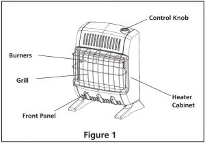
Product Features
SAFETY DEVICEThis heater has a pilot with an Oxygen Depletion Sensor (ODS) safety shut off system. The ODS/pilot shuts off the heater if there is not enough fresh air.
IGNITION SYSTEMPIEZO: The heater is equipped with a piezo manual ignitor. This system requires no matches, batteries, or other source to light heater.
LOCAL CODESInstall and use heater with care.Installation must conform to local codes or in the absences of local codes, use the latest edition of National Fuel Gas Code, ANSI Z223.1/NFPA 54.
UNPACKING
- Remove heater from carton.
- Remove all protective packaging applied to heater for shipment.
- Check heater for any shipping damage. If heater is damaged, promptly inform dealer where you bought heater.
FRESH AIR FOR COMBUSTION AND VENTILATION
WARNING: This heater shall not be installed in a confined space or unusually tight construction unless provisions are provided for adequate combustion and ventilation air. Read the following instructions to insure proper fresh air for this and other fuel-burning appliances in your home.
ESTABLISHING ADEQUATE VENTILATION
The following are excerpts from National Fuel Gas Code, NFPA 54/ ANSI Z223.1, Section 5.3, Air for Combustion and Ventilation. All spaces in homes fall into one of the three following ventilation classifications:
- Unusually Tight Construction
- Unconfined Space
- Confined Space
This heater must not be installed in a confined space or unusually tight construction unless provisions are provided for adequate combustion and ventilation air. The information on pages 4 and 5 will help you classify your space and provide adequate ventilation.
Unusually Tight ConstructionIf your home meets all of the three following criteria you must provide additional fresh air. See Ventilation from Outdoors, page 5. Unusually tight construction is defined as construction where:
- Walls and ceilings exposed to the outside atmosphere have a continuous water vapor retarder with a rating of one perm (6 x 10-11 kg per pa-sec-m2) or less with openings gasketed or sealed and
- Weather stripping has been added on operable windows and doors, and
- Caulking or sealants are applied to areas such as joints around windows and door frames, between wallceiling joints, between wall panels, at penetrations for plumbing, electrical, and gas lines, and at other openings.
If you home does not meet all of the three criteria above, see Determining the Type of Heater Location Space, below.
Confined Space and Unconfined SpaceThe National Fuel Gas Code, NFPA 54/ ANSI Z223.1 defines a confined space as a space whose volume is less than 50 cubic feet per 1,000 Btu per hour (4.8 m3 per kW) of the aggregate input rating of all appliances installed in that space, and an unconfined space as a space whose volume is not less than 50 cubic feet per 1,000 Btu per hour (4.8 m3 per kW) of the aggregate input rating of all appliances installed in that space. Rooms communicating directly with the space in which the appliances are installed*, through openings not furnished with doors, are considered a part of the unconfined space.
*Adjoining rooms are communication only if there are doorless passageways or ventilation grills between them.
DETERMINING THE TYPE OF HEATER LOCATION SPACE:
Use this method to determine if you have a confined or unconfined space.
Note: the space includes the room in which you install heater plus any adjoining rooms with door less passageways or ventilation grills between the rooms.
- Find the volume of the space by multiplying room length x width x height. Example: Space size 18ft (length) x 18ft. (width) x 8ft. (height) = 2592 If additional ventilation to adjoining room is supplied with grills or openings, add the volume of these rooms to the total volume of the space.
- Divide the space volume by 50 cubic feet to determine the maximum Btu/hr the space can support. Example: 2592 cu.ft. (volume of space) / 50 cu.ft. = 51.8 or 51,800 (maximum Btu/hr the space can support).
 WARNING: This heater shall not be installed in a room or space unless the required volume of indoor combustion air is provided by the method described in the National Fuel Gas Code, ANSI Z223.1/NFPA 54, the International Fuel Gas Code, or applicable local codes.
 - Add the Btu/hr of all the fuel-burning appliances in the space such as, Vent–free heater, Gas water heater, Gas furnace, Vented gas heater, Gas fireplace logs, and Other gas appliances**Do not include direct-vent gas appliances. Direct-vent draws combustion air from the outdoors and vents to the outdoors.Example:Gas water heater 40,000 Btu/hrVent Free Heater + 20,000 Btu/hrTotal =60,000 Btu/hr
- Compare the maximum Btu/hr the space can support with the actual amount of Btu/hr used.Example: 51,800 Btu/hr (maximum Btu/hr the space can support) 60,000 Btu/hr (Actual amount of Btu/hr used)The space in the above example is a confined space because the actual Btu/hr used is more than the maximum Btu/hr the space can support.
You must provide additional fresh air. Your options are as follows:
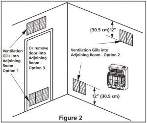
- Rework worksheet, and the space of an adjoining room. If the extra space provides an unconfined space, remove door to adjoining room or add ventilation grills between the rooms. See Ventilation From Inside Building (Fig. 2)
- Vent room directly to the outdoors. See Ventilation From Outdoors (Fig. 3).
- Install a lower Btu/hr heater if lower Btu/hr size makes room unconfined.If actual Btu/hr used is less than the maximum Btu/ hr the space can support, the space is an unconfined space. You will need no additional fresh air ventilation.
VENTILATION AIR
Ventilation from Inside BuildingThis fresh air would come from an adjoining unconfined space. When ventilation to an adjoining unconfined space, you must provide two permanent openings: one within 12” of the ceiling and one within 12” of the floor on the wall connecting the two spaces (see options 1 & 2 of figure 2). You can also remove door into adjoining room (see option3, fig 2). Follow the National Fuel Gas Code NFPA 54/ ANSI Z223.1, Section 5.3, Air for Combustion and Ventilation for required size of ventilation grills or ducts. WARNING: Rework worksheet, adding the space of the adjoining unconfined space. The combined space must have enough fresh air to supply all appliance in both spaces.
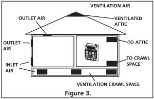
Ventilation from OutdoorsIf necessary provide extra fresh air by using ventilation grills or ducts. Connect these items directly to the outdoors or spaces open to the outdoors. These include attics* and crawl spaces. Follow the National Fuel Gas Code NFPA 54/ ANSI Z223.1, Section 5.3, Air for Combustion and Ventilation for required size of ventilation grills or ducts.
*IMPORTANT: Do not provide openings for inlet or outlet into attic. If attic has a thermostat-controlled power vent, heated air entering the attic will activate the power vent. IMPORTANT: Vent-free heaters add moisture to the air. Although this is beneficial, installing heater in rooms without enough ventilation air may cause mildew to form from too much moisture. See Fresh Air for Combustion and Ventilation, pages 4 through 5.
INSTALLATION
WARNING: Any change to this heater or its controls can be dangerous.
NOTICE: This heater is intended for the use as supplemental heat. Use this heater along with your primary heating system. Do not install this heater as your primary heat source. If you have a central heating system, you may run system’s circulating blower while using heater. This will help circulate the heat throughout the house. In the event of a power outage, you can use this heater as your primary heat source for the duration of the outage.
WARNING:A qualified service person must install heater. Follow all local codes.
CHECK GAS TYPEUse only natural gas. If your gas supply is not natural gas, do not install heater. Call dealer where you bought heater for proper type heater.
THIS INSTALLATION REQUIRES:Before installing heater, make sure you have the items listed below:
- Piping (check local codes)
- Sealant (resistant to natural gas)
- Equipment shutoff valve*
- Ground joint union
- Test gauge connection*
- Sediment trap
- Tee joint
- Pipe wrench
*A CSA/AGA certified equipment shutoff valve with 1/8” NPT tap is an acceptable alternative to test gauge connection. Purchase a CSA/AGA certified equipment shutoff valve from your dealer.
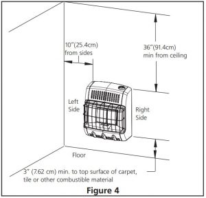
LOCATING HEATERThis heater is designed to be mounted on the wall. The heater can also be located on a non-combustible floor, away from a wall by using the floor mounting stands included with the heater. If installed on combustible flooring such as carpeting, tile or other combustible material other than wood flooring, the heater must be placed on a metal or wood panel extending the full width and depth of the appliance.
For convenience and efficiency, install the heater:
- Where there is easy access for operation, inspection, and service.
- In the coldest part of the room.
CAUTION: If you install the heater in a home garage:
- Heater pilot and burner must be at least 18 inches above floor.
- Locate heater where moving vehicle will not hit it.
CAUTION:This heater creates warm air currents. These currents move heat to wall surfaces next to heater. Installing heater next to vinyl or cloth wall covering or operating heater where impurities (such as tobacco smoke, aromatic candles, cleaning fluids, oil or kerosene lamps, etc.) are present inthe air may discolor walls.
WARNING:Never install the heater:
- In a recreational vehicle.
- Where curtains, furniture, clothing, or other flammable objects are less than 36 inches from the front, top, or sides of the heater.
- As a fireplace insert
- In high-traffic areas
- In windy or drafty areas
WARNING:Heater must be mounted to maintain the minimum clearances shown in Figure 4. If possible, provide greater clearances from the floor, ceiling, and joining walls.
FASTENING HEATER TO WALL
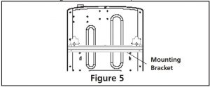
Mounting BracketThe mounting bracket in located on the back panel of heater (see figure 5). It has been taped there for shipping. Remove mounting bracket from back panel.
Removing Front Panel of Heater
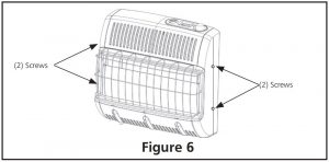
- Remove (4) screws total there are (2) screws on either side of the heater. (Figure 6)
- Pull the front panel and back panel apart.
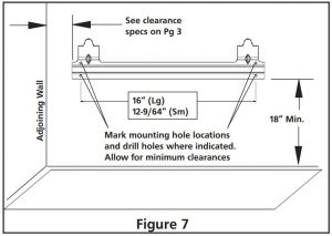
Attaching Mounting Bracket to WallUse holes on each end of mounting bracket to attach bracket to wall. These holes are 16 inches apart. Attach mounting bracket to wall in one of two following ways.
- Attach to wall studs
- Attach to wall anchor
Attaching to Wall Stud:This way is the best providing the strongest mounting in wood frame houses.
Attaching to Wall Anchor:This way allows you to attach mounting bracket to hollow walls (wall areas between studs) or to solid walls (concrete or masonry).
Decide which way best suits your needs. Either method will provide a secure hold for the mounting bracket.
- Tape mounting bracket to wall where heater will be located. Make sure mounting bracket is level. For wall stud mounting locate one end of the mounting bracket over a wall stud. WARNING: Maintain minimum clearances shown in figure 7. If you can, provide greater clearances from the floor and joining wall.
- Mark screw locations on wall (see figure 7).
- Remove tape and mount bracket from wall.
Attaching to Wall Stud:For attaching mounting bracket to wall studs
- Drill holes at marked locations using 9/64” drill bit.
- Place mounting bracket onto wall. Line up holes on each end of bracket with hole drilled in wall.
- Insert mounting screws through bracket and into wall studs.
- Tighten screws until mounting bracket is firmly fastened to wall studs.
Attaching to Wall using Anchor:For attaching mounting bracket to hollow walls (wall areas between studs) or solid walls (concrete or masonry)
Note: Wall anchors, mounting screws, and spacer are in hardware package. The hardware package is provided with heater.
- Drill holes at marked locations using 5/16” drill bit. For solid walls (concrete or masonry), drill at least 1” deep.
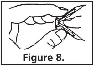
- Fold wall anchor as shown in figure 8 below.
- Insert wall anchor (wings first) into hole. Tap anchor flush to wall.
- For thin walls (1/2” or less) insert red key into wall anchor.
- Place mounting bracket onto wall. Line up holes on each end of bracket with wall anchors.
- Insert mounting screws through bracket and into wall anchors.
- Tighten screws until mounting bracket is firmly fastened to wall.
Placing Heater on Mounting Bracket
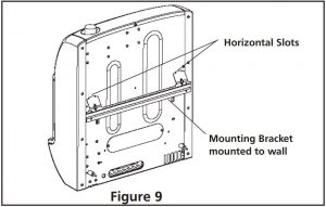
- Locate two horizontal slots on back pane of heater (see figure 9).
- Place heater onto mounting bracket. Slide horizontal slots onto stand-out tabs on mounting bracket.
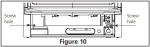
Installing Bottom Mounting Screws
- Locate two bottom mounting holes. These holes are near bottom on back panel of heater (see figure 10).
- Mark screws locations on wall.
- Remove heater from mounting bracket.
- If installing bottom mounting screw into hollow or solid wall, install wall anchors. Follow steps 1 through 4 under Attaching to Wall using Anchor. If installing bottom mounting screw into wall stud, drill holes at marked locations using 9/64” drill bit.
- Re-place heater onto mounting bracket.
- Place spacers between bottom mounting holes and wall anchor or drilled hole.
- Hold spacer in place with one hand. With the other hand, insert mounting screw through bottom mounting hole and spacer. Place tip of screw in opening of wall anchor or drilled hole.
- Tighten both screws until heater is firmly secured to wall. Do not over tighten.
Note: Do not re-place front panel at this time. Replace front panel after making gas connections and checking for leaks.
FLOOR MOUNTING AWAY FROM WALL:
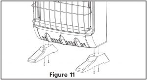
Installing Support Feet (See figure 11.)
- Lay heater onto table on its back with bottom edge overhanging table edge.
- Securely attach feet to bottom of heater using 2 – self-tapping screws each Note: Feet should have long end going out the front of heater, and the edge coinciding with side of heater. If feet overhang side of the heater, switch leg location.
- Place heater on non-combustible surface (see Locating Heater, page 6) before proceeding with gas connection. If this will be a permanent location, heater may be locked into position using anchoring holes in mounting feet.
 Note: Feet should have long end going out the front of heater, and the edge coinciding with side of heater. If feet overhang side of the heater, switch leg location.
Note: Use of floor mounting feet will require you to use a 3/8 NPT street elbow to make gas connection.
CONNECTING TO GAS SUPPLYWARNING: A qualified service person must connect heater to gas supply. Follow all local codes.
WARNING:This appliance requires a 3/8” NPT (National Pipe Thread) inlet connection to the pressure regulator. Use of floor mounting feet will require you to use a 3/8 NPT street elbow to make gas connection.
CAUTION: Never connect heater to private (non utility) gas well. This gas is commonly known as wellhead gas.
IMPORTANT: Check your gas line pressure before connecting heater to gas line. Gas line pressure must be no greater than 14 inches of water. If gas line pressure is higher, heater regulator damage could occur.
CAUTION: Use only new black iron or steel pipe. Internally-tinned copper tubing may be used in certain areas. Check your local codes. Use pipe of large enough diameter to allow proper gas volume to heater. If pipe is too small, undue loss of pressure will occur.
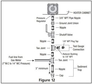
Installation must include an equipment shutoff valve, union and plugged 1/8” NPT tap. Locate NPT tap within reach of test gauge hookup. NPT tap must be upstream from heater (see figure 12).
*A CSA/AGA certified equipment shutoff valve with 1/8” NPT tap is an acceptable alternative to test gauge connection. Purchase the CSA/AGA certified equipment shutoff valve from your dealer.
IMPORTANT: Install an equipment shutoff valve in an accessible location. The equipment shutoff valve is for turning on or shutting off the gas to the appliance. Apply pipe joint sealant lightly to male threads. This will prevent excess sealant from going into pipe. Excess sealant in pipe could result in clogged heater fuel train.
CAUTION: Use pipe joint sealant that is resistant to natural gas.Install sediment trap in supply line as shown in figure 12. Locate sediment trap where it is within reach for cleaning. A sediment trap traps moisture and contaminants. This keeps them from going into heater. If sediment trap is not installed or is installed improperly, heater may not run correctly.
IMPORTANT: Hold pressure regulator with wrench when connecting it to gas piping and/or fittings.
CHECKING GAS CONNECTIONS
WARNING: Test all gas piping and connections for leaks after installing or servicing. Correct all leaks at once.
WARNING: Never use an open flame to check for a gas leak. Apply a mixture of liquid soap and water to all joints. Bubbles forming show a leak. Correct all leaks at once.
PRESSURE TESTING GAS SUPPLY PIPING SYSTEM
High PressureTest pressure in Excess of ½ psig (3.5kPa)
- The appliance and its appliance main gas valve must be disconnected from the gas supply piping system during any pressure testing of that system at test pressures in excess of ½ psi (3.5 kPa). The appliance must be isolated from the gas supply piping system by closing its equipment shutoff valve during any pressure testing of the gas supply piping system at test pressures equal to or less than ½ psi (3.5 kPa).
- Cap off open end of gas pipe where equipment shutoff valve was connected. Pressurize supply piping system by either using compressed air or opening main gas valve on or near gas meter.
- Check all connections and joints in gas supply piping system. Apply mixture of liquid soap and water to gas joints. Bubbles forming show a leak.
- Correct all leaks at once.
- Depressurize and relieve pressure in supply piping system.
- Reconnect heater and equipment shutoff valve to gas supply.
- Reconnected fittings must be checked for leaks in next section.
Low PressureTest Pressure Equal To or Less Than ½ psig (3.5 kPa)
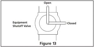
- Close equipment shutoff valve (see figure 13)
- Pressurize supply piping system by either using compressed air or opening main gas valve on or near gas meter.
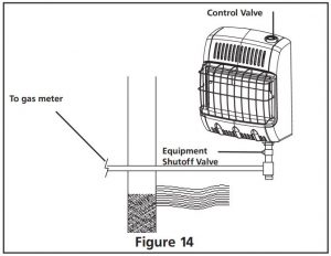
- Check all joints from the gas meter to equipment shutoff valve (see figure 14). Apply mixture of liquid soap and water to gas joints. Bubbles forming show a leak.
- Correct all leaks at once.
- Depressurize and relieve pressure from supply piping system.
Pressure Testing Heater Gas Connections:
- Make sure that the heater supply piping system is connected and has been leak tested as described above.
- Make sure control knob of heater is in OFF position.
- Open equipment shutoff valve (see figure 13).
- Open natural gas supply valve.
- Check all joints from equipment shutoff valve to control valve (see figure 14). Apply mixture of liquid soap and water to gas joints. Bubbles forming show a leak.
- Correct all leaks at once.
- Light heater (see Operating Your Heater, page page 10.
- Turn off heater (see To Turn OFF Gas to Appliance, page 10.
- Replace lower front panel.
OPERATING YOUR HEATER
FOR YOUR SAFETY READ BEFORE LIGHTING
WARNING: If you do not follow these instructions exactly, a fire or explosion may result causing property damage, personal injury or loss of life.
A. This appliance has a pilot that must be lighted by hand. When lighting the pilot, follow these instructions exactly.B. BEFORE LIGHTING smell all around the appliance area for gas. Be sure to smell next to the floor because some gas is heavier than air and will settle on the floor.
WHAT TO DO IF YOU SMELL GAS
- Shut off gas supply.
- Do not try to light any appliance.
- Do not touch any electrical switch; do not use any phone in your building.
- Immediately call you gas supplier from a neighbor’s phone. Follow the gas supplier’s instructions.
- If you can not reach your gas supplier, call the fire department.
C. Use only your hand to push in or turn the gas control knob. Never use tools. If knob will not push in or turn by hand, don’t try to repair it; call a qualified service technician or gas supplier. Force or attempted repair may result in a fire or explosion.D. Do not use this appliance if any part has been underwater. Immediately call a qualified service technician to inspect the appliance and to replace any part of the control system which has been under water.
LIGHTING INSTRUCTIONS
- STOP! Read the all safety information included with and on the side of heater.
- Check that gas supply to heater is on.
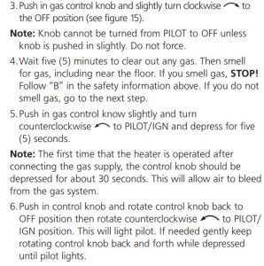
7. Keep control knob depressed in for ten (10) seconds after lighting pilot. If pilot goes out, repeat steps 4, 5, 6 and 7.If pilot does not stay lit, refer to Troubleshooting, pages 12-13. Also, contact a qualified service person or gas supplier for repairs.If control knob does not pop up when released, contact a qualified service person or gas supplier for repairs.
8. FOR MHVFRD10NG:
- Turn control knob to “HI” to light heater. Leave on “HI” position until the tiles have turned bright orange.
- After the burner tiles have turned bright orange, adjustheat output by turning Control Knob to desired position (“LO” or “HI”).
FOR MHVFBF10NG:
- When the pilot is lit, turn the control knob to “HI” position to light.
- After flame is established on “HI”, adjust heat output by turning control knob to desired position (“LO” or “HI”). Do not operate heater between locked positions.
CAUTION: Do not try to adjust heating level by using equipment shutoff valve.
WARNING: When running heater, set control knob at “LO” or “HI” locked positions. Poor combustion and higher levels of carbon monoxide may result if heater is operated with control knob positioned between locked positions.
IMPORTANT: Release downward pressure while turning control knob. Control knob must be locked at the desired position.
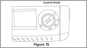
TO TURN OFF GAS TO APPLIANCE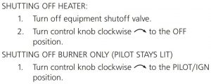
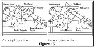
INSPECTING BURNERCheck pilot flame pattern and burner flame pattern often.
PILOT FLAME PATTERNFigure 16 show a correct pilot flame pattern and also shows an incorrect pilot flame pattern. The incorrect pilot flame pattern is not touching thermocouple. This will cause the thermocouple to cool. When the thermocouple cools, the heater will shut down. If pilot flame pattern is incorrect, as shown in Figure 16:
- Turn heater off (see To Turn OFF Gas to Appliance, page 10)
- See Troubleshooting, pages 12-13.
CLEANING AND MAINTENANCE
WARNING: Turn off heater and let cool before servicing.For maintenance of the inside cabinet or to access the burner and pilot assembly for cleaning or service. Remove the four screws(two located on each side) that secure the front shell to the unit (Figure 6). Gently lift up on the front shell to disengage the hooks and pull forward to remove it. You will now be able to access all of the internal components of the appliance.
CAUTION: You must keep control areas, burner and circulation air passageways of heater clean. Inspect these areas of heater before use. Have the heater inspected yearly by a qualified service person. Heater may need more frequent cleaning due to excess lent from carpeting, bedding material, pet hair, etc.
Make sure grille guard is in place before running heater. If screen or grille guard is removed for servicing it must be replaced prior to operating the heater.
WARNING:Failure to keep the primary air opening(s) of the burner(s) clean may result in sooting and property damage.
CLEANING ODS/PILOT AND BURNER
- Use as vacuum cleaner, pressurized air or small soft bristled brush to clean.
CLEANING BURNER PILOT AIR HOLE INLETWe recommend that you clean the unit every 2,500 hours of operation or every three months. We also recommend that you keep the burner tube and pilot assembly clean and free of dust and dirt. To clean these parts we recommend using compressed air no greater than 30 psig.
This can be done by using a vacuum cleaner in the blow position or using compressed air in a can. If using canned air please follow the directions on the can. If you don’t follow directions on the can you could damage the burner or pilot assembly. In addition, the directions below should also be followed.
- Shut off the unit, including the pilot. Allow the unit to cool for at least thirty minutes.
- Inspect burner and pilot for dust and dirt.
- Blow air through the port/slots and holes in the burner.
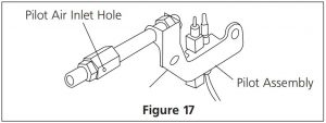
A yellow tip on the pilot flame indicates dust and dirt in the pilot assembly. To clean the pilot assembly find the small pilot air inlet hole about two inches from where the pilot flame comes out of the pilot assembly (see figure 17). With the unit off, lightly blow air through the air inlet hole. You may blow through a drinking straw if compressed air is not available.
CLEANING HEATER CABINET
Air passageways
- Use a vacuum cleaner or pressurized air to clean Exterior
- Use a soft cloth dampened with a mild soap and water mixture. Wipe the cabinet to remove dust.
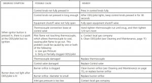
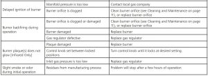
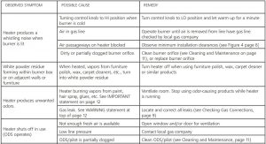
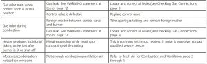
TROUBLESHOOTING
NOTE: All troubleshooting items are listed in order of operation and likely occurrence. WARNING: Only a qualified service person should service and repair heater.
CAUTION: Never use a wire needle, or similar object to clean ODS/pilot. This can damage ODS/pilot unit.Make sure grille guard is in place before running heater. If screen or grille guard is removed for servicing it must be replaced prior to operating the heater.
WARNING: If you smell gas:
- Shut off gas supply
- Do not try to light any appliance
- Do not touch any electrical switch; do not use any phone in your building
- Immediately call you gas supplier from a neighbor’s phone. Follow the gas supplier’s instructions.
- If you cannot reach your gas supplier, call the fire department.
IMPORTANT:Operating heater where impurities in air exist may create odors. Cleaning supplies, paint, paint remover, cigarette smoke, cements and glues, new carpet or textiles, etc., create fumes. These fumes may mix with combustion air and create odors and possible discoloration of walls and ceilings.
LIMITED WARRANTYMr. Heater, Inc. warrants its heaters and accessories to be free from defects in material andworkmanship for a period of 1 year from date of purchase. Mr. Heater, Inc. will repair orreplace this product free of charge if it has been proven to be defective within the 1-yearperiod, and is returned at customer expense with proof of purchase to Mr. Heater, Inc.within the warranty period.
This warranty gives you specific legal rights, and you may also have other rights whichvary from state to state.
Mr. Heater, Inc. reserves the right to make changes at any time, without notice or obligation,in colors, specifications, accessories, materials and models.
PRODUCT REGISTRATION: Thank you for your purchase.Please log in to http://www.egiregistration.com to register your product.
Mr. Heater, INC., 4560 W. 160TH ST., CLEVELAND, OHIO 44135 • 800-251-0001Mr. Heater is a registered trademarks of Mr. Heater, Inc.© 2020, Mr. Heater. All rights reserved
MR.Heater MHVFRD10NG and MHVFBF10NG Unvented Natural Gas Fired Room Heater User Manual – MR.Heater MHVFRD10NG and MHVFBF10NG Unvented Natural Gas Fired Room Heater User Manual –
Questions about your Manual? Post in the comments!
[xyz-ips snippet=”download-snippet”]