NEVER LEAVE THE HEATER UNATTENDED WHILE BURNING!
| OPERATING INSTRUCTIONS AND OWNER’S MANUAL | ||
 |
PORTABLE BIG BUDDYRADIANT HEATER
|
Model # |
| MH18B | ||
| READ INSTRUCTIONS CAREFULLY: Read and follow all instructions. Place instructions in a safe place for future reference. Do not allow anyone who has not read these instructions to assemble, light, adjust or operate the heater. |
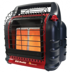
Use only Mr. Heater branded accessories (See page 10 for WARNING information
LANGUAGES INCLUDED:•ENGLISH•FRENCH
|
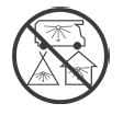
CARBON MONOXIDE HAZARDThis appliance can produce carbon monoxide which has no odor.Using it in an enclosed space can kill you.Never use this appliance in an enclosed space such as a camper, tent, car or home.
|
|
  |
www.mrheater.com ![]()
![]()
NEVER LEAVE THE HEATER UNATTENDED WHILE BURNING!
This Page Intentionally Left Blank
NEVER LEAVE THE HEATER UNATTENDED WHILE BURNING!
![]()
![]()
![]()
![]()
![]()
![]()
![]()
![]()
![]()
![]()
![]()
![]()
![]()
![]()
![]()
|
|
|
|
CONTENTSGeneral Safety Instructions………………………………………… 3General Information…………………………………………………. 4Operating with Disposable Propane Cylinders……………….. 5Operating With Hose Connected to Remote Cylinder…….. 6Maintenance…………………………………………………………… 7Troubleshooting………………………………………………………. 7Parts List…………………………………………………………………. 8Parts Ordering Information………………………………………. 10Service Information…………………………………………………. 10SPECIFICATIONSMODEL NO……………………………………………… MH18BGAS TYPE………………………………………………PROPANEINPUT BTU/HR……………………..4,000 / 9,000 /18,000CLEARANCE TO COMBUSTIBLESTOP……………………………………………………………… 30”FRONT………………………………………………………….. 24”SIDES…………………………………………………………….. 6”REAR……………………………………………………………… 0”
•Some carpets or linoleum surfaces may discolor if heater isplaced directly on these floor coverings.•When operating the heater at altitudes over 7,000 FT above sealevel the heater may shut off. (Please read the GENERAL INFORMATION)Mr. Heater | Big Buddy
GENERAL SAFETY INSTRUCTIONSTHIS IS A HEATING APPLIANCE. DO NOT OPERATETHIS APPLIANCE WITHOUT THE FRONT WIRE GUARDINSTALLED. DO NOT ATTEMPT TO WARM OR COOKFOOD ON THIS HEATER.
• Do not use non-approved attachments on this heater.• Due to high temperatures, the appliance should be locatedout of traffic and away from combustible materials.• Children and adults should be alerted to the hazardof high surface temperatures and should stay away toavoid burns or clothing ignition.• Young children should be carefully supervised whenthey are near the appliance.• Do not place clothing or other flammable material on ornear the appliance.• Do not operate heater in any moving vehicle.• This heater requires a vent area of 18 square inches(example 4 1/4” x 4 1/4” opening) minimum for adequateventilation during operation. Do not use other fuel burningappliances inside.• GAS PRESSURE AT HEATER IS REGULATED AND FIXED AT11” W.C. WHEN USING A REMOTE HOSE CONNECTIONTO HEATER TANK SWIVEL(S), DO NOT REGULATE ORREDUCE PROPANE TANK SUPPLY PRESSURE TO HEATER.• WARNING: ANY HOSE CONNECTION TO A QUICK DISCONNECTFITTING ON HEATER MUST BE REGULATEDTO 11” W.C. PRESSURE• REGULATOR IN HEATER MUST ALWAYS BE IN PLACEDURING OPERATION.• Any safety screen or guard removed for servicing the appliancemust be replaced prior to operating the heater.
Operating Instructions and Owner’s Manual
NEVER LEAVE THE HEATER UNATTENDED WHILE BURNING!
• The appliance should be inspected before each use.Frequent cleaning may be required. The control compartments,burner(s) and circulating air passageways ofthe appliance must be kept clean, see MAINTENANCE.• DO NOT use this heater if any part has been underwater. Immediately call a qualified service technician toinspect the heater and to replace any part of the controlsystem and any gas control, which has been underwater.• When used without adequate combustion and ventilationair, this heater may give off excessive CARBONMONOXIDE, an odorless, poisonous gas.• Some people – pregnant women, persons with heartor lung disease, anemia, those under the influence ofalcohol, those at high altitudes – are more affected bycarbon monoxide than others.• When heater is placed on the ground, make sure theground is level and keep any objects at least 24 inchesfrom the front of the heater. THIS HEATER IS EQUIPPEDWITH A TIP OVER SWITCH THAT WILL SHUT THEHEATER OFF IF THE HEATER TIPS OVER.HOWEVER,DO NOT LEAVE HEATER UNATTENDED OR WHERECHILDREN MAY CAUSE THE HEATER TO TIP OVER.NEVER OPERATE THE HEATER WHILE SLEEPING!
![]()
![]()
![]()
![]()
![]()
![]()
![]()
![]()
![]()
![]()
![]()
![]()
![]()
![]()
![]()
![]()
![]()
![]()
![]()
![]()
![]()
![]()
![]()
![]()
![]()
![]()
![]()
![]()
![]()
![]()
![]()
![]()
![]()
![]()
![]()
![]()
![]()
![]()
![]()
![]()
![]()
![]()
![]()
![]()
![]()
![]()
![]()
![]()
![]()
![]()
![]()
![]()
![]()
![]()
![]()
![]()
![]()
![]()
![]()
![]()
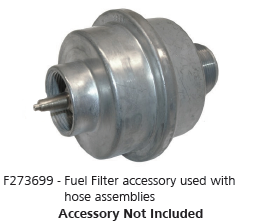
GENERAL INFORMATION:• When the heater is cold or at room temperature, it willtake a few minutes for the burner(s) tile to turn brightorange. This is normal and the heater is working properly.If burner(s) tile is visibly flaming, turn heater offand call a qualified service technician.• When the unit is lit, there should be about a quarterinch border around the tile that will not turn brightorange. This is normal.• When operating the heater at altitudes over 7,000FT. above sea level, the unit may not burn as brightas in lower altitudes. This is normal. At higheraltitudes, the heater may shut-off. If this happens,provide fresh air, wait 5 minutes and re-light. Due tolocal atmospheric conditions heater may not re-light.• Operating time will vary depending on the heater settingand the supply cylinder size. (One 1 lb. cylinder: 1.5to 6 hours. Two 1 lb. cylinders: 3 to 12 hours. Two 20lb. cylinders: 50 to 220 hours.) Heater may be operatedfrom quick disconnect, one or both tank swivel inlets.Due to the properties of LP gas, run times can be significantlyreduced when operating continuously at temperaturesbelow 20º F. Use of a 20lb tank is recommendedin these conditions.• When moving heater when lit or bumping heater settingit down, tip over switch may shut off heater. If thishappens, re-light.NOTE: THIS HEATER MAY BE OPERATED WITH (1) OR(2) DISPOSABLE 1 LB. PROPANE CYLINDERS OR WITHA REMOTE REFILLABLE CYLINDER(S) MAX. 20 LBSUSING (1) OR (2) F273701, F273702 OR F272702 HOSEASSEMBLIES WITH FUEL FILTERS (F273699)(Fig. A) ONEACH HOSE ASSEMBLY. HOSE NO. F273704 BUDDYSERIES HOSE, FUEL FILTER NOT REQUIRED. IT MAYALSO BE OPERATED WITH (1) F271802 HOSE ASSEMBLYCONNECTED TO A REGULATED (11” W.C.) PROPANESOURCE *FILTER NOT REQUIRED* OR (1) F271803 HOSEASSEMBLY WITH 11” REGULATOR WITH ACME NUT*FILTER NOT REQUIRED*.

NEVER LEAVE THE HEATER UNATTENDED WHILE BURNING!
LIGHTING / OPERATING INSTRUCTIONSFOR USE WITH DISPOSABLE 1 LB.PROPANE CYLINDERS:WARNING: Always inspect propane cylinder and heater propaneconnections for damage, dirt, and debris before attachingpropane cylinder. Do not use if head of cylinder is damaged,punctured or deteriorated.ALWAYS ATTACH OR DETACH CYLINDER OUTDOORS AWAYFROM FLAMES, OTHER IGNITION SOURCES, AND ONLY WHENHEATER IS COOL TO TOUCH. NEVER SMOKE WHEN ATTACHINGOR REMOVING PROPANE CYLINDER OR MAKING REMOTECONNECTIONS!• Use only LP-gas cylinders marked in accordance with theU.S. Dept. of Transportation (DOT).• Use only 16.4 oz. (1 lb.) disposable cylinders that matewith No. 600 valve connection.• Heater and attached cylinder(s) must be in an uprightposition during operation.• Make sure five-position Control Knob is in “OFF” position;see Figure 1.• Screw 1 lb. disposable LP-gas supply cylinder(s) clockwise(from bottom) into portable heater until hand tight.DO NOT use thread sealant on this connection.• Check cylinder(s) connection for leaks with soapy waterat the threaded connection under the domed plasticcover where the cylinder screws into the tank swivel.SEE WARNING!
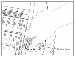

• Depress the Control Knob and turn counterclockwise tothe pilot position.• Hold Control Knob down in the pilot position for 30-40seconds.• While holding down the Control Knob, rotate clockwiseto the OFF position and immediately turn back to thepilot position, a spark will be generated at the pilot assemblyand the heater should light.
• If the heater does not light on the first attempt, repeatthe procedure.• Once the pilot has lit, hold the Control Knob down foran additional 30 seconds to heat the thermocouple. After30 seconds, release the Control Knob and the pilotshould remain lit.• If the pilot goes out repeat the lighting procedure.• After lighting pilot, release Control Knob. Control Knob shouldreturn to fully extended position. To operate heater slightlydepress knob and gently turn to lock in desired position.• Turn control knob to “LO” or “MD” position to lightheater. Leave on “LO” or “MD” position until firstburner tile has turned bright orange.• After first burner tile has turned bright orange, adjustheat output by turning Control Knob to desired position(“LO”, “MD” or “HI”) NOTE: Both tiles ignite only whenControl Knob is positioned on ‘HI’. (2) 1 LB. propanebottles are needed to use heater in (HI) position.
Warning: DO NOT OPERATE HEATER UNLESS CONTROL KNOB ISLOCKED IN A POSITION MARKED “HI”, “MD”, “LO” or“PILOT”. NEVER SET CONTROL KNOB BETWEEN LOCKEDPOSITIONS. POOR COMBUSTION AND HIGHER LEVELS OF
• To shut off heater, slightly push down and turn ControlKnob clockwise to “OFF” position.• CAUTION: After turning heater off, wire guard willremain hot. Allow to thoroughly cool before storing.• Do not operate, store or remove cylinder(s) near flammableitems or ignition sources.• LP-GAS CYLINDERS MUST BE DISCONNECTED FROMHEATER WHEN NOT IN USE!
NEVER LEAVE THE HEATER UNATTENDED WHILE BURNING!
LIGHTING / OPERATING INSTRUCTIONSFOR USE WITH HOSE(S) CONNECTED TOA REMOTE CYLINDER, MAXIMUM SIZE 20LBS:• WARNING: ANY HOSE CONNECTION TO A QUICKDISCONNECT FITTING ON HEATER MUST BEREGULATED TO 11” W.C. PRESSURE• Mr. Heater Hose No. F271802 which includes a quickdisconnect fitting and a 3/8” female flare fittingconnected to a regulated (11” W.C.) propane source.• Mr. Heater Hose No. F271803 which includes a quickdisconnect fitting and a 11” W.C. regulator.• DANGER! NEVER bring a refillable propane cylinderindoors. A fire or explosion can occur causing propertydamage, serious injury or death!• Inspect the hose before each use of the heater. If thereis excessive abrasion or wear, or the hose is cut, replaceprior to using the heater with one of the Mr. HeaterHose No’s. shown above.• The propane cylinder must include a listed overfillingprotection device as well as a collar to protect thecylinder valve.• Heater must be in an upright position during operation.• Make sure five-position control knob is in “OFF”position; see Figure 1, at left.• Mr. Heater strongly recommends using disposablefuel filter F273699, which connects to tank swivel onheater to trap any oil substances when connected to aremote cylinder that can make the heater inoperable.• Screw hose connector into tank swivel or fuel filteron heater or connect to quick disconnect and screwconnector on other end of hose into LP-gas supplycylinder valve. Tighten all hose connections. DO NOTuse thread sealant on any of these connections.• Open valve at LP-gas supply cylinder.• Check all hose connections for leaks with soapy waterat the threaded connection under the domed plasticcover where the hose connector screws into the tankswivel and/or fuel filter and at LP-gas supply cylinder.SEE WARNING!• Depress the control knob and turn counter-clockwise tothe pilot position.
• Hold control knob down in the pilot position for 1-5seconds.• While holding down the control knob, rotate clockwiseto the OFF position and immediately turn back to thepilot position, a spark will be generated at the pilotassembly and the heater should light.• If the heater does not light on the first attempt, repeatthe procedure.• Once the pilot has lit, hold the control knob down foran additional 30 seconds to heat the thermocouple.After 30 seconds, release the control knob and the pilotshould remain lit.• If the pilot goes out repeat the lighting procedure.• After lighting pilot, release knob. Knob should returnto fully extended position. To operate heater slightlydepress knob and gently turn to lock in desired position.• Turn control knob to “LO” or “MD” position to lightheater. Leave on “LO” or “MD” position until firstburner tile has turned bright orange.• After first burner tile has turned bright orange, adjustheat output by turning Control Knob to desired position(“LO”, “MD” or “HI” setting). (2) 1 LB. propanebottles are needed to use heater in (HI) position.
![]()
![]()
![]()
![]()
![]()
![]()
![]()
![]()
![]()
![]()
![]()
![]()
![]()
![]()
![]()
Warning:![]()
![]()
![]()
![]()
![]()
![]()
![]()
![]()
![]()
![]()
![]()
![]()
![]()
![]()
![]()
• To shut off heater, shut off propane at supply tank,allow heater to use-up propane in supply line untilheater shuts off, then slightly push down and turnControl Knob clockwise to “OFF” position.• CAUTION: After turning heater off, wire guard willremain hot. Allow to thoroughly cool before storing.• When not in use, the gas must be turned off at the LPgassupply cylinder. As stated before allow heater to useup propane in supply line until heater shuts off. Whenthe LP-gas supply cylinder is not disconnected fromthe heater, the heater and the cylinder must be storedoutdoors, in a well ventilated space, out of reach ofchildren, and must not be stored in a building, garageor any other enclosed area.• Indoor storage of the heater is permissible only if thecylinder is disconnected and removed from the heater.Cylinders must be stored outdoors out of the reach ofchildren and must not be stored in a building, garage orany other enclosed area.
NEVER LEAVE THE HEATER UNATTENDED WHILE BURNING!
MAINTENANCE:Always keep the heater area clear and free from combustiblematerials, gasoline and other flammable vapors and liquids.Keep the vent areas (slots in the bottom and the top at the frontof heater) clear at all times.Visually inspect the pilot flame and burner periodically duringuse. The pilot flame should be blue in color (not yellow) and willextend beyond the thermocouple. The flame will surround thethermocouple just below the tip, see Figure 2. A slight yellowflame may occur where the pilot flame and main burner flamemeet. The burner(s) should be bright orange (with a slight bluecolor around the border, a red-orange haze that is visible on theceramic tile is acceptable) and without a noticeable flame. Ablue flame that rolls out at the top of the ceramic tile indicatesan accumulation of dust, lint or spider webs inside the casingassembly and main burner assembly. If the pilot is yellow or theburner has a noticeable flame, cleaning may be required. Usethe following procedure to inspect the casing assembly and mainburner assembly.It is necessary to periodically check the burner(s) orifice andburner venturi tube to make sure they are clear of insects/nests orspider webs that may accumulate over time. A clogged tube canlead to a fire.


1. Allow heater to thoroughly cool before performing anymaintenance.2. Remove disposable 1 lb. cylinder(s) from heater or turnOFF gas supply at remote cylinder valve, and disconnecthose from heater.3. Remove wire guard from front of heater by gently bendingto remove from holes in front cover.4. Remove (4) screws securing back cover to heater. Liftup slightly to release (2) plastic hooks on top of backcover.5. Remove back cover.6. Remove (3) screws attaching lower baffle to exposeburner air openings.7. Inspect interior of casing assembly for accumulation ofdust, lint or spider webs. If necessary, clean interiorof casing assembly with a vacuum cleaner or apply airpressure (max. 30 psi). Do not damage any componentswithin casing assembly when you are cleaning.
8. Inspect and clean main burner orifice located at bottomof burner venturi tube, by using a vacuum or apply airpressure at orifice opening.9. Inspect and clean pilot (mounted to bracket) by using avacuum or apply air pressure through the holes in thepilot indicated by the arrows in Figure 2.WARNING: Never use needles, wires, or similar cylindricalobjects to clean the pilot to avoid damaging thecalibrated ruby that controls the gas flow.10. Apply air pressure (max. 30 psi) into ceramic tile ofburner(s) assembly and the venturi tube (with [2] airopenings) to remove dust, lint or spider webs.11. Reinstall lower baffle with (3) screws12. Slide back cover over (2) plastic hooks on top of heater.Make sure rear cover aligns with plastic side covers.Install (4) screws to hold in place.
TROUBLESHOOTING INFORMATION:If Spark electrode does not produce spark.CHECK• Spark electrode broken – replace.• Igniter wire may not be attached to spark electrode –attach.• Igniter wire damaged – replace.• Piezo igniter on control valve defective – replace controlvalve.If Spark electrode produces spark but pilot does not light.CHECK• No gas to heater – install disposable cylinder or connecthose and fuel filter then turn on valve at remotecylinder.• “PILOT” position not properly aligned – turn gascontrol knob to “PILOT” position and depress.• Pilot is blocked from spider web or dirt – clean pilot, seeMAINTENANCE.If Pilot flame does not stay lit when knob is released.CHECK• Control knob in “PILOT” position not completelydepressed or held in long enough to purge air fromlines.• Pilot flame not surrounding thermocouple – clean pilot,see MAINTENANCE.• Pilot Assembly defective – replace.• Tip switch wires disconnected – connect.If Main burner(s) does not ignite.CHECK• Main burner(s) orifice is blocked – clean burner(s), seeMAINTENANCE.If Heater keeps shutting “OFF” during normal operation.CHECK• Pilot is blocked – clean pilot, see MAINTENANCE.• Provide minimum fresh air opening of 18 square inches(example 4 1/4” x 4 1/4” opening).• Tip over switch activated from bumping heater. Relight
NEVER LEAVE THE HEATER UNATTENDED WHILE BURNING!
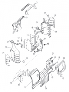
PARTS LIST:SEE BACK PAGE FOR PARTS ORDERING INFORMATION
REF. # ITEM # DESCRIPTION1……………..78402……………..HANDLE, ASSEMBLY3……………..78442……………..BACK, COVER9……………..78410……………..DOOR LEFT SIDE COVER10……………78411……………..LEFT, SIDE, COVER11……………78412……………..(2) REGULATORS, MH18B12……………78413……………..TIE, WRAPS13……………78414……………..BRACKET, LEFT, SIDE, REG,14……………78415……………..LEFT, SIDE, GAS, SUPPLY, LINE15……………78518……………..FRAME, ASSEMBLY16……………78417……………..BRACKET, RIGHT, SIDE, REG,17……………78418……………..KNOB, CONTROL18……………78419……………..DOOR, RIGHT, SIDE, COVER19……………78420……………..RIGHT, SIDE, COVER20……………78421……………..VALVE, CONTROL, ASSEMBLY21……………78422……………..PILOT, ASSEMBLY22……………78423……………..SHIELD, HEAT, BACK23……………78424……………..SHIELD, HEAT, FRONT24……………78516……………..COVER, FRONT25……………78519……………..GUARD, WIRE, FACE26……………78427……………..BRACKET, BOTTOM, PLENUM,ASSEMBLY27……………78428……………..PILOT, BRACKET28……………78515……………..REFLECTOR29……………78526……………..TILE30……………78525……………..TILE, GASKET (NOT SHOWN)31……………78517……………..PLENUM, BODY (2 REQUIRED)32……………78432……………..BRACKET, TOP, PLENUM,ASSEMBLY33…………… 78527……………..BURNER ORIFICE (NOT SHOWN)34…………… 78403……………..TIP-SWITCH
ACCESSORIES
ITEM# DESCRIPTION
F271802 – 12 ft. PROPANE HOSE ASSEMBLY w/quick disconnect fittings and 3/8” female flare fittingF271803 – 12 ft. PROPANE HOSE ASSEMBLY w/quick disconnect fittings and 11” W.C. regulator w/Acme nut.The following hose assemblies can also be used (with fuel filter F273699).
F273699 – Fuel Filter (Replace Annually)F273701 – 5 ft. PROPANE HOSE ASSEMBLY (Swivel 1”- 20 Male Throwaway Cyl. Thd. X P.O.L. w/Handwheel)F273702 – 12 ft. PROPANE HOSE ASSEMBLY (Swivel 1”- 20 Male Throwaway Cyl. Thd. X P.O.L. w/Handwheel)F272702 – 12 ft. PROPANE HOSE ASSEMBLY (Swivel 1”- 20 Male Throwaway Cyl. Thd. X P.O.L. w/Handwheel)F273704 – 10 ft. BUDDY-SERIES HOSE ASSEMBLY (Fuel filter not required)
NEVER LEAVE THE HEATER UNATTENDED WHILE BURNING!
Mr. Heater • Big Buddy • Model # MH18B

Mr.Heater Portable Propane Heater MH18B User Manual – Mr.Heater Portable Propane Heater MH18B User Manual –
[xyz-ips snippet=”download-snippet”]

