Club Therapy Steambath Generator Systems User Manual
READ ME FIRST!
IMPORTANT NOTE: As you follow these instructions, you will notice warning and caution symbols. This blocked information is important for the safe and efficient installation and operation of this generator. These are types of potential hazards that may occur during this installation and operation:
![]() states a hazard may cause serious injury or death if precautions are not followed.
states a hazard may cause serious injury or death if precautions are not followed.
![]() signals a situation where minor injury or product damage may occur if you do not follow instructions.
signals a situation where minor injury or product damage may occur if you do not follow instructions.
![]() is used to address practices not related to physical injury.
is used to address practices not related to physical injury.
IMPORTANT NOTE: This highlights information that is especially relevant to a problemfree installation.
All information in these instructions is based on the latest product information available at the time of publication. Sussman-Automatic Corporation reserves the right to make changes at any time without notice. More current instructions may be available at www.mrsteam.com
When installing and using this electrical equipment, basic safety precautions should always be followed, including the following:
IMPORTANT SAFETY INSTRUCTIONS
- READ AND FOLLOW ALL INSTRUCTIONS
 Do not permit children under the age of 16 to use this steambath.
- To reduce the risk of injury:
A. The wet surfaces of steam enclosures may be slippery. Use care when entering or leaving.B. The steam head is hot. Do not touch the steam head and avoid the steam near the steam head.C. Prolonged use of the steam system can raise excessively the internal human body temperature and impair the body’s ability to regulate its internal temperature (hyperthermia). Limit your use of steam to 10-15 minutes until you are certain of your body’s reaction.D. Excessive temperatures have a high potential for causing fetal damage during the early months of pregnancy. Pregnancy or possibly pregnant women should consult a physician regarding correct exposure.E. Obese persons and persons with a history of heart disease, low or high blood pressure, circulatory system problems, or diabetes should consult a physician before using a steambath.F. Persons using medication should consult a physician before using a steambath since some medication may induce drowsiness while other medications may affect heart rate, blood pressure and circulation.SAVE THESE INSTRUCTIONS
mr.steamSTEAM ROOM BENEFITSSteam bathing is a communal activity. Enjoy steam together with friends. Relax, knowing that steam may be a natural detox. Here are some possible benefits of steam bathing:– Cleanses, nourishes, and hydrates skin– Boosts metabolism– Provides relief for respiratory ailments such as colds, flu, allergies, and asthma– Reduces stress and promotes restful sleepFollow your steambath with a refreshing shower.If you would like your own personal steam bath at home contact us at mrsteam.com
![]() WARNING
WARNING
REDUCE THE RISK OF OVERHEATING AND SCALDING
- Exit immediately if uncomfortable, dizzy or sleepy. Staying too long in a heated area is capable of causing overheating.
- Children under the age of 16 should not use the steam bath.
- Check with a doctor before use if pregnant, diabetic, in poor health or under medical care.
- Breathing heated air in conjunction with consumption of alcohol, drugs or medication is capable of causing unconsciousness.
- Do not contact steam head or steam at the steam head.
REDUCE THE RISK OF SLIPPING AND FALL INJURY
Use care when entering or exiting the steam room, floor may be slippery.
Note: For additional safety considerations see owner’s manual.
HYPERTHERMIA
occurs when the internal temperature of the body reaches a level several degrees above the normal body temperature of 98.6° F. The symptoms of hyperthermia include an increase in the internal temperature of the body, dizziness, lethargy, drowsiness, and fainting. The effects of hyperthermia include:
a) Failure to perceive heat;b) Failure to recognize the need to exit the steambath;c) Unawareness of impending risk;d) Fetal damage in pregnant women;e) Physical inability to exit the steambath andf) Unconsciousness.
![]() The use of alcohol, drugs, or medication can greatly increase the risk of hyperthermia.
The use of alcohol, drugs, or medication can greatly increase the risk of hyperthermia.
![]() A warning placard has been provided in the Information envelope. This placard is an essential part of providing a safe environment for steam room users. This placard must be mounted to the wall of the shower or steam enclosure, at a point visible to all users. Failure to mount this placard may result in serious injury or death
A warning placard has been provided in the Information envelope. This placard is an essential part of providing a safe environment for steam room users. This placard must be mounted to the wall of the shower or steam enclosure, at a point visible to all users. Failure to mount this placard may result in serious injury or death
Select Your Club Therapy Model
Materials of construction, room size and special design features such as large glass areas, all affect the steam generator model selection.
- Measure length, width & height in feet of the steam/shower or tub/showerMultiply the Length ____ x Width____ x Height _____ =: ROOM VOLUME
- Construction Materials:For natural stones: natural marble, stone, shale, glass block or concrete: Add 110%For ceramic or porcelain tile on cement board or mortar bed: Add 40%
- Ceiling Height: For each foot above 8 feet (max. of 10 feet): Add 15%
- Add all figures above to obtain the Total Room Volume required: TOTAL ADJUSTED
Compare your TOTAL ADJUSTED ROOM VOLUME to the Specification Chart below and select the appropriate model.Visit www.mrsteam.com to size your generator automatically.
![]() In considering a purchase of this steambath system, please note that if users are pregnant, have a coronary condition, are in poor health, are being treated for any other medical condition, or are using medication or drugs, MrSteam recommends that you obtain the approval of their physician before use. For information about this product and safety issues, please call us at 1-800-76-STEAM or log onto www.mrsteam.com
In considering a purchase of this steambath system, please note that if users are pregnant, have a coronary condition, are in poor health, are being treated for any other medical condition, or are using medication or drugs, MrSteam recommends that you obtain the approval of their physician before use. For information about this product and safety issues, please call us at 1-800-76-STEAM or log onto www.mrsteam.com
IMPORTANT NOTES:
- The guidelines for selecting the steambath generator is a recommendation only. Because of variables in construction, these sizing instructions and specifications should be considered as guidelines only. MrSteam will review the model selected provided we receive complete information, including working drawings, specifications, and pertinent electrical and construction details. Otherwise, the manufacturer disclaims responsibility for the sizing of a model selected.
- For steam rooms constructed of acrylic or synthetic materials, select next lower-rated CT model.
- The total adjusted room volume allows for up to 60 feet of insulated steam piping from the CT generator to the steam room. If the 60 feet piping is exceeded consult with factory. When locating the steam generator consideration of the control and external temperature probe must be taken into account. The maximum length for a control cable is 60 feet. The maximum length of the MSTS is 60 feet. MSTS connects to the steam generator and is required to be installed inside the steam room when the control is mounted outside the steam room.
Steam Generators Specification Chart
Model No.: KW: Amps (for 240v/1PH)†: Total Adj Room Vol.: Wire Size‡: Water Usage gallons ††: Dimensions*: Shipping Wt. (Ibs)**
CT6E: 6: 25: 150: 8: 0.80: 17″L x 18½”H x 77⁄8″D: 40CT9E: 9: 38: 360: 8: 1.2: 17″L x 18½”H x 77⁄8″D: 40CT12E: 12: 50: 575: 6: 1.6: 17″L x 18½”H x 77⁄8″D: 40CT15E: 15: 63: 675: 4: 2.0: 17″L x 18½”H x 77⁄8″D: 40
IMPORTANT NOTES:
- Add C1 suffix to Model No. for 240V/1Ph; Add B1 suffix to Model No. for 208V/1Ph.
- All CT MS Models are cUL us Listed and CE; approved.
![]() All CT Generators available in 240v/1PH, 208v/1PH and other voltages/phases.† Amps are for 240/1PH rated units.‡Wire size (AWG) based on minimum 90˚C rated THHN copper conductors. Refer to the National Electrical Code for other types of conductors.
All CT Generators available in 240v/1PH, 208v/1PH and other voltages/phases.† Amps are for 240/1PH rated units.‡Wire size (AWG) based on minimum 90˚C rated THHN copper conductors. Refer to the National Electrical Code for other types of conductors.
*Dimensions are for generator only, without AutoFlush® or plumbing features.**Shipping weight and pricing are for generator only, without control or steamhead.†† Water usage based on 20 minutes of operation.
Before Installing
Carefully inspect the CT steam generator and packaging for shipping damage. In the event of shipping damage, please contact the carrier for claim information. Our customer service department can assist you with any missing or damaged parts.
Read these instructions before installation or service. Although this CT steam generator has been fully qualified for shipment by MrSteam, the following must be reviewed for proper, safe and enjoyable steam bathing:
- Verify that the model and accessories specifications are correct for the incoming line voltage.
- Insure steambath generator has been correctly sized for the steambath room. Pay particular attention to room volume and construction. If any questions, please refer to MrSteam sizing and selection guide on page 2.
- Marble or glass walls or ceilings “enlarge” the room’s size requiring a generator larger than one based only on the room’s cubic foot (L x H x W) volume.
- The physical size of the unit, clearance for plumbing servicing, and its distance from the steam room must all be considered before final installation.
- Consider any controls and accessories before initiating installation. Read the Installation & Operation Manual of all controls and accessories available at www.mrsteam.com/products/technical downloads.html
Steam Room Guidelines
IMPORTANT NOTE: Owners/Operators should obtain a copy and familiarize themselves with the latest edition of the American College Sports Medicine Health/Fitness Facility Standards and Guidelines, or a similar resource and reference publication, and refer to those guidelines for the proper and safe operation of a spa facility including rooms.
- Steam room must be completely enclosed, with full walls, door, floor and ceiling.
- It is recommended that a gasketed door is used for steam containment.
- If tile-type or other smooth surfaced flooring is used provide suitable anti-skid strips or equivalent, to prevent a slipping hazard.
- Check the suitability of any materials with the manufacturer. Walls and ceilings must be constructed of water-resistant, non-corrosive surface, such as tile, marble, molded acrylic, or other non-porous material.
- The ceiling should be sloped to prevent dripping of condensate.
- Provide a floor drain.
- No heating, venting or air conditioning devices should be installed inside the steam room.
- Steam room tile construction information is available from the Tile Council of America, Inc. by purchasing the TCA Handbook for Ceramic Tile Installation.at (864) 646-8453 or www.tileusa.com.
- Windows that are part of the steam room should be doublepaned and tempered safety glass.
- Limit steam room ceiling height to 8 feet. Exceeding 8 feet may require a higher-rated steam generator.
![]() The warning placard is located in the documentation envelope. This placard is an essential part of providing a safe environment for steam room users. This placard must be mounted to the wall of the shower or steam enclosure, at a point visible to all users. Failure to mount this placard may result in serious injury or death. For a replacement placard contact MrSteam customer service at 1- 800-76-STEAM or [email protected]
The warning placard is located in the documentation envelope. This placard is an essential part of providing a safe environment for steam room users. This placard must be mounted to the wall of the shower or steam enclosure, at a point visible to all users. Failure to mount this placard may result in serious injury or death. For a replacement placard contact MrSteam customer service at 1- 800-76-STEAM or [email protected]
![]() Never use damaged equipment, doing so may result in an inoperative or hazardous installation.Discontinue use of the steam generator and control if the steam generator or control are damaged or otherwise not functioning properly. Doing so may result in an inoperative or hazardous installation ELECTRICAL SHOCK HAZARD. MrSteam steam generators are connected to 208V or 240V line voltage and contain live electrical components. All installation and service to be performed by qualified and licensed electricians and plumbers only. nstallation or service by unqualified persons or failure to use MrSteam parts may result in property damage or in a hazardous condition.
Never use damaged equipment, doing so may result in an inoperative or hazardous installation.Discontinue use of the steam generator and control if the steam generator or control are damaged or otherwise not functioning properly. Doing so may result in an inoperative or hazardous installation ELECTRICAL SHOCK HAZARD. MrSteam steam generators are connected to 208V or 240V line voltage and contain live electrical components. All installation and service to be performed by qualified and licensed electricians and plumbers only. nstallation or service by unqualified persons or failure to use MrSteam parts may result in property damage or in a hazardous condition.![]() Do Not alter or modify any MrSteam product.Doing so may result in an inoperable or hazardous installation and will void the warranty
Do Not alter or modify any MrSteam product.Doing so may result in an inoperable or hazardous installation and will void the warranty
![]() If acrylic, fiberglass or other non-heat resistant materials are used as part of the steam room enclosure. Consult with the material manufacture and see pg. 7, “Installing the AromaSteam Steamhead” for additional details.IMPORTANT NOTES:This document contains important safety, operation and maintenance information. Leave this document with the club/spa management.Do not discard this document.The following general information should be used in conjunction with consultations with an architect, designer and contractor in determining factors necessary in providing a suitable and safe steam room.MrSteam CT steam generators are intended to be operated with MrSteam’s iTempo/Plus™, iSteam® and CT SteamStop® only, and are to be installed strictly in accordance with the specific instructions contained in this manual and as supplied in the manuals provided with the controls or accessories.
If acrylic, fiberglass or other non-heat resistant materials are used as part of the steam room enclosure. Consult with the material manufacture and see pg. 7, “Installing the AromaSteam Steamhead” for additional details.IMPORTANT NOTES:This document contains important safety, operation and maintenance information. Leave this document with the club/spa management.Do not discard this document.The following general information should be used in conjunction with consultations with an architect, designer and contractor in determining factors necessary in providing a suitable and safe steam room.MrSteam CT steam generators are intended to be operated with MrSteam’s iTempo/Plus™, iSteam® and CT SteamStop® only, and are to be installed strictly in accordance with the specific instructions contained in this manual and as supplied in the manuals provided with the controls or accessories.
Locating the Steam Generator Unit
IMPORTANT NOTE: The control cables should be run in dedicated 1″ conduit to facilitate installation and service Select a location as near as practical to the steam room.Typical locations include: closet, vanity cabinet, heated attic or basement.![]() The maximum length of the MSTS is 60 feet. MSTS connects to the steam generator and is required to be installed inside the steam room when the control is mounted outside the steam room.
The maximum length of the MSTS is 60 feet. MSTS connects to the steam generator and is required to be installed inside the steam room when the control is mounted outside the steam room.![]() (Items 1-7)
(Items 1-7)
- DO NOT install steambath generator or plumbing lines in unheated attic or any locations where water could freeze.
- DO NOT install steambath generator inside steam room.
- DO NOT install steambath generator outdoors or wherever environmental conditions may affect the safety and/or performance of the generator.
- DO NOT install steambath generator near flammable or corrosive materials or chemicals such as gasoline, paint thinners, or the like. Installation in areas having high concentrations of chlorine (such as pool equipment room) must be avoided.
- Install steambath generator on a solid and level surface. Provide supports under steam generator when wall mounting. Keyhole slots are provided for wall mounting.Insure the steam generator is properly secured and level when mounting with keyhole slots.
- Install steambath generator in an upright position only.
- Burn Hazard. Steam piping, safety valve, drain valve, plumbing and steamheads become hot during operation and remain hot after shutdown for a period of time. Provide appropriate protection, including insulating plumbing lines.Avoid plumbing runs and steamhead locations that can come in contact with bathers.IMPORTANT NOTE: (Items 8-11)
- Install anti-water hammer device as necessary.
- Provide a minimum of 12 inches at both ends and top of the steam generator or as required for servicing.
- Provide unions as required to facilitate installation and disconnection of piping.
- The controls should be placed in a location only accessible by the facility’s staff.The CT SteamStop® and remote sensor are required to be installed inside the steamroom. MrSteam Generators and controls are CE and UL listed. The CT series of steam generators are for commercial use only.
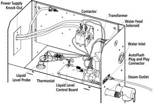
Typical MrSteam® Installation
![]() FOR ILLUSTRATIVE PURPOSES ONLYSome components may be omitted or altered for clarity. Do not use for wiring, repair or other purposes not related to component identification.
FOR ILLUSTRATIVE PURPOSES ONLYSome components may be omitted or altered for clarity. Do not use for wiring, repair or other purposes not related to component identification.

Installation
PlumbingAll plumbing shall be performed by a qualified licensed plumber and in accordance with applicable National and local codes.
- Use unions on all pipe connections.
- Use only brass piping or rigid copper tubing as permitted by codes.
- Do not use black, galvanized, PVC, or PEX pipe.
Water Supply ( 3⁄8″NP T )
- Connect to cold water line.
- Provide a shut off valve in the water supply line upstream of the steambath generator.
- Do not overheat inlet solenoid valve with solder connections.Overheating will damage parts.
- Flush inlet water line thoroughly before making connection to unit.
- Strainer recommended upstream of feed water connection.
- For best performance water pressure should be 15 to 20 psig.Reduce pressure as required.
- Provide anti-water hammer device as required.
- Install an approved backflow preventer as required by local codes.
Drain (1″ NP T )The drain from the generator should not share an undersink trap, unless the generator is mounted higher than the sink.A drain valve is provided to facilitate servicing. Provide a drain line connection from steambath generator drain valve according to National and local Codes.Check local plumbing code for receptor, trap and vent requirements. Do not connect Drain line and SafetyValve line together. Unit drains by gravity.Do NOT connect the drain valve to the steam piping.Safety Valve ( 3⁄4″NP T )Where permitted by local codes, provide an outlet plumbing connection for safety valve.To insure proper and automatic safety valve operation: DO NOT connect a shut off valve or a plug at safety valve outlet. DO NOT connect a shut off valve or any construction in steam supply piping.Condensation PanMrSteam strongly recommends the use of a condensation pan in the unlikely event of a plumbing leak. Check local plumbing codes for receptor, trap and vent requirements. Condensation pans drain by gravity. The condensation pan is equipped with an integral 3 ⁄4″ fitting. for additional condensation pan installation information.
AromaSteamIf the optional AromaSteam Electronic Oil Delivery System (PN: MS AROMA) is to be installed, a 90 degree T plumbing fitting must be installed at a designated location on the steam outlet line.See the MrSteam Aroma-Steam Operation and Instruction Manual for installation information before the steam piping is installed at www.mrsteam.com technical downloads.
Steam Piping ( 1⁄2″NP T )
- Do not install any valve in steam piping. Flow of steam must be unobstructed.
- Use 1 ⁄2 inch brass pipe or copper tubing from unit to steam head as permitted by codes.
- Insulate steam piping with fiberglass pipe insulation or similar insulation rated 212° F or higher.
- Pitch steam piping 1 ⁄4″per foot towards steam head or steam generator to avoid valleys and trapping of condensate.

![]() Failure to pitch the steam piping as required for condensate to drain, may cause condensate to block the flow of steam. Blocking the steam flow may cause steam pressure to discharge boiling water through the steamhead, resulting in a scalding hazard. Blocking the flow of steam may cause steam to discharge through the safety valve, resulting in a scalding hazard.
Failure to pitch the steam piping as required for condensate to drain, may cause condensate to block the flow of steam. Blocking the steam flow may cause steam pressure to discharge boiling water through the steamhead, resulting in a scalding hazard. Blocking the flow of steam may cause steam to discharge through the safety valve, resulting in a scalding hazard.![]() A 1.5″ hole in the steam room is required to mount the steamhead.Water Quality InformationFor optimum results, the water supply should be tested priorto installation. If the mineral content exceeds the following recommended limits, various external treatment processes are recommended to correct the problem.
A 1.5″ hole in the steam room is required to mount the steamhead.Water Quality InformationFor optimum results, the water supply should be tested priorto installation. If the mineral content exceeds the following recommended limits, various external treatment processes are recommended to correct the problem.![]() An analysis of the on-site water must be made by a recognized and reliable water treatment company to ascertain the existing condition and treatment required. Poor water quality can affect efficiency or result in steam generator damage. Water contains impurities in solution and suspension. These impurities concentrate in the generator. The concentration of these impurities increases as more feedwater is introduced into the generator and steam is produced. If the suspended solids are allowed to concentrate beyond certain limits, a deposit or “scale” will form on the generator internal surfaces. This deposit can interfere with the proper generator operation and cause generator failure. The concentration of these impurities is generally controlled by the water quality and by periodic draining of the generator.RECOMMENDED FEEDWATER QUALITYHardness, ppm 8 – 85 (~0.5 – 5 gpg)P-Alkalinity, ppm 85 – 410 (~5 – 24 gpg)T. Alkalinity, ppm 200 – 500 (~7 – 0 gpg) pH (strength of alkalinity) 8.0 – 11.4The CT AutoFlush System feature automatically drains the CT generator following each use. A time delay allows the water to cool down (about two hours) before it drains by gravity for a safe and gentle operation.
An analysis of the on-site water must be made by a recognized and reliable water treatment company to ascertain the existing condition and treatment required. Poor water quality can affect efficiency or result in steam generator damage. Water contains impurities in solution and suspension. These impurities concentrate in the generator. The concentration of these impurities increases as more feedwater is introduced into the generator and steam is produced. If the suspended solids are allowed to concentrate beyond certain limits, a deposit or “scale” will form on the generator internal surfaces. This deposit can interfere with the proper generator operation and cause generator failure. The concentration of these impurities is generally controlled by the water quality and by periodic draining of the generator.RECOMMENDED FEEDWATER QUALITYHardness, ppm 8 – 85 (~0.5 – 5 gpg)P-Alkalinity, ppm 85 – 410 (~5 – 24 gpg)T. Alkalinity, ppm 200 – 500 (~7 – 0 gpg) pH (strength of alkalinity) 8.0 – 11.4The CT AutoFlush System feature automatically drains the CT generator following each use. A time delay allows the water to cool down (about two hours) before it drains by gravity for a safe and gentle operation.
![]() A 1 1⁄2″ clearance hole around the steam pipe is needed to mount the steamhead.
A 1 1⁄2″ clearance hole around the steam pipe is needed to mount the steamhead.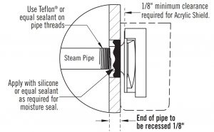
STEP 1Locate steam head 6-12 inches above floor, except for:
- Tub/shower enclosures, install 6 inches above tub top edge.
- Consult with supplier of acrylic, fiberglass and other non-heat resistant enclosures for recommended steamhead location.
- Use Acrylic Shield MS 103412. See instructions provided with steam shield.
- To reduce noise do not locate the steamhead within 12″ from a wall.
STEP 2Install steamhead with the oil well facing up as shown.Hand tightening is sufficient when teflon or equal pipe thread sealing compound is used.STEP 3Secure a bronze drop ear fitting to a header and run a 1⁄2″ copper steam pipe from the steam generator to the drop ear fitting. Install a temporary nipple (6″ or longer) in the drop ear fitting to locate the steamhead after the wall is finished.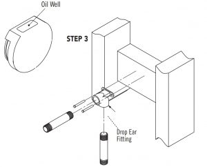 STEP 4After the wall has been finished, mark on the nipple where the surface of the wall is. Remove the nipple and measure the portion that was in the wall (the end to your mark). Subtract 1 ⁄8″ from that dimension and select a brass nipple of that length to finish the installation.
 STEP 5Wrap teflon tape around the threads of the new nipple and screwthe nipple into the steamhead. Do not use wrenches or tools which would damage the steamhead’s finish.Wrap teflon tape around the threads of the nipple and screw the nipple and steamhead assembly you just made into the drop ear fitting in the wall. The steamhead should be flush with the wall andthe well must be facing up.
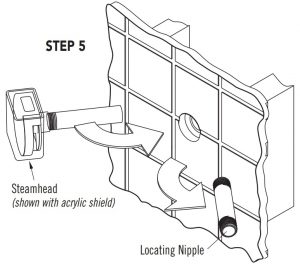
IMPORTANT NOTE:
- Do not disassemble steamhead. MrSteam’s steamhead is shipped fully assembled and requires no additional assembly.
- To preserve steam head finish, do not use wrenches or other tools to tighten. DO NOT use abrasive cleansers or chemicals.Use only water with mild soap and a non-abrasive sponge.
![]() Because the steam head and direct steam emissions are very hot, locate the steam head where incidental contact by bather with the steam head or direct steam emission cannot occur.
Because the steam head and direct steam emissions are very hot, locate the steam head where incidental contact by bather with the steam head or direct steam emission cannot occur.
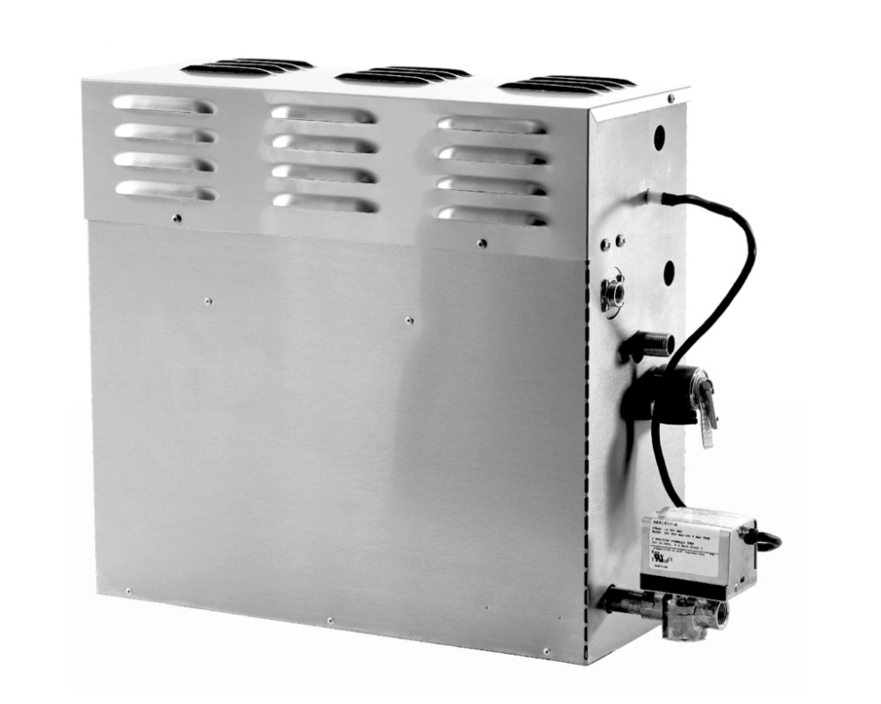
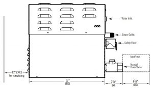
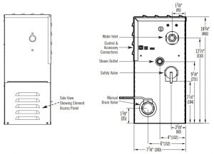
Generator Dimensions
IMPORTANT NOTES:
- Provide a minimum of 12 inches at both ends and top of the steam generator or as required for servicing.Alternately, provide unions as required to facilitate installation and disconnection of the steam generator.
- The minimum clearance from combustible surfaces is zero all around.TO AVOID EQUIPMENT DAMAGE DO NOT CONNECT POWER SUPPLY DIRECTLY TO ELEMENTS !!!
![]()
- M=Optional AutoFlush
- All units in inches (MM)
WATER INLET: 3/8” NPTSTEAM OUTLET: 1/2” NPTSAFETY VALVE: 3/4” NPTMANUAL DRAIN VALVE: 1” NPTAUTOFLUSH VALVE: 1” NPT
Electrical
All electrical wiring to be installed by a qualified licensed electrician in accordance with National Electrical Code and local electrical code.
Power Wiring- See “Field Power Wiring” Diagrams (below)
- Check power voltage. Use 240V rated unit when supply is greater than 208V. Use 208V rated unit for 208V power.
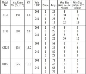
- Use minimum 90˚ C/300V rated insulated copper conductors only, sized in accordance with National Electrical Code and local electrical code for the current in Ampere Chart. If allowed by codes, NM cable may require a larger wire size than as listed on the chart.
- Connect suitably sized equipment grounding wire to ground terminal provided.
- Install a separate circuit breaker between supply and unit.Provide a power supply disconnect within sight of the steam generator or one that is capable of being locked in the open position.
- For single phase units, use two-wire supply source and equipment grounding wire. Neutral (white) wire is not required.
CHART
![]() Provide a power supply disconnect within sight of the steam generator or one that is capable of being locked in the open position as permitted by code.
Provide a power supply disconnect within sight of the steam generator or one that is capable of being locked in the open position as permitted by code.
Field Power Wiring
- TO AVOID EQUIPMENT DAMAGE DO NOT CONNECT POWER SUPPLY DIRECTLY TO ELEMENTS!!!
- L1, L2, Ground to be field wired
Models CT6E – CT9E (single phase wiring shown)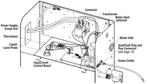 Models CT12E & 15E (single phase wiring shown)
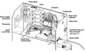
FOR ILLUSTRATIVE PURPOSES ONLYSome components may be omitted or altered for clarity. Do not use for wiring, repair or other purposes not related to component identification.
Single Phase Wiring Diagrams
MODEL CT6E & CT9E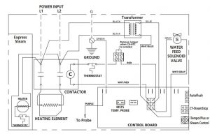 MODEL CT12E & 15E
Three Phase Wiring Diagrams
MODEL CT6E, CT9E CT12E & CT15E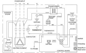
Initial Start-Up and Checkout
- Turn on control. Follow specific instructions provided with controls.
- Steam will begin to appear in approximately 5 minutes at the steam head. Steam will shut off when desired temperature is reached and will automatically resume when room temperature drops below set point.
- Steam will shut off automatically when control counts down to zero. To shut steam off manually, turn control OFF. To clear steam from enclosure area, turn shower on before opening door.
- If unit does not start and control does not turn ON(control display does not light up) then turn breaker off for 20 seconds and try again.
- Refer to specific instruction sheets for installation, operation and maintenance of optional equipment and Control.
Maintenance
MrSteam steambath generators require little maintenance. Other than draining, maintenance procedures are minimal. When AutoFlush is not installed the manual drain valve should be opened fully flushing out accumulated materials, salts and other particles which are natural by-products of boiling water, after each use.![]() Flush a minimum of two-three hours after the control has been turned off to insure that the water has cooled.
Flush a minimum of two-three hours after the control has been turned off to insure that the water has cooled.![]() Draining immediately after a steam cycle may expose PVC and other piping to high temperature water. Check local codes. The unit will refill automatically after 10 minutes. In areas of hard water, a MrSteam AutoFlush® system is recommended for generator longevity.
Draining immediately after a steam cycle may expose PVC and other piping to high temperature water. Check local codes. The unit will refill automatically after 10 minutes. In areas of hard water, a MrSteam AutoFlush® system is recommended for generator longevity.
Steam Generator Operation
MrSteam recommends beginning steam bathing at a low temperature setting to gauge comfort and safety levels. Set the duration at 10 minutes max. to gauge comfort and safety levels. This will allow the steam generator to heat up and begin producing.
Troubleshooting
Step 1: Check your main incoming power to the unit.Step 2: Verify the transformer is receiving 208/240 VAC.Step 3: Verify that you have 24VAC coming out of the transformer, WHT & WHT/BLU wires, into the board.Step 4: Verify that you have the green light on the PC board.Step 5: Push the white test button to run the generator on a 10 minute test cycle.Step 6: Verify that you have 24 VAC to the water feed solenoid, GRY & WHT/GRY wires (will fill when needed).Step 7: Temporarily short out the WLS (Purple wire) and GND (Green wire) terminals and verify the contactor engages.Step 8: When the red light is on, verify that you have 24 VAC, RED & WHT/RED wires, to the contactor.Step 9: Check to see that you have your main voltage on the load side of the contactor when it is engaged.Step 10: If all steps on the power path were verified, turn off power to the unit and pull the heating element via the left hand access panel for inspection.
![]() All electrical troubleshooting to be performed by a qualified licensed electrician.
All electrical troubleshooting to be performed by a qualified licensed electrician.
![]() FOR ILLUSTRATIVE PURPOSES ONLY.Some components may be omitted or altered for clarity. Do not use for wiring, repair or other purposes not related to component identification.
FOR ILLUSTRATIVE PURPOSES ONLY.Some components may be omitted or altered for clarity. Do not use for wiring, repair or other purposes not related to component identification.
Do not disassemble internal components, internal components contain no serviceable parts.
Liquid Level Control Board
EXPLANATION OF LED INDICATORS
GREEN: LED is ON when there is 208/240 Volt incoming power connected,24 Volt transformer secondary output and on-board 5 Volt DC control power are present.YELLOW: Water level indicator–LED is OFF when no water is detected (for more that 5 seconds). ON whenwater level is satisfactory. For units with AutoFlush, if more than five hours have elapsed sincelast usage and this LED is ON it is indicative of an AutoFlush or water level probe circuit malfunction.RED: Contractor relay indicator–LED is ON when relay is closed and sending 24 Volts to thecontractor coil. (This LED comes ON if the generator is ON.)FORCE ON: This button is for trouble shooting only and will operate if a control is connected or not.TEST BUTTON: Pressing the button again will shut the generator OFF.The test button will only allow the generator to operate for 10 minutes.
Liquid Level Control BoardPN 104288 (shown without wiring)
AutoFlush®
Box Contents
- AutoFlush Valve with Cord
- Installation instructions.
Operation
The AutoFlush System feature automatically drains the CT system following each use.A time delay allows the water to cool down (about two hours) before it drains by gravity for a safe and gentle operation. Unit drains by gravity.
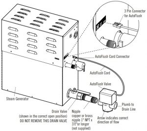
Installation Instructions
- Plumbing to be performed by a qualified plumber and shall be in accordance with applicable national and local codes. Unit drains by gravity. A drain line that is lower than the AutoFlush assembly must be available. The AutoFlush System valve outlet is 1″ NPT. Check plumbing code for receptor, trap and vent requirements.
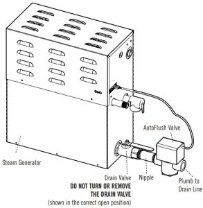
- Use copper or brass nipple 1″ NPT x 31⁄2″ or longer (not supplied) to connect AutoFlush valve to the Drain Valve, noting the direction of flow on the valve body. DO NOT REMOVE THE DRAIN VALVERemoval may cause equipment and property damage.If there is not enough room for the valve, an elbow and a short nipple (not provided) can be added.
- Open Drain Valve (handle must be aligned with brass nipple).
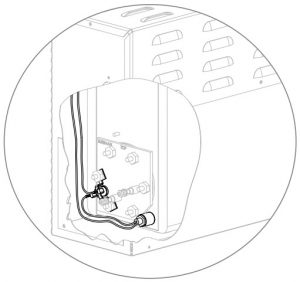
- Connect the AutoFlush System cord connector to the three pin connector as shown. Do not drain into a steam enclosure or any location where accidental contact with drain water may occur. In the event of a power failure the AutoFlush System valve will open and may discharge boiling water.
Sweat Fittings
When using sweat fittings use only tin base solder with a melting point below 600 degrees F. Do not overheat. Ends of water supply tubing must be thoroughly clean for a minimum distance of 1″ from ends. Do not remove valve cover.
![]() PROVIDE DRAIN PLUMBING ACCORDING TO LOCAL CODES. PLUMB AS REQUIRED FOR AUTOFLUSH SYSTEM.
PROVIDE DRAIN PLUMBING ACCORDING TO LOCAL CODES. PLUMB AS REQUIRED FOR AUTOFLUSH SYSTEM.
To Check Operation
- Turn on MrSteam and allow tank to fill with water.
- Turn off MrSteam control. Water should stay in tank.
- Turn off power at the panel box. Water should discharge from tank.
- Turn on power at panel box.
- Repeat
Condensation Pan
 MrSteam provides a condensation pan in the unlikely event of a plumbing leak.Locate the condensation pan on a solid level surface and place the steam generator inside the condensation pan.Insure the steam generator is level (see page 4 for locating the steam generator).All plumbing shall be performed by a qualified licensed plumber and in accordance with applicable national and local codes. Check local plumbing code for receptor, trap and vent requirements.Condensation pans drain by gravity. The condensation pan is equipped with an integral 3 ⁄4″ NPT fitting.
Express Steam® (Factory installed)
All CT models have Express Steam standard.Express Steam is equipped with a low power heating element and thermostat to keep the water in the tank warm enough to bring up steam quicker. All Express Steam components and wiring are installed at the factory. No additional wiring or plumbing is required by installers.
![]() FOR ILLUSTRATIVE PURPOSES ONLYSome components may be omitted or altered for clarity. Do not use for wiring, repair or other purposes not related to component identification.
FOR ILLUSTRATIVE PURPOSES ONLYSome components may be omitted or altered for clarity. Do not use for wiring, repair or other purposes not related to component identification.
Replacement Parts List
Part No.: Description: Product99178CT: Drain Valve :All models99297: Safety Valve 15PSI :All models100479-2: Water Feed Solenoid Valve w/filter :All models100477-3: Transformer 24VAC :All models104288: Liquid Level Control Board :All models103990-60: Cable for iTempo/Plus Control (60 ft.) :iTempo/Plus onlyMSTS-60: Remote Temperature Probe :iTempo/Plus only100476-2: Contactor 50A 2-pole :CT6E & CT9E, Single phase99012: Contactor 50A 3-pole :All 3-Phase models103453: Contactor 50A 4-pole: CT12E100471-2: Probe Assembly :All models99096MS: Heating Element Gasket :All models103412: Acrylic Shield :All Models99314: Power Fuse 60A 250V :CT12E, Single phase29061BMS: Heating Element 6 KW 208V :CT6E29061CMS: Heating Element 6 KW 240V :CT6E29091BMS: Heating Element 9 KW 208V :CT9E29091CMS: Heating Element 9 KW 240V :CT9E29121BMS: Heating Element 12 KW 208V :CT12E29121CMS: Heating Element 12 KW 240V :CT12E29151BMS: Heating Element 15 KW 208V :CT15E29151CMS: Heating Element 15 KW 240V :CT15E103978-60: Cable for CT-SteamStop (60 ft.) :All models104016: Thermostat :All models104015: Express Steam Thermostat :All models104019: Heating element for Express Steam: All models104117-30: Cable for iSteam (30 ft.): iSteam Only104117-60: Cable for iSteam (60 ft.): iSteam Only
Models CT6E & CT9E

![]() FOR ILLUSTRATIVE PURPOSES ONLY.Some components may be omitted or altered for clarity.Do not use for wiring, repair or other purposes not related to component identification.
FOR ILLUSTRATIVE PURPOSES ONLY.Some components may be omitted or altered for clarity.Do not use for wiring, repair or other purposes not related to component identification.
Models CT12E & 15E shown with cover removed

![]() FOR ILLUSTRATIVE PURPOSES ONLY.Some components may be omitted or altered for clarity. Do not use for wiring, repair or other purposes not related to component identification.
FOR ILLUSTRATIVE PURPOSES ONLY.Some components may be omitted or altered for clarity. Do not use for wiring, repair or other purposes not related to component identification.
Control Installation
Refer to Control Manual for specific installation requirements
Before InstallingTurn power to the steam generator OFF before connecting the control to the generator. Failure to turn the power off will result in an inoperable control.![]() To avoid unintentional steambath operation, do not locate the control where other controls, accessories, shower heads, valves, body sprays or similar within the shower could cause confusion or interferewith the MrSteam control’s intended use and function.
To avoid unintentional steambath operation, do not locate the control where other controls, accessories, shower heads, valves, body sprays or similar within the shower could cause confusion or interferewith the MrSteam control’s intended use and function.
![]() Do not use any iSteam®, iTempo/Plus™, iTempo™, HomeWizard™ or iGenie® controls without readingand understanding its own manual and the MrSteam steamgenerator Installation and Operation Manual. Failure to readand understand these instructions may result in an inoperative or hazardous installation.
Do not use any iSteam®, iTempo/Plus™, iTempo™, HomeWizard™ or iGenie® controls without readingand understanding its own manual and the MrSteam steamgenerator Installation and Operation Manual. Failure to readand understand these instructions may result in an inoperative or hazardous installation.
![]() The warning placard located in the documentation envelope must be read and permanently affixed in a conspicuous location near the steam room. Failure to read and affix this warning placard in a conspicuous location may result in serious injury or death.
The warning placard located in the documentation envelope must be read and permanently affixed in a conspicuous location near the steam room. Failure to read and affix this warning placard in a conspicuous location may result in serious injury or death.
Install the iSteam, iTempo or iTempo/Plus controls according to installation instructions. Failure to install according to instructions will result in an inoperative control or hazardous overheating or inadequate heating of the steam room.If an iSteam, iTempo or iTempo/Plus control is installed outside the steam room a Remote Temperature Probe (PN MSTS) must be installed inside the steam room per installation instructions supplied with the Remote Temperature Probe. Failure to install according to instructions will result in an inoperative control and overheating of the steam room.
![]() Do not route iSteam, iTempo/Plus, iTempo, HomeWizard or iGenie control wiring inside conduit together with power lines or close to hot water or steam piping. Doing so may result in an inoperative or hazardous installation.
Do not route iSteam, iTempo/Plus, iTempo, HomeWizard or iGenie control wiring inside conduit together with power lines or close to hot water or steam piping. Doing so may result in an inoperative or hazardous installation.![]() Do Not alter or modify any MrSteam product. Doing so may result in an inoperable or hazardous installation and will void the warranty
Do Not alter or modify any MrSteam product. Doing so may result in an inoperable or hazardous installation and will void the warranty
IMPORTANT NOTES:
- Turn power to the steam generator OFF before connecting the control to the generator. Failure to turn the power off will result in an inoperable control.
- Do not operate iSteam, iTempo/Plus, iTempo, HomeWizard or iGenie controls with other than a MrSteam iSteam or iTempo compatible steam generator. MrSteam steam generators with serial numbers lower than 900000, or any other brand of steam generator are not to be operated with iTempo controls.Doing so may result in an inoperative or hazardous installation. If iSteam is used with a generator having serial number less than 1174000, contact MrSteam technical support for an upgraded PC board.
- This document contains important safety, operation and maintenance information. Leave this document with management. Do not discard this document.
- Discontinue use of the steam generator or control if the steam generator is damaged or otherwise not functioning properly. Operating a damaged steam generator may result in an inoperative or hazardous installation
Control Rough In
Refer to Installation Instructions for the specific controlIMPORTANT NOTE: The control cables should be run in dedicated 1″ conduit to facilitate installation and service.
- Determine the desired installation location of the control. The iSteam®, iTempo™ and iTempo/Plus™ controls are designed to be installed inside or outside the steam room as a matter of personal preference. If the control is installed inside the steam room the control must be located:
- 4 -5 feet above the floor near the bather seating area
- The control features an integral temperature sensor.Locate the control in a location representative of the desired steambathing temperatures.Do not locate the control above or near the steam head or direct steam emissions.
- on a vertical wallThe control cable length is 30 feet. Insure that the control and/or steam generator are located accordingly. An optional 60 foot cable is available, PN 103990-60 for iTempo and PN 104117-60 for iSteam. Contact a MrSteam technical service representative if a 60 foot cable is required.IMPORTANT NOTE: If the control is installed outside thesteamroom a Remote Temperature Probe Part Number MSTS must be installed inside the steam room, depending on the control. Insure MrSteam steam generator is iSteam or iTempo compatible and has a serial number 900000 or higher. If iSteam is used with a generator having serial number less than 1174000, contact MrSteam technical support for an upgraded PC board. See instructions for the MSTS Temperature Probe (located in the Control Installation Manual related to your specific control package) before rough-in or installation of control.
CT SteamStop®
On/Off Switch for iTempo/Plus®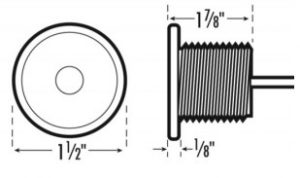
Dimensional InformationBox Contents:
- CT SteamStop Control
- Owner’s Manual
- 60’ CT SteamStop Cable
IMPORTANT NOTE: The control cables should be run in dedicated 1″ conduit to facilitate installation and service.Installing the CT SteamStop ControlThe CT SteamStop has a 60 foot cable with a Plug & Play connector at both ends. (Diagram 1) The CT SteamStop must be installed inside the steamroom.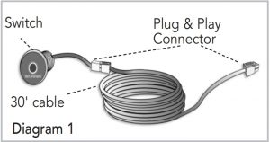 Step 1: Diagram 2Drill a 7⁄8 inch diameter hole in a preferred wall location. Do not oversize or undersize the hole.
 Step 2: Diagram 3Route the cable from the wall to the steam generator. Be careful not to strain, pinch or otherwise damage the control cable.
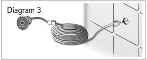 Step 3: Diagram 4Remove and discard the peel-off paper from the switch housing to expose the adhesive as shown in Diagram 4.IMPORTANT NOTE: Use care not to apply silicone to the adhesive gasket.Step 4: Diagram 5Apply silicone (provided with the iTempo/Plus control) to the hole in the wall as required to create a moisture seal. Apply silicone to the back of the switch as required to seal grout lines or as required for additional adhesion.
 Step 5: Push cable and switch housing into the hole firmly.Step 6: Diagram 6Firmly connect the Plug & Plac connector to the steam generator connector labeled CT SteamStop.
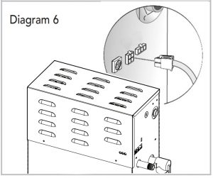
![]() The connector is keyed and will only connect in one orientation with the tab facing up.
The connector is keyed and will only connect in one orientation with the tab facing up.
Using the CT SteamStop® Control
The CT SteamStop control should be installed in the steam room for the user to start and stop the steam bath![]() If an error code is detected by the system the LED indicator will flash. Refer to the iTempo/Plus or iSteam display for error code or call a MrSteam’s service technician.
If an error code is detected by the system the LED indicator will flash. Refer to the iTempo/Plus or iSteam display for error code or call a MrSteam’s service technician.![]() For Illustrative Purposes Only. Drawings Not to Scale
For Illustrative Purposes Only. Drawings Not to Scale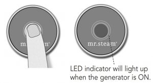
Care Tips for all Controls and Steamheads
- Use only mild soap and water on a soft cloth to clean the control and steamhead.
- Do not use abrasive cleansers.
- If the decorative cover is damaged on the iTempo/Plus call MrSteam technical service for replacement parts.
![]() Replacement of the decorative covers requires removal and reinstallation of the control from the mounting surfaces.
Replacement of the decorative covers requires removal and reinstallation of the control from the mounting surfaces.
Warranty Info:
Warranty: To view or download the MrSteam Steam Generator Warranty and register your product go to: blog.mrsteam.com/wr
Club Therapy Steambath Generator Systems User Manual [Models: CT6E, CT9E, CT12E, CT15E] – Club Therapy Steambath Generator Systems User Manual [Models: CT6E, CT9E, CT12E, CT15E] –
[xyz-ips snippet=”download-snippet”]