General Monitors S5000 Gas Monitor User Manual
WARNING!
Read this manual carefully before using or maintaining the device. The device will perform as designed only if it is used and maintained in accordance with the manufacturer’s instructions. Otherwise, it could fail to perform as designed, and persons who rely on this device could sustain serious injury or death.
The warranties made by MSA with respect to the product are voided if the product is not installed and used in accordance with the instructions in this manual. Please protect yourself and your employees by following the instructions. Please read and observe the WARNINGS and CAUTIONS inside. For additional information relative to use or repair, call 1- 800-MSA-2222 during regular working hours. For countries of Russian Federation, Republic of Kazakhstan and Republic of Belarus, the gas detector will be delivered with a passport document that includes valid approval information. On the CD with manual instruction attached to the gas detector the user will find the documents “Type Description” and “Test Method” – appendixes to Pattern Approval Certificate of Measuring instrument, valid in the countries of use.MSA is a registered trademark of MSA Technology, LLC in the US, Europe and other Countries. For all other trademarks visit https://us.msasafety.com/Trademarks.This product incorporates Bluetooth® wireless technology. The Bluetooth word mark and logos are registered trademarks owned by Bluetooth SIG, Inc., and any use of such marks by MSA is under license. Other trademarks and trade names are those of their respective owners. This device complies with part 15 of the FCC Rules. Operation is subject to the following two conditions: (1) This device may not cause harmful interference, and (2) this device must accept any interference received, including interference that may cause undesired operation. You are cautioned that changes or modifications not expressly approved by the party responsible for compliance could void the user’s authority to operate the equipment.This device complies with RSS-210 of the Industry Canada Rules. Operation is subject to the following two conditions: (1)
This device may not cause harmful interference, and (2) this device must accept any interference received, including interference that may cause undesired operation.For your local MSA contacts please go to our website www.MSAsafety.com
1 Safety Regulations
1.1 Correct UseThe S5000 Gas Monitor, hereafter also called device, is a gas monitor for measuring toxic and combustible gases as well as oxygen. Using sensors, the device tests the ambient air and triggers the alarm as soon as the gas exceeds a specific concentration level.
WARNING!
Do not use silicone-type lubricants in assembling the device and do not allow silicone vapors to be drawn into the flow system while in operation. Silicone can desensitize the combustible gas sensor, thereby giving erroneously low readings. Use only genuine MSA replacement parts when performing any maintenance procedures provided in this manual. Failure to do so may seriously impair sensor and gas monitoring performance, alter flameproof/explosionproof characteristics or void agency approvals.
Failure to follow these warnings can result in serious personal injury or death
WARNING!
As with all gas monitors of this type, high levels of, or long exposure to, certain compounds in the tested atmosphere could contaminate the sensors. In atmospheres where an S5000 Gas Monitor may be exposed to such materials, calibration must be performed frequently for dependable operation and to confirm that display indications are accurate.
These effects include, but are not limited to:
- Passive MOS sensors may be adversely affected by prolonged exposure to certain substances. Loss of sensitivity or corrosion may be gradual if such agents are present in low concentrations or it may be rapid at high concentrations. Examples of these substances are as follows:– Halides: compounds containing fluorine, chlorine, bromine and iodine– Heavy metals, e.g. tetraethyl lead– Caustic and Acidic liquids and vapors– Glycol
- The H2S Digital Sensor may be adversely affected by the following substances:– Alcohols (methanol, ethanol, isopropanol)– Nitrogen dioxide (NO2)– Chlorine (Cl2)– Paint solvents (acetone, turpentine, toluene, mineral spirits, etc.)
- The CO Digital Sensor may be adversely affected by the following substances:– Alcohols (methanol, ethanol, isopropanol)– Paint solvents (acetone, turpentine, toluene, mineral spirits, etc.)
- The O2 Digital Sensor may be adversely affected by the following substances:– Long term exposure to low levels of Acetylene– Paint solvents (acetone, turpentine, toluene, mineral spirits, etc.) in high concentrations larger than 1000 ppm or prolonged exposure to lower concentrations
- Prolonged exposure of the H2S Digital Sensor to humidity levels of 5% RH or lower will result in gas measurement readings of H2S that are greater than the actual gas concentration present.
- It is not recommended to expose the O2, H2S and CO Digital Sensors to environments containing oxygen levels above 30% (v/v) or below 5% (v/v). The O2 sensor will operate at concentrations below 5% (v/v) but not for prolonged periods of time.
Failure to follow these warnings can result in serious personal injury or death.
This device complies with Part 15 of the FCC Rules. Operation is subject to the -following two conditions:• this device may not cause harmful interference, and• this device must accept any interference received, including interference that may cause undesired operation.This equipment has been tested and found to comply with the limits for a Class A digital device, pursuant to Part 15 of the FCC Rules. These limits are designed to provide reasonable protection against harmful interference when the equipment is operated in a commercial environment. This equipment generates, uses, and can radiate radio frequency energy and, if not installed and used in accordance with the instruction manual, may cause harmful interference to radio communications. Operation of this equipment in a residential area is likely to cause harmful interference in which case the user will be required to correct the interference at his own expense.
WARNING!
The Digital Sensor Xcell sensor module utilizes thread locker suitable to an ambient temperature of -55°C to +74°C. If the Digital Sensor is exposed to temperatures outside of its listed ratings, reapplication of thread locker when changing out the Xcell sensor module may be required.
Failure to follow this warning can result in serious personal injury or death.NOTICE
This is a Class A product in accordance with CISPR 22. In a domestic environment, this product may cause radio interference, in which case the user may be required to take adequate -measures.
NOTICE
The XCell sensor refers to the sensor portion of the Digital Sensor throughout this manual.
FCC Warning Statements
Changes or modifications not expressly approved by the manufacturer could void the user’s -authority to operate the equipment.
Industry Canada (IC) Warning Statements
The installer of this radio equipment must ensure that the antenna is located or pointed such that it does not emit RF field in excess of Health Canada limits for the general population; consult -Safety Code 6, obtainable from Health Canada’s website www.hc-sc.gc.ca.
1.2 Product Warranty
The warranties made by GM with respect to the product are voided if the product is not installed, used and serviced in accordance with the instructions in this manual. Please protect yourself and your employees by following the instructions
ITEM |
WARRANTY PERIOD |
| S5000 Gas Monitor | MSA warrants that this product will be free from mechanical defects and faulty workmanship for the period specified in this table for each component, provided it is maintained and used in accordance with MSA’s instructions and/or recommendations. Warranty shall not exceed. |
| Main TransmitterHousing and PCBA | 2 years from date of shipment.Shall not exceed 2 years and 6 months from date of manufacture. |
| XCell Sensors | 3 years from date of shipment.Shall not exceed 3 years and 6 months from date of manufacture. |
| IR Sensor | 2 years from date of shipment.Shall not exceed 2 years and 6 months from date of manufacture. |
| Passive CatalyticBead | 2 years from date of shipment.Shall not exceed 2 years and 6 months from date of manufacture. |
| Passive MOS | 2 years from date of shipment.Shall not exceed 2 years and 6 months from date of manufacture. |
This warranty does not cover filters, fuses, etc. Certain other accessories not specifically listed here may have different warranty periods. This warranty is valid only if the product is maintained and used in accordance with Seller’s instructions warranty periods. This warranty is valid only if the product is maintained and used in accordance with Seller’s instructions and/or recommendations. The Seller shall be released from all obligations under this warranty in the event repairs or modifications are made by persons other than its own or authorized service personnel or if the warranty claim results from physical abuse or misuse of the product. No agent, employee or representative of the Seller has any authority to bind the Seller to any affirmation, representation or warranty concerning this -product. Seller makes no warranty concerning components or accessories not manufactured by the Seller, but will pass on to the Purchaser all warranties of manufacturers of such components.
THIS WARRANTY IS IN LIEU OF ALL OTHER WARRANTIES, EXPRESSED, IMPLIED OR STATUTORY, AND IS STRICTLY LIMITED TO THE TERMS HEREOF. SELLER SPECIFICALLY DISCLAIMS ANY WARRANTY OF MERCHANTABILITY OR OF FITNESS FOR A PARTICULAR PURPOSE.
Exclusive Remedy
It is expressly agreed that Purchaser’s sole and exclusive remedy for breach of the above warranty, for any tortious conduct of Seller, or for any other cause of action, shall be the replacement at Seller’s option, of any equipment or parts thereof, which after examination by Seller is proven to be defective. Replacement equipment and/or parts will be provided at no cost to Purchaser, F.O.B. Seller’s Plant. Failure of Seller to successfully replace any nonconforming equipment or parts shall not cause the remedy established hereby to fail of its essential purpose.
Exclusion of Consequential Damage
Purchaser specifically understands and agrees that under no circumstances will seller be liable to purchaser for economic, special, incidental or consequential damages or losses of any kind whatsoever, including but not limited to, loss of anticipated profits and any other loss caused by reason of non-operation of the goods. This exclusion is applicable to claims for breach of warranty, tortious conduct or any other cause of action against seller.
2 Description
2.1 Display
The S5000 utilizes a dot matrix LED display, capable of displaying four alphanumeric characters at a time. The display will scroll words that exceed four letters. Most of the messages scroll twice across the screen before moving onto next selection.
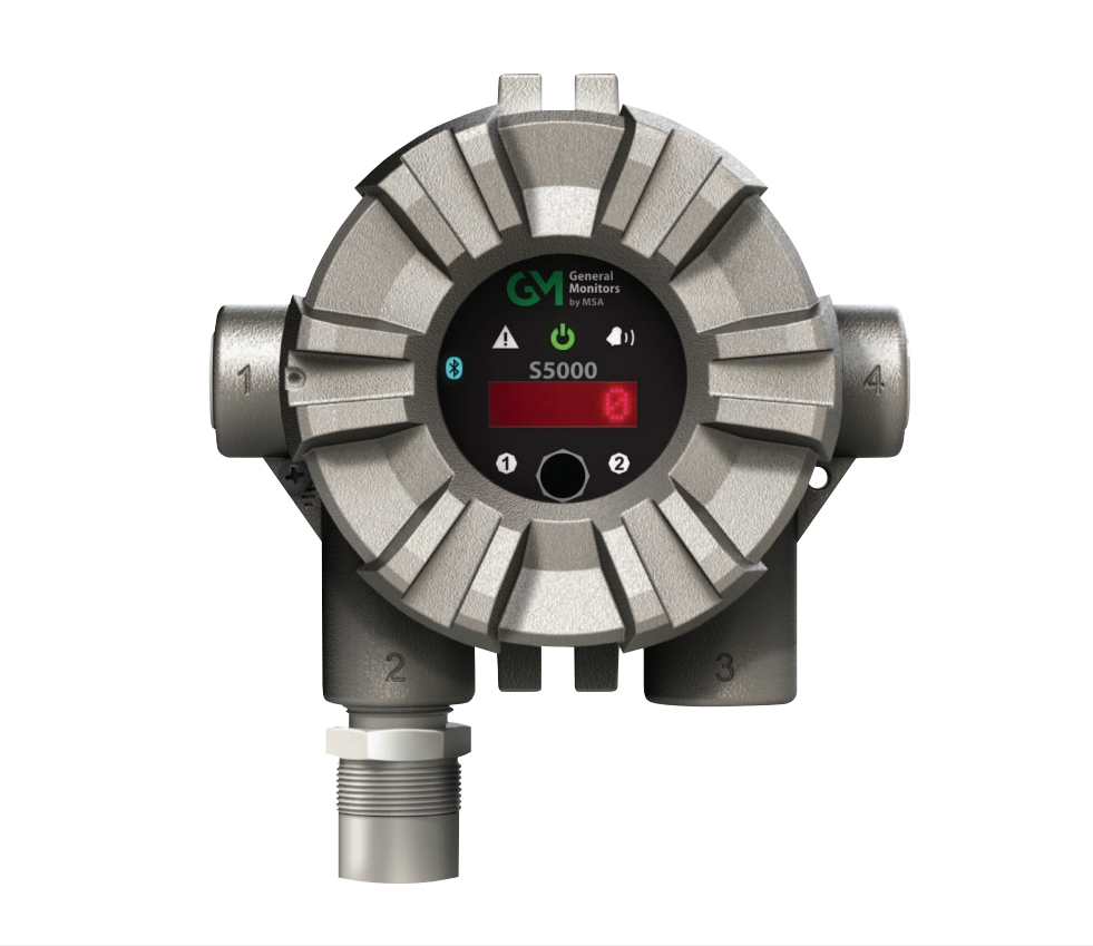
 Figure 1 S5000 Main DisplayIn addition to the red LED display, the S5000 uses six icons to indicate status. Green LED indicates power supply status. A yellow triangle and red bell indicate fault and warning or alarm conditions respectively. The Bluetooth® icon indicates that the Bluetooth® wireless technology is enabled on the device. Yellow “1” and “2” icon indicate which sensor gas reading isbeing displayed, or during configuration which sensor’s options are being accessed.
2.2 No Tool Interface
The S5000 does not require any tools or third party devices to change settings, reset alarms or perform any maintenance operation. The EZ touch button works through the glass and does not require opening the explosion proof enclosure. The EZ touch button works with bare fingers or with gloved hands, so long as the gloves are not black. See 4 Operation for moreinformation on navigating the menu with the EZ touch button. Figure 2 InterfaceThe user menu can also be accessed using the round GM magnet on the General Monitors logo.
2.3 Bluetooth® Wireless Technology
The S5000 comes by default with Bluetooth communication. Using the X/S Connect App on an appropriate smart phone or tablet, users are able to interface with the S5000 menu options in a larger and more user friendly setting. The Bluetooth communication can interact with the device within a maximum transmission distance of 70 feet (21 m).
WARNING!
Bluetooth operation is dependent upon signal availability of the wireless service(s) necessary to maintain the communication link. Loss of wireless signal will prevent communication of alarms and other information to linked devices. Take appropriate precautions in the event a loss of wireless signal occurs.
Failure to follow this warning can result in serious personal injury or death.
If ordered with Bluetooth, the device will be shipped with Bluetooth enabled. See 4 Operation for instructions on disabling Bluetooth.If the device was not ordered with Bluetooth it cannot be upgraded.
The S5000 and user provided communication device will need to be paired. This requires both devices to be in range and for a pairing sequence inputting a 6 digit pairing code. The instructions will be displayed on both the S5000 and communication device.
There are communication devices capable of being used in classified areas. Please contact your MSArepresentative for additional information.
2.4 Dual Sensing
The S5000 supports two Digital Sensors, or one IR Sensor point IR detector and one Digital Sensor simultaneously with four wire connections. However, the device will only support one passive sensor, either combustible catalytic bead or metal oxide semiconductor (MOS) sensors, based on the ATO configuration. Passive catalytic bead uses three wires, passive MOS uses four wires.The S5000 Gas Monitor generates two independent analog outputs; one for each sensor connected to the transmitter. Theanalog output associated with Sensor 1 also has the digital HART (Highway Addressable Remote Transducer)communication superimposed on the analog signal. If two sensors are connected, the digital HART communication carriesinformation for both sensors.
2.5 Retrofit Installations
The S5000 has the conduit entries located in the exact same orientation and distance from the wall and the mounting holes for attaching to a wall are identical to the S4000 Series detectors. Users will be able to re-use the existing wiring for the remotely mounted sensors.
2.6 XCell Sensors Optimized for Fixed Gas Applications
XCell toxic and combustible catalytic bead sensors are developed and manufactured by MSA. Now optimized for fixed gas applications, the XCell sensor platform is available in the S5000 and provides multiple benefits, including a standard 3-year warranty on all XCell sensors. One important optimization for fixed gas was incorporating the GM catalytic bead into the XCell sensor.The XCell Oxygen sensor does not use lead, but rather a non-consuming reaction chemistry. The XCell Oxygen sensor is expected to last well over 3 years and can be safely stored on the shelf for at least 1 year without sensor performance degradation. Changes in barometric pressure across the range of 86 kPA – 108 kPA have a negligible effect on the operation of the sensor.
2.7 TruCal Sensing Technology for CO and H2S Electrochemical Sensors
Using patented pulse check technology and proprietary Adaptive Environmental Compensation (AEC) algorithms, all XCell sensors with TruCal verify operation by actively adjusting the sensor output for changes in sensitivity. Some XCell sensors with TruCal also include Diffusion Supervision, which monitors the sensor inlet for obstructions that could prevent gas fromreaching the sensor. Every six hours, an electrical pulse stimulates the XCell sensor similar to having actual calibration gas applied, providing a snapshot of the sensor’s sensitivity at the time of the pulse. Using this sensitivity snapshot, the sensor can diagnose sensor failures like electrode poisoning, electrolyte leaking, or electrical connectivity issues. AEC uses the sensitivity snapshots provided by the pulse check to adjust sensor output, compensating for environmental impacts on sensor accuracy. If the AEC adjustment is greater than expected based on typical environmental impact variations, the transmitter LED’s will slowly flash GREEN, alerting users that the sensor should be calibrated to reset the AEC cycle. Users can also enable a Calibration Alert function that will send a milli-amp signal on the analog output to the control room. The result is a sensor that actively self-monitors for operation and accuracy, with far fewer manualcalibrations. Diffusion supervision actively monitors the sensor inlet for obstructions. If an obstruction is detected, the sensor will go into a fault mode to alert users and the control room that it is not seeing gas due to an obstruction. Objects residing directly on or in the sensor inlet that result in a significant impact to the gas path are very likely to be detected by Diffusion Supervision. Examples include paint, tape, water, and dirt. Small amounts of these materials can be visible on the inlet while not impacting the gas path enough to trigger a Diffusion Supervision Fault. A fault signal will only be sent out when the system determines that the amount of material that has accumulated on or inside the sensor inlet is negatively affecting the gas path. Actual TruCal sensor performance will depend on the application, background gas exposure, and environment. To validate XCell sensors with TruCal, it is recommended that users follow their regular calibration cycle and record the “as found” and “as left” values. This data can be used to extend the time between calibrations depending on the required specification ofthe application.
2.8 SafeSwap
The S5000 comes with patented SafeSwap technology, which allows users to change or replace XCell sensors without needing to power down the instrument. Swap delay is enabled on the S5000 by default; a feature that gives users a 2 minute window to change sensors without triggering a fault condition. SafeSwap and Swap Delay are only applicable for XCell sensors. For more information on SafeSwap and Swap Delay, see 6 Maintenance.
WARNING!
- As part of the product certification, it was verified that optional communication functions of this gas detection instrument while operating at the maximum transaction rate do not adversely affect the gas detection operation and functions of the instrument. The product certification, however, does not include or imply approval of the SafeSwap feature, communications protocol or functions provided by the software of this instrument or of the communications apparatus and software connected to this instrument.
- Follow the warnings below when removing or replacing sensors. Reference Figure 3 for component overview.– Never remove or replace a Sensor Body Assembly or an IR Sensor while under power or when explosive hazards are present.– Confirm that the area is free of explosive hazards before removing or replacing an XCell Sensor under power.– To remove an XCell Sensor, unscrew XCell Sensor three full turns, wait 10 seconds, and then remove the XCell Sensor completely.
Failure to follow these warnings can result in serious personal injury or death.
2.9 Housing
The S5000 comes in 316 Stainless Steel for the highest corrosion resistance. All housings have ¾” NPT conduit entries. Custom tags are available and easily attach to an integral ring. The JB5000 junction box comes in 316 Stainless Steel for the highest corrosion resistance. The housing is offered in ¾” NPT of M25 conduit entries.
2.10 Component Overview
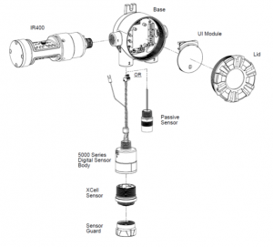 Figure 3 Exploded View
2.11 Label Overvi
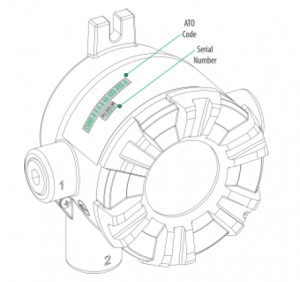
Figure 5 Board stack – Position of Labels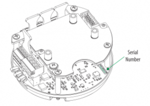 Figure 6 Digital Sensor – Position of Labels
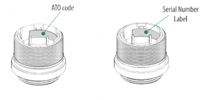 Figure 7 IR Sensor – Position of Labels
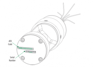
Figure 8 Passive Sensor – Position of Labels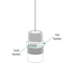
3 Installation
3.1 Installation Warnings – Read Before Installation
WARNING!
- Refer to 9 Appendix: General Certification Information before installation and operation.
- Some Digital Sensors are provided in a fritless sensor housing. The fritless sensor housing is labeled as Div 2 or Zone 2 and is approved for Div 2 or Zone 2 installations only. The protection method is Nonincendive or Type n respectively. Ensure all components are approved for the wiring method being used and in accordance with the National Electric Code of the country of use, any applicable local regulations, and this manual.
- As part of the product certification, it was verified that optional communication functions of this gas detection instrument while operating at the maximum transaction rate do not adversely affect the gas detection operation and functions of the instrument. The product certification, however, does not include or imply approval of the SafeSwapfeature, communications protocol or functions provided by the software of this instrument or of the communications apparatus and software connected to this instrument.
- Follow the warnings below when removing or replacing sensors. Reference Figure 3 for component overview.– Never remove or replace a sensor body assembly or an IR Sensor while under power or when explosive hazards are present.– Confirm that the area is free of explosive hazards before removing or replacing an XCell Sensor under power.– To remove an XCell Sensor, unscrew XCell Sensor three full turns, wait 10 seconds, and then remove the XCell Sensor completely.
- Plug all unused conduit entries with a suitably certified blanking/stopping plug.
- Do not paint the device. Avoid painting in areas where the S5000 and remote sensor junction box are located. If painting is required in an area where an S5000 or remote sensor has been installed, exercise caution to ensure paint is not deposited on the sensor inlet fitting. Paint solvents can also cause an alarm condition to occur or potentially poison electrochemical sensors.
- Protect the device from extreme vibration.
- Do not mount the sensing head in direct sunlight without a sunshield (P/N 10180254).
- IR Sensors contain no user- or field-serviceable parts and must be returned to the factory for repair. Any attempt to open the monitor will damage the unit and void the warranty.
Failure to follow these warnings can result in serious personal injury or death.
NOTICE
When installing the IR Sensor, under no circumstances should a pry-bar be applied to the two legs that support the unit’s reflectors during installation or removal of the sensor. Applying force to the legs can permanently damage the IR Sensor.
3.2 Reviewing Shipment and Identifying Product Model
To determine the sensor type and options, check the shipping carton.
Passive, Digital, and IR sensors are shipped attached to the S5000. Passive and IR Sensors are one-piece sensors. Digital sensors comprise two parts: the Sensor Body Assembly and the XCell Sensor. Sensor Body Assemblies must be installed and tightened using a strap wrench. Check the sensor details before attaching to the S5000 housing. The sensor details are listed on the inside of the XCell Sensor. Unscrew the XCell Sensor from the sensor body assembly and check the label on the inside for gas type, range,configuration ordered, serial number, and firmware revision number.
3.3 Product Installation Check List
Before Installation
- Review national electrical codes
- Review local procedural and building codes
- Determine optimum transmitter placement
- Determine wire requirements
- Determine mounting hardware requirements
- Review approvals and ensure suitability for installation
Mounting
- Attach appropriate sensor to housing or junction box (see 3.4.3 Sensor Orientation for proper sensor orientation)
- Mount transmitter or junction box using appropriate mounting hardware
- Confirm free air flow around the sensor
3.4 Mounting
 Refer to 9 Appendix: General Certification Information before installation. Some toxic gases are provided in a fritless sensor housing. The fritless sensor housing is labeled as Div 2 or Zone 2 and is approved for Div 2 or Zone 2 installations only. The protection method is Nonincendive or Type n respectively. Ensure all
Failure to follow this warning can result in serious personal injury or death.
3.4.1 Sensor Mounting Location
The best location for the transmitter and the sensor may not be the same location. Sensors should be placed in a location where a gas leak is most likely to be detected. When the best sensor placement would not allow the transmitter display to be easily viewed or accessed, a remote junction box can be used to mount the sensor remotely from the transmitter,allowing both to be installed in the optimum location. Two main factors should be considered when choosing a sensor location. The first is the density of the target gas relative to the air. Gases, such as propane, that are heavier than air should be placed near ground level while gases that are lighter than air should be placed above potential leak sources. Optimum sensor placement will depend on the surrounding processing equipment, such as pipes, valves, or turbines. MSA offers a gas and flame mapping service that systematically evaluates potential sources of leaks and recommends detector quantity and placement to create the most effective detection system.
3.4.2 Transmitter Mounting Location
The transmitter display should be mounted so that the screen is visible and easily accessed after installation. The electronics assembly inside the enclosure have one orientation inside the cylindrical housing. Take care to position the conduit entries and display so that the display is read in the correct orientation.
3.4.3 Sensor Orientation WARNING!
WARNING!
Mount the IR Sensor with the sensor inlet fitting extended horizontally from the main enclosure (see Figure 10 ) to preventthe build-up of particulate or liquid matter on the monitor’s optical surfaces. Mount the digital sensor with the sensor inlet fitting (see Figure 11 ) pointed downward; otherwise, the inlet may become clogged with particulate matter or liquids.
Failure to follow this warning can result in serious personal injury or death.
Sensor orientation will depend on the sensor type. If mounting an IR Sensor, whether locally on the transmitter or via remote junction box, the sensor should be mounted horizontally. If the IR Sensor is not mounted horizontally, the sensor will be prone to more frequent beam blocking issues due to accumulated dust and condensation on the surface of theIR Sensor. Figure 10 shows the correct and incorrect mounting orientations for the IR Sensor.
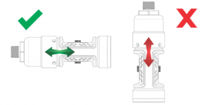
Figure 10 Correct and Incorrect Mounting Orientations for IR Sensor
All other sensors, including electrochemical, catalytic bead, oxygen, passive catalytic bead, and passive MOS should be mounted vertically with the gas inlet pointed downward. If the sensor is not mounted with the gas inlet facing down, it is more likely to become clogged with particulate matter or liquids. Figure 11 shows the correct and incorrect mounting orientation for digital sensors. Passive catalytic bead and MOS sensors come already installed on the transmitter housing.
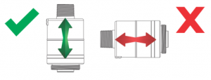 Figure 11 Correct and Incorrect Mounting Orientation for Digital Sensors
3.4.4 Connecting Sensor to Transmitter Housing or Remote Junction Box
Digital and IR Sensors are shipped attached to the main enclosure. The main sensor input is provided via a four-terminal connection that provides a digital interface for all sensor modules. Up to two sensors (excluding passive sensors) can be connected to a single transmitter with two analog outputs capable of representing the readings of the individual sensors. Passive sensors are shipped already attached and electrically wired to the device. Only one passive sensor can be used on a single S5000, and they are not interchangeable with other passive sensors or digital sensors. Consider the sensor dimensions when choosing a mounting location for the transmitter or junction box.
To connect the sensor:
- Loosen the set screw located on the lid using a 1.5 mm Allen wrench.
- Turn the lid counter-clockwise to remove.
- Pull out display module to expose terminal connections. Figure 12 Terminal Connections
- Route the cable from the sensor through a conduit entry hole in the enclosure so that the sensor is oriented in the correct position (see 3.6 Electrical Power Connections for details).(Repeat to attach a second sensor to the S5000 transmitter).
- Connect the sensor to the “Sensor 1” position on the electronics assembly. a) If using a second sensor, connect it to the second sensor position.NOTICE If only using one sensor and it is connected to “Sensor 2” position, the S5000 will enter Sensor Missing fault. See DisableSensor in 4.2.2 Sensor Setup for details on how to clear this fault. Figure 13 Connecting Sensor to the Figure 14 SOURCE/SINK Switch Location Stack and Grounding Terminal
- Verify the sensor connector is firmly seated on the terminal board.
- Attach the sensor’s ground to either of the grounding screws inside the S5000 housing.
- Set the analog output to SOURCE or SINK using tweezers, flat head screwdriver or similar tool.a) With the display board removed, locate “S1” switch on the main board (see Figure 14 ).b) Set “S1” switch in the required position:For SINK, set switch to the right side.For SOURCE, set switch to the left side.
- Replace the display module. Push firmly on the board stackNOTICE Ensure that the electronics assembly is fully engaged in the mounting holes. If not fully seated, the touch interfaceperformance can be negatively affected.
- Replace the cover by turning clockwise.
- Tighten the set screw located on the lid using a 1.5 mm Allen wrench.NOTE: The JB5000 junction box is not compatible with IR400 and passive sensors
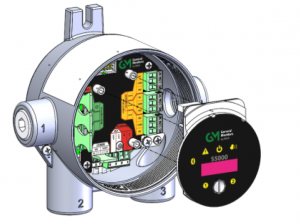 Figure 12 Terminal Connections
 Figure 13 Connecting Sensor to the Figure 14 SOURCE/SINK Switch Location Stack and Grounding Terminal
3.4.5 Integrated Mounting Points
The S5000 transmitter can be surface mounted without any additional brackets using the integrated mounting tabs.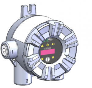 Figure 15 Integral Mounting Tabs
Mounting Points JB5000 Junction Box
The JB5000 junction box can be mounted directly using the 4 integrated 10-32 threaded holes on the back of the enclosureor with the use of a mounting bracket (P/N 10206570).
3.4.6 Adjustable Pipe Mount
A Universal Pipe Mount Kit (P/N 10176946) can be used to mount the S5000 on pipes ranging from 20-150 mm in diameter. Two brackets are mounted over the top of the integrated mounting tabs and fitted with an adjustable pipe band (not included).
 Figure 16 Adjustable Pipe Mount
3.4.7 Duct Mount
Duct mount kits are available for monitoring atmosphere inside flat or round ducts. Round duct mount kits are available for small ducts 12-20″ in diameter (P/N 10179323) and large ducts 20-40″ in diameter (P/N 10179324). The flat duct mount (P/N 10179322) is universal for flat ducts.
NOTICE
Consider the sensor type before choosing a duct mount location. IR Sensors should be mounted horizontally and all othersensors should be mounted vertically.
NOTICE
Air flow in the duct must be zero to ensure proper calibration.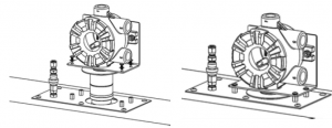 Figure 17 Flat Duct Mount
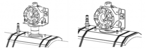 Figure 18 Round Duct Mount
3.4.8 Mounting with a Sunshield
A sunshield is required to protect the S5000 from direct sun light (P/N 10180254). The sunshield can be used in any of the mounting configurations.
 Figure 20 Sunshield with Universal Pipe Mount
 Figure 20 Sunshield with Universal Pipe Mount
3.4.9 Mounting with an SM5000 Sampling Module
An aspirated (P/N 10158101) and a DC pump (P/N 10043264) model are available for use with the S5000 with the Digital Sensor. For more information on mounting requirements and use with the SM5000 sampling modules, see the SM5000 operating manual(s).
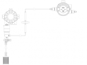
Figure 21 Mounting the SM5000 with a Digital Sensor
SM5000 is not for sale in EU.Diffusion Supervision must be disabled when using the SM5000.
3.5 Installing a Remote Sensor Junction Box
Sensors mounted remotely must use the S5000 junction box. The junction box housing is the same construction as the transmitter. The mounting options and instructions for connecting the sensor are the same for sensors connected directly to the S5000 transmitter housing. The junction box is available in 316 Stainless Steel. Sensors can be remote mounted up to 100 m from the transmitter housing, as long as the S5000 transmitter is mounted within maximum distance from the power supply, as indicated in Table 1 . The junction box does not have an illuminated display and has two connectors for attaching a single sensor input and an output connects to the transmitter. A 16 AWG 4 element cable with a braided shield should be used for the electricalconnection between the junction box and the S5000 transmitter. Specific cable recommendations are available upon request.
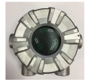 Figure 22 Junction Box
 Figure 23 Junction Box Electrical Connections
3.6 Electrical Power Connections
3.6.1 Electrical Warnings – Read before Connecting Power
WARNING!
- Before wiring the S5000 transmitter, disconnect the power source supplying the transmitter and ensure no hazardous atmosphere present; otherwise, electrical shock or ignition of hazardous gases could occur.
- Install wiring in accordance with the electrical code of the country in use, the local authority having jurisdiction and these installation instructions, as applicable.
- Do not make any connections to the S5000 main board or junction box input, output, and relay connections while under power. Making connections under power could lead to electrical shock or ignition of a hazardous atmosphere.
- Ensure that water and dirt are not able to enter the unit via the wire or conduit. If the unit is installed in a location known to be wet or damp, it is good practice to loop or bend the entry into the unit that prevents water incursion.
- The internal grounding terminal (located on the interior metal board stack plate) must be used for equipment grounding. The external grounding terminal is only to be used as a supplemental bonding connection where local authorities permit or require such a connection.
- As part of the product certification, it was verified that optional communication functions of this gas detection instrument while operating at the maximum transaction rate do not adversely affect the gas detection operation and functions of the instrument. The product certification, however, does not include or imply approval of the SafeSwap feature, communications protocol or functions provided by the software of this instrument or of the communications apparatus and software connected to this instrument.
- Follow the warnings below when removing or replacing sensors. Reference Figure 3 for component overview.– Never remove or replace a sensor body assembly or an IR Sensor while under power or when explosive hazards are present.– Confirm that the area is free of explosive hazards before removing or replacing an XCell Sensor under power.– To remove an XCell Sensor, unscrew XCell Sensor three full turns, wait 10 seconds, and then remove the XCell Sensor completely.
Failure to follow these warnings can result in serious personal injury or death.
3.6.2 Retrofit Applications with S4000CH, S4000TH, or TS4000H
The S5000 was designed to be easily retrofitted with existing S4000CH, S4000TH, and TS4000H wiring. When replacing an existing S4000CH, S4000TH, or TS4000H with the equivalent S5000 sensor technology, the following items need to be checked in order for the S5000 to operate:
- Wire gauge needs to be 18-14 AWG
- Sufficient power must be supplied to the S5000 in accordance with the maximum wire lengths. (See the tables in3.6.4 Power Load Requirements and Maximum Mounting Distances)If these requirements are met, performance of the S5000 should meet the noise immunity standard equivalent of the S4000CH, S4000TH, and TS4000H using the existing wiring; However, the installation may not meet the latest EMC EN50270 noise immunity standard that the S5000 meets with the grounding and wiring scheme as indicated in this manualand corresponding I/O drawing.
3.6.3 Electrical Hardware Requirements
Braided shielded, twisted pair, instrument quality wire or cable should be used to minimize the possibility of noise interference and contact with other voltages. Selection of shielded cable must comply with local requirements. Conduit, in addition to braided shielded wire, may also be needed in areas where a large amount of electrical noise isexpected. All cable shields should be terminated to earth ground at one end only. The S5000 has a four-wire power terminal, one four-wire communication terminal, and three four-wire sensor terminals. Relays can be added as an option. Terminals for power and relays can take wires up to 12 AWG while all other terminals take wires up to 14 AWG. Four conductors are also required for the S5000 remote junction boxes.
Incoming power and signal cables should be a braided shield cable such as Alpha Wire 3248 or equivalent. The braided shield must be terminated to the board stack as shown in Figure 27 , or alternatively, the earth ground at the user’s power source location.An external Class 2 power supply is required to supply 12-30 VDC to the S5000. Incoming power and signal cables should be a braided shield cable such as Alpha Wire 3248 or equivalent.
3.6.4 Power Load Requirements and Maximum Mounting Distances
Consider future needs when selecting cable size and power supply. The maximum distance between the S5000 transmitter and the power supply depends on the sensor configuration (sensing technology and one or two sensors), wire gauge, and the power supply voltage. The table below outlines the maximum transmitter mounting distances. First determine if thesensor(s) will be locally or remotely mounted. Then choose sensor type(s). The corresponding maximum power and mounting distances by wire gauge are shown.
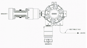 Figure 24 Local Sensors
Table 1 Maximum Mounting Distance for Local Sensors, Imperial Units
1- When sizing a system’s 24 V supply, a 1 A inrush current with a 1 ms duration should be considered for each device on the power supplyAssumes transmitter was ordered with relays
Table 2 Maximum Mounting Distance for Local Sensors, Metric Units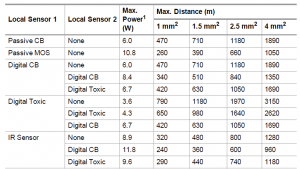
1- When sizing a system’s 24 V supply, a 1 A inrush current with a 1 ms duration should be considered for each device on the power supplyAssumes transmitter was ordered with relays
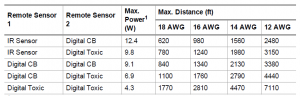
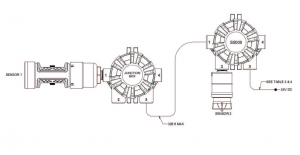 Figure 25 Local and Remote Sensors
Table 3 Maximum Mounting Distance for Local and Remote Sensors, Imperial Units
1- When sizing a system’s 24 V supply, a 1 A inrush current with a 1 ms duration should be considered for each device on the power supplyAssumes transmitter was ordered with relays
Table 4 Maximum Mounting Distance for Local and Remote Sensors, Metric Units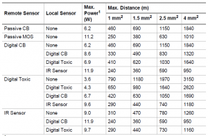
1- When sizing a system’s 24 V supply, a 1 A inrush current with a 1 ms duration should be considered for each device on the power supplyAssumes transmitter was ordered with relay

Figure 26 Remote Sensors Table
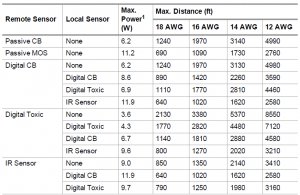
Table 5 Maximum Mounting Distance for Remote Sensors, Imperial Units
1- When sizing a system’s 24 V supply, a 1 A inrush current with a 1 ms duration should be considered for each device on the power supplyAssumes transmitter was ordered with relays
Table 6 Maximum Mounting Distance for Remote Sensors, Metric Units
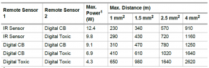
1- When sizing a system’s 24 V supply, a 1 A inrush current with a 1 ms duration should be considered for each device on the power supplyAssumes transmitter was ordered with relays
3.6.5 Instructions for Power and Analog Output
Read all electrical warnings and wiring requirements before connecting power to the S5000.Failure to follow this warning can result in serious personal injury or death.
Connector for HART analog output and power are provided to increase ease of connecting power. Connect power and remote sensor cable shields to shield terminals on the main PC board. Provide shield terminations inside he sensor housing as indicated on the installation outline drawing.
- Remove the cover by turning counter-clockwise.
- Remove the display module to expose the wiring terminations and sensor connections.
- Remove the 5.08 mm pitch connector for power supply. The power connector is larger than other 3.81 mm pitch connectors.
- Use a small flat head screw driver to open wire entries on connector.
- Insert wires to connector so that when installed each wire is in the correct location.1. +DC2. -DC3. mA1 – analog output of sensor 14. mA2 – analog output of sensor 2
- Tighten screws on connector and tug gently on wires to ensure they are secure.
- Attach the connector to the board stack.
- Make sure the appropriate wires are in the correct terminals.
- Remove enough of the wire housing to expose the 3-4 inches of the cable shielding, but do not expose so much that it goes beyond the cable entry.
- Attach the cable, shielding exposed, to the grounding point.
- Replace the display module. Push firmly on the board stack where indicated.
- Replace the S5000 cover by turning clockwise. Be sure to align threads to avoid cross-threading. Figure 27 Connecting Power and Grounding Cable
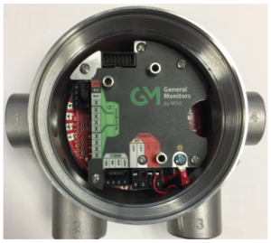 Figure 27 Connecting Power and Grounding Cable
NOTICEEnsure that the electronics assembly is fully engaged in the mounting holes. If not fully seated, the touch interfaceperformance can be negatively affected.
Care must be taken to ensure the S5000 inside glass surface glass is free of smudges/dirt and grease. Dirt and grease caninterfere with the touch interface of the display.
S5000 Installation Outline Drawings
Table 7 Installation Outline Drawings
| Model | Document No. |
| S5000 | 324102 |
3.6.6 Relay Electrical and Power Connections
Relay Board Stack OverviewThe S5000 can be purchased with three relays. Two of the relays can be configured for either de-energized (default) or energized and latching or non-latching. The third relay is a dedicated fault relay. All electrical connections to internal relays can be made directly on the PC board. The board is labeled for Normally Open (NO) and Normally Closed (NC) de-energized state.

Relay Specifications
Table 8 Relay Specifications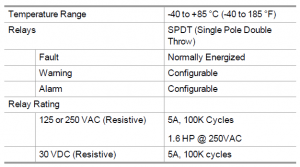 If using AC power, the relay wires should not be run within the same conduit or cable tray as the DC power supplied to theS5000 or the S5000 junction box. A separate wire entry on the device should be used for AC power connected to the relays. The S5000 is built with an additional wire entry to allow this.
Exceeding the volt-amp rating of the relay can cause damage to the switching contacts.
Relay Connections to Inductive Loads
If connecting the relays to motors, fluorescent lighting, or other inductive loads, it is necessary to suppress any sparks or inductive feedback that may occur at the relay contact. These effects may render the unit inoperative.One way to reduce these effects is to install a Quencharc® (P/N 630413) across the load being switched.
Fault Relay Wiring and Configurations
The Fault relay state in non-fault operating condition is Energized and terminal connections are supplied for Normally Closed and Normally Open. The energized fault relay setting provides an electrical path for fail-safe relay operation. In the event of any failure, including loss of power, the relay will change to the de-energized state to indicate a fault condition.The Fault relay state cannot be reconfigured
Relay Energy State and Terminal Connections
The S5000 relay states are labeled for the default de-energized state. The alarm/warning relay energy state can be changed on the device, which will exchange the normally open and normally closed terminals. The preferred relay energy state should be determined before making connections. Table 9 shows the terminal connections by energy state and isapplicable to both relay 1 and relay 2.
Table 9 Relay Terminal Connections by Energy State

4 Operation
WARNING!
Refer to 9 Appendix: General Certification Information before installation and operation.Failure to follow this warning can result in serious personal injury or death.
The S5000 Series gas monitor is factory calibrated and shipped with the most common default options to minimize set up effort. Using sensors, the device tests the ambient air and triggers an alarm as soon as the gas exceeds a specific concentration level.
4.1 Startup
4.1.1 Initial Startup
- The first time the S5000 is powered on, the following will appear on the display:
- S5000
- Software Version No.
- Sensor Warm-up
- Wait
The S5000 will remain in Start-up mode in which the fault relay is de-energized and the analog output is 3.5 mA by default. The time the S5000 stays in Start-up mode depends on the sensor.Oxygen and Carbon Monoxide sensors require a 30 minute warm-up time before being fully functional. The device will be in fault during the 30 minute start-up time. All other sensor start-up times vary, the unit will be in fault for the first 2 minutes of the start-up time and the analog output signal will be at the maintenance level (3.5 mA default). A full calibration is recommended after one hour of a sensor being installed and acclimated to the environmental conditions. See 5 Calibration for calibration details
4.1.2 Sensor Warm Up Times
WARNING!
For optimal sensor performance, allow sensors 24 hours to acclimate to application conditions before performing an initial calibration
Failure to follow this warning can result in serious personal injury or death.IR Sensor: ≤ 10 minH2S: ≤ 5 minSO2: ≤ 5 minCl2: ≤ 10 minNH3: ≤ 5 minCat Bead: ≤ 5 minPassive MOS: ≤ 5 minPassive Cat Bead: ≤ 5 minCO: 30 min (see note)O2: 30 min
Carbon Monoxide sensor gas codes D10, D11, D12, and D14 may require initial warm-up periods longer than 30 minutes. If the 30-minute warm up is over, the sensor may show a positive reading that exceeds alarm levels. In the event of a shortterm power outage, the warm-up time for carbon monoxide gas codes D10, D11, D12, and D14 will be significantly less.See the table below to estimate required warm-up time.
Table 10 Warm Up Times CO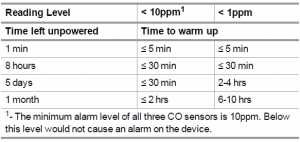
1- The minimum alarm level of all three CO sensors is 10ppm. Below this level would not cause an alarm on the device.
4.1.3 Startup after Power Failure
If the S5000 loses power, all of the settings are saved to the internal memory. When power is restored to the device, it will go back to the same settings as before the loss of power. To check the settings, go through the menu or view on the X/S Connect App.
4.2 Settings
The S5000 is a tool free transmitter. The infrared EZ touch button on the face of the display can be used to navigate through the menu structure. The button is designed for use with fingers with a “press” and “release” action, and works best without gloves. The button works the same as the magnet does with the S4000 menu.
Changing a value
- Press and hold EZ Touch button.
- Wait for relevant menu to scroll (each menu scrolls twice).
- Release to enter menu while it is scrolling.
- Use Press and Release function to change values.
The EZ touch interface can be disabled, but will require a password. Menu settings can also be activated using a magnet on the General Monitors logo. Values that are changed in the menu are saved after main setup loop “Finished”, except for sensor range selection under sensor setup. Each menu ends with “Finished?” scrolling twice on the display. If the button is not touched during “Finished?”, the menu will begin at the start again and scroll through the options and values again. The new values thatwere entered will be displayed on the first pass. When user exits a menu by touching “Finished?” and there isn’t a second sub menu, the previous menu will be displayedstarting at the menu that had just been used.
Some instrument settings are only configurable through Bluetooth® X/S Connect App, Modbus, or HART. See4.4 Setting only configurable via Bluetooth®, Modbus, or HART.
4.2.1 Instrument Settings
The following settings are saved to the device memory and will not change if the sensor type is changed.
- Scroll to Settings.
- Select Instrument.
- Select to enter the menu.
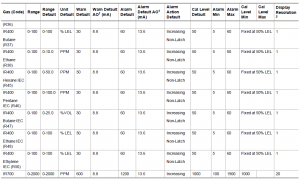
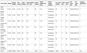
Table 11 Default Device Settings
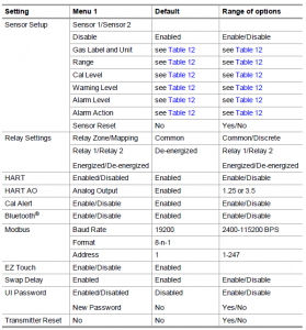
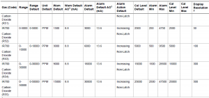
Table 12 Digital Sensor Default Settings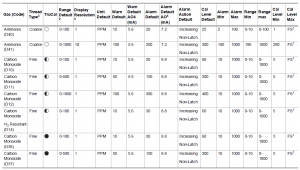
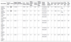
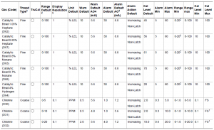

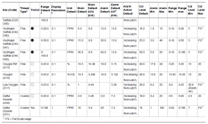

4.2.2 Sensor Setup
Configure gas unit, range, calibration level (i.e. span value), warning and alarm levels and whether they are latching or nonlatching.
The Sensor Setup menu will go through each sub menu before exiting Sensor Setup.
- Hold finger on button while menu selections scroll across screen.
- Remove finger when Setup menu appears.
- Touch button when Sensor Setup appears (first option).
- The following menus are available under Sensor Setup. When “Finished?” is selected under each of the following menus, the next menu will start.a) Sensor 1/Sensor 2b) Disablec) Gas Label & Unitd) Rangee) Cal Level (Span Value)f) Warning Levelg) Warning Actionh) Alarm Leveli) Alarm Actionj) Diffusion Supervisionk) Reset
- Select “Finished?” after the Reset menu to go back to the main Setup menu.
Disable Sensor (for Digital Sensors Only)
When removing a sensor from the transmitter while under power, the S5000 will enter a Sensor Missing fault condition after the two minute Swap Delay period has expired (if enabled). If Swap Delay is disabled, the transmitter will go into Sensor Missing fault immediately after removing the sensor from the transmitter. If the system is off at the time a sensor isremoved, the transmitter will go into fault after its startup sequence. This fault condition can be removed by disabling the affected sensor position. Disabling a sensor removes the fault and stops communications with the sensor, the sensor’s reading on the display is removed, and the mA channel for that sensor position is set to 0 mA. By default, the S5000 has the Sensor 2 position disabled. If at any time a sensor is connected to a position that is disabled, the device will automatically enable that sensor position.
To disable the sensor after removal:
- Go to Sensor Setup menu.
- Touch button when Disable appears on screen.
- Select Sensor 1 or Sensor 2. Current status (enabled/disabled) displays.
- Touch button to toggle to desired status.
- Select “Finished?”.
To remove a sensor that is already installed, the sensor must first be removed. The sensor cannot be disabled while it is installed on the transmitter.The device only allows a sensor to be disabled after the transmitter has gone into Sensor Missing fault. Only one sensor can be disabled at a time. The transmitter will not allow both sensors to be disabled at the same time. This only applies to digital sensors (gas codes starting with D).
Gas Label and Unit
Change the gas unit displayed. For toxic sensors, select from ppm, mg/m3, and μm/mol.
- Go to Sensor Setup menu.
- Touch button when Gas Label & Unit appears on screen. The Gas type and unit will appear on the screen.
- Touch button while the units scroll to change to another unit.
- Touch button when “Finished?” is displayed to exit.
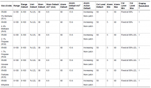
Sensor RangeSet the range of the sensor. To see what ranges are possible for the sensor type, see Table 12 , Table 13 , and Table 14 .Ensure that the IR700 range is configured to match that of the sensor
- Go to Sensor Setup menu and select “Finished?” until Range displays. Range will scroll across the screen and the current Range will be displayed.
- Hold finger on button to scroll quickly through values or touch button repeatedly to move through values more slowly.
- When the desired value is displayed, wait until “Finished?” scrolls across screen.
- Touch button when “Finished?” is displayed to exit.
Cal Level (i.e. Span Value)
Set gas concentration used during calibration.
- Go to Sensor Setup menu and select “Finished?” until Cal Level displays. Cal Level will scroll across the screen and the current Cal Level will be displayed.
- Hold finger on button to scroll quickly through values or touch button repeatedly to move through values more slowly.
- When the desired value is displayed, wait until “Finsihed?” scrolls across screen.
- Touch button when “Finished?” is displayed to exit to save the sensor parameter.
Warning Settings
Set Warning level and whether warning is latching or non-latching.
- Go to Sensor Setup menu and select “Finished?” until Warning displays. Warning will scroll across the screen and the current Warning level will be displayed.
- Hold finger on button to scroll quickly through values or touch button repeatedly to move through values more slowly.
- When the desired value is displayed, wait until Latching option appears.
- To change warning to latching or non-latching, touch button when the option is displayed.
- Touch button when “Finished?” is displayed to exit.
Alarm Settings
Set Alarm level and whether warning is latching or non-latching.
- Go to Sensor Setup menu and select “Finished?” until Alarm displays. Alarm will scroll across the screen and the current Alarm level will be displayed.
- Hold finger on button to scroll quickly through values or touch button repeatedly to move through values more slowly.
- When the desired value is displayed, wait until Latching option appears.
- To change alarm to latching or non-latching, touch button when the option is displayed.
- Touch button when “Finished?” is displayed to exit.
Alarm Relay Settings is the last Sensor Setup menu. “Finished?” will save changes and take the user back to Setup menus.If the Alarm Relay is configured to be non-latching, the Alarm Relay output must be connected to an auxiliary device that performs the latching function.
Diffusion Supervision
Diffusion supervision actively monitors the sensor inlet for obstructions. If an obstruction is detected, the sensor will go into a fault mode to alert users and the control room that it is not seeing gas due to an obstruction. Objects residing directly on or in the sensor inlet that result in a significant impact to the gas path are very likely to be detected by DiffusionSupervision. Examples include paint, tape, water, and dirt. Small amounts of these materials can be visible on the inletbwhile not impacting the gas path enough to trigger a Diffusion Supervision Fault. A fault signal will only be sent out when the system determines that the amount of material that has accumulated on or inside the sensor inlet is negatively affectingthe gas path.
Even if a Diffusion Supervision Fault has not been triggered, it is good practice to clear any foreign material fromthe sensor inlet if any is observed while inspecting the sensor.
To enable or disable Diffusion Supervision:
- Go to Sensor Setup menu.
- Touch button when Diffusion Supervision appears.
- Select Sensor 1 or Sensor 2. Current status (enabled/disabled) displays.
- Touch button to toggle to desired status.
- Select “Finished?”.
Sensor Reset – Last option in Sensor Setup
NOTICE
The sensor goes into a Sensor Configuration Reset fault (F007) and must be calibrated after a sensor reset. All settings, including Alarm Set Point and Calibration Values, will be returned to factory defaults. The sensor default values can be restored by resetting the sensor. During sensor reset, the analog output displays the sensors current gas value (i.e. 0 % LEL = 4 mA) during the 120 s count down.
To reset sensor to factory default:
- Go to Sensor Setup menu.
- Go through menus selecting “Finished?” at the end of each option.
- Touch button when Reset Setting scrolls across screen.
- Touch button to change to yes.
- Touch button when “Finished?” is displayed to exit.
This is the last Sensor Setup menu. “Finished?” will take the user back to Setup Menus and will save any changes made.
4.2.3 Relay Settings
Relay Setup is used to change the relay zone mapping and energized/de-energized settings.
Relay Zone/Mapping
- Hold finger on button while menu selections scroll across screen.
- Remove finger when Setup menu appears.
- Touch button when Relay Setup is displayed. Current setting of Zone/Mapping will be displayed (Common/Discrete).
- Touch button again will toggle the setting.
- If setting is changed, touch button when “Finished?” is displayed to save the change and move on to next setup. If no change is made, the menu will move on to next setup after two screen scroll rotation. Relay 1 and Relay 2 can be configured for common and discrete modes via the device display menu or X/S Connect app.
Common mode is the default relay mapping setting. In Common mode, Relay 1 is actuated by Alarm 1 on either sensor, and Relay 2 is actuated by Alarm 2 on either sensor.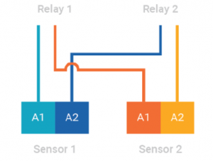 Figure 29 Common Mode Relay Map and Alarm Actuation
Discrete mode allows a separate action for each sensor. Relay 1 is actuated by Sensor 1 alarms and Relay 2 is actuated by Sensor 2 alarms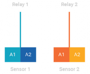 Figure 30 Discrete Mode Relay Map and Alarm Actuation
Horn mode is designed to allow local acknowledgment of a relay-triggered horn, while the alarm state is still present. All alarms on both sensors trigger both relays, however the second relay can be acknowledged through the “Reset” entry in UI menu by touching the EZ touch button or applying magnet to the GMI logo.
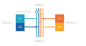 Figure 31 Horn Mode Relay Map and Alarm Actuation
Energized/De-energized
- Relay 1 and Relay 2 will scroll across screen alternatively.
- Touch button when Relay 1 or Relay 2 is scrolling.
- Touch button to show the current setting (energized/de-energized).
- Touch button again will toggle the setting.
- Touch button when “Finished?” is displayed to exit from Relay setting.
4.2.4 HART SettingsThere are two HART menus under Setup. HART Setup is used to Enable/Disable HART. HART AO Setup is used toconfigure the analog output signal for HART.
Enable/Disable HART
- Hold finger on button while menu selections scroll across screen.
- Remove finger when Setup menu appears.
- Touch button when HART Setup is displayed. The current HART setting is displayed (Enabled or Disabled).
- To change the availability of HART, touch button to change to the opposite state.
- Touch button when “Finished?” is displayed to exit.
4.2.5 HART AO
- Hold finger on button while menu selections scroll across screen.
- Remove finger when Setup menu appears.
- Touch button when HART AO Setup is displayed. The current HART analog output signal is displayed.
- To change the HART output signal, touch button to change to either 1.25 or 3.5.
- Touch button when “Finished?” is displayed to exit.
4.2.6 Calibration Alert
Sensors with TruCal technology actively monitor sensor and adjust sensitivity without any manual intervention. When equipped with Diffusion Supervision, TruCal will also monitor the sensor inlet for obstructions while Diffusion Supervision is enabled. These sensors do not need to be calibrated on a static maintenance cycle. When a manual calibration is recommended, the sensor will detect this and slow flash either the left green LED or right green LED indicating that calibration is recommended for sensor 1 or sensor 2 respectively. Users can also enable Calibration Alert so that an analog output signal is sent to the control room when a calibration is recommended. Whether or not the calibration alert is enabled, if gas is detected by the sensor, the S5000’s analog output and display will follow the gas reading.
To Enable or Disable Calibration Alert:
- Hold finger on button while menu selections scroll across screen.
- Remove finger when Setup appears.
- Touch button when Cal Alert is displayed. The current Cal Alert setting is displayed (Enabled/Disabled).
- Touch button to toggle desired status.
- Touch button when “Finished?” is displayed to exit.
4.2.7 BluetoothEnable/Disable Bluetooth
If the device is ordered with Bluetooth, it will come enabled by default. If unit is not ordered with Bluetooth, it cannot be retroactively added. This menu will not be displayed if the device was ordered without Bluetooth.
- Hold finger on button while menu selections scroll across screen.
- Remove finger when Setup menu appears.
- Touch button when Bluetooth Setup is displayed. The current Bluetooth setting is displayed (Enabled or Disabled).
- To change the Bluetooth availability, touch button to change to the opposite state.
- Touch button when “Finished?” is displayed to exit.
Bluetooth Pairing
The device memory has the ability to store up to 25 mobile devices in its memory. If a 26th device is paired, the memory will erase the first device stored in its memory. Each time a device is paired, it is logged as an event that is viewable in the X/S Connect App.The S5000 blue LED in the middle left of the display will flash when a device is paired with it as a visual indication of the pairing. Once paired with an S5000, the user will be able to connect to the same S5000 remotely and without a password, unless over 25 other devices are paired with the same S5000 afterwards. To pair with the S5000:
- Download the X/S Connect App from the Google Play Store or the iOS App Store.
- Open the X/S Connect App.
- Select “Pair” for the S5000 that you would like to connect with.
- (First Time Only) Enter Pairing Code on S5000 display.
- First Time Only) Accept pairing by touching button on S5000 display.
Bluetooth Security
The Bluetooth connection is encrypted and secured with a unique six digit pin that must be confirmed on the mobile device and acknowledged on the detector display. All of the previously paired devices can be erased from the S5000 to provide additional security and control.
To reset all device pairings:
- Scroll to Settings.
- Scroll and select Bluetooth
- Scroll and select “Reset All”.
- Select “Continue”.
NOTICE Reset All will delete all paired device memory. All devices will have to re-initiate pairing at the device.
Bluetooth Tag ID
See 4.3.6 Bluetooth FCC/IC ID to view Bluetooth Tag ID.4.2.8 Modbus Settings
The Modbus Setup menu consists of three configurable sub menus: Baud Rate, Format and Address.
- Hold finger on button while menu selections scroll across screen.
- Remove finger when Setup menu appears.
- Touch button when Modbus Setup is displayed.
Modbus Baudrate
- Go to Modbus Setup menu. Baudrate option is the first submenu. Baudrate will scroll across display followed by the current Baudrate setting.
- Touch the button to change to one of the following baudrate options:a) 2400b) 4800c) 9600d) 19K2e) 38K4f) 115K
- Touch button when “Finished?” is displayed to exit.
Modbus Address
- Go to Modbus Setup menu and select “Finished?” until Address is displayed. Address will scroll across display followed by the current Address setting.
- Hold finger on button to scroll quickly through values or touch button repeatedly to move through values more slowly. Address options range from 1-247.
- Touch button when “Finished?” is displayed to exit.
4.2.9 EZ Touch Button
The device has a single button that allows the user to change configurations without the use of a magnet or any other tool.Disabling the EZ Touch button requires the user to access menus with a magnet or via HART, Modbus, or Bluetooth.
- Hold finger on button while menu selections scroll across screen.
- Remove finger when Setup menu appears.
- Touch button when EZ Touch is displayed. he current EZ Touch setting is displayed (Enabled or Disabled).
- To change the EZ Touch availability, touch button to change to the opposite state. After disabling and selecting “Finished?”, the user will need a magnet to enable the setting. Otherwise it will not be possible to navigate the S5000 menus.
- Touch button when “Finished?” is displayed to exit.
4.2.10Swap Delay
Swap Delay allows the user a brief window to change an XCell sensor without the device going into a fault condition. Once a sensor is disconnected from the transmitter, the user will have 2 minutes to reconnect a sensor. During this time, the device display and analog output will go to its Maintenance level. If a sensor is reconnected or replaced during the 2 minutewindow, the new sensor’s countdown sequence will begin and the analog output will remain at the Maintenance level. After the sensor countdown is complete, the analog output will return to reporting a live gas reading. If a sensor is not reconnected after the 2 minute window, the S5000 will enter a fault condition. All XCell Sensors have Swap Delay and do not need to be disconnected from power while changing sensors. For more details on how to change sensors, see 6.2 Replacing an XCell Sensor. Swap Delay is enabled on all S5000 transmitters by default.
NOTICEThe transition to maintenance mode during the 2 minute Swap Delay window and sensor countdown will not trigger theFault Relay. The Fault Relay will only be triggered when the device enters a fault condition.
To change Swap Delay status:
- Hold finger on button while menu selections scroll across screen.
- Remove finger when Setup menu appears.
- Touch button when Swap Delay is displayed. The Swap Delay status is displayed (enabled or disabled).
- To change the Swap Delay status, touch button to change to either enabled or disabled.
- Touch button when “Finished?” is displayed to exit.
4.2.11UI PasswordEnable/Change Password
Enabling and changing the password is within the same menu. Enabling password will require the user to enter the password before entering any of the settings menus. The password entry screen defaults to 0000 and is disabled by default.If the password is lost, call GM Customer Service at +1-949-581-4464.
- Hold finger on button while menu selections scroll across screen.
- Remove finger when Setup menu appears.
- Touch button when UI Password Setup is displayed. The current UI Password setting is displayed (Enabled or Disabled).
- Touch button to change to the opposite state.
- Touch button when “Finished?” is displayed to save the enable/disable setting. Next menu “New Password?” is displayed is for setting password. Default password is 0000 if enabled.
- To change password, touch button when “No” appears on screen to change option to “Yes”.
- Touch button while “Finished?” is displayed to save change.
- The password entry screen will display a current password and each digit will blink for 4 seconds starting from left.
- While blinking, touch button to change desired numbers. The range is from 0 to 9 for each digit and 0000 to 9999 for digits.
- After changing the password, select “Finished?” to store the new password in the system.
Enter Password (if password is enabled)
If a password is enabled, the user must enter the password before entering any of the settings menus. The password entryscreen defaults to 000 and is disabled by default
- Holding finger on button will display rotating left arrow then “password”.
- Remove finger when UI Password appears.
- The password entry screen will display with 0 and each digit will blink for 4 seconds starting from left.
- While blinking, touch button to change the desired numbers. The range is from 0 to 9 for one digit and 0000 to 9999 for all 4 digits.
- If the password is correct, holding finger on the button again will display rotating left arrow then go into the menu items.
As long as the setup menu is active, no password is required to enter again. If menu was not active for 30 seconds, the password will be required again.
4.2.12Transmitter Setting Reset
The transmitter default values can be restored by resetting the main board. The unit will restart after the reset and the unit may go into sensor fault. During transmitter reset, the analog output displays 1.25 mA.
NOTICE : Verify all sensor settings (calibration level and alarm values) after resetting transmitter. Sensors may require recalibration to clear a fault after resetting transmitter.
4.3 Info Menu – Viewing Device StatusThis section describes how to view the following options:
- Display Current System Time
- Change System Time
- Sensor Life and Health Status
- Last Calibration Dates
- Non-critical Faults
- Device Tag
- Bluetooth ID
4.3.1 AO Type
- Go to Info menu and select AO Type. The AO type selected for this unit, Source or Sink, will scroll across the screen twice.
- Touch button when “Finished?” is displayed to exit.
4.3.2 View or Change System Time
- Go to Info menu and select System Time.
- Hold finger on button while menu selections scroll across screen.
- Remove finger when Info is displayed.
- Touch button when System Time is displayed. The current date followed by the current time will scroll across the screen twice.
- Touch button when Change Time displays if the current date and time are not correct.
- If selected, change the following values using the button and selecting “Finished?” after each entry:a) Monthb) Dayc) Yeard) Houre) Minutes
- Touch button when “Finished?” is displayed to exit.
You can also use the X/S connect app to sync time and date with a mobile device.
4.3.3 Last Calibration
- Go to Info menu and select Last Calibration. The last Calibration and Zero Calibration dates will scroll across the screen twice.
- Touch button when “Finished?” is displayed to exit.
4.3.4 Non-Critical Fault Log
- Go to Info menu and select Non-Critical Fault. Each of the last 10 faults will scroll across the screen twice.
- At the end of the fault log, menu goes back to Info menu options.
The user will not be asked to exit with “Finished?” at the end of this menu.
4.3.5 Device Tag
- Go to Info menu and select Device Tag. The current Device Tag name will scroll across screen.• DEFAULT – GM_S5K_0• The device tag name can be changed via Modbus or HART and is limited to 8 characters.
- After the Device Tag name scrolls across screen twice, menu goes back to Info menu options.
The user will not be asked to exit with “Finished?” at the end of this menu.
4.3.6 Bluetooth FCC/IC ID
- Go to Info menu and select Bluetooth FCC/IC ID. The current Bluetooth FCC/IC ID will scroll across screen. The Bluetooth FCC/IC ID cannot be changed and is unique to the device.
- Touch button when “Finished?” is displayed to exit.
4.3.7 Sensor Life and Health Status (only displayed if XCell Sensor is connected)
- Select Info.
- Select Sensor Status.If only one sensor is installed, the device displays the Life & Health status for Sensor 1.If two sensors are installed, “Sensor Selection” will be displayed.
- Select the desired sensor (Sensor 1 or Sensor 2) and touch button when “Finished?” is displayed.
The Life and Health information reports the general health of the sensor. XCell sensors with TruCal (Hydrogen Sulfide and Carbon Monoxide) calculate current sensor sensitivity using automated pulse checks. The pulse stimulates the sensor with a response similar to having actual calibration gas applied. The stimulated response is compared to the last calibration and will make adjustments to sensitivity to match the last calibration. When the required adjustment is greater than the accuracy of the algorithm’s adjustment, the sensor will call for a calibration.
All Digital Sensors, including catalytic bead and oxygen, will show life health status as ‘Good’ or ‘Fair’ with the following calculation: Good condition occurs when the current calibrated span sensitivity is greater than 50% of the way between the initial calibration sensitivity and the end-of-life span sensitivity. Fair condition occurs when the current calibrated span sensitivity is less than 50% of the way from the initial calibration sensitivity and the end of life span sensitivity.
NOTICEUsing expired calibration gas or the incorrect calibration gas can result in a premature “Fair” status.
4.4 Setting only configurable via Bluetooth®, Modbus, or HART
The following settings are only configurable through Bluetooth®, Modbus, or HART.
- AO Custom Levels
- Relay Zone – Horn Mode
- Unit Device ID/Tag
- Alarm Direction
- Alarm Enable/Disable
4.4.1 AO Custom Levels
S5000 offers three factory defined analog outputs (AO) level sets, i.e., 0 mA with HART disabled, or 3.5 mA and 1.25 mA with HART enabled. Users can also specify their own custom AO levels for each transmitter mode. The Maintenance AO level is used during start up, Reset Main Unit, and Transmitter Settings Reset. Output setting for oxygen sensor calibration is not configurable. All changeable settings can be modified through Modbus/Bluetooth/HART.
Table 15 Default AO Values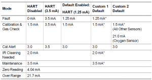
The range for the changeable AO settings is 0.000 mA to 3.750 mA. The change step is 0.025 mA. Please note the HARTcommunication may not work reliably if the current level is set to below 1.25 mA.
4.4.2 Relay Zone – Horn Mode
Horn mode is designed to allow local acknowledgment of a relay-triggered horn, while the alarm state is still present. All alarms on both sensors trigger both relays, however the second relay can be acknowledged over Modbus/Bluetooth/HART.
4.4.3 Unit Device ID/Tag
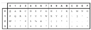
This is device tag/name used to identify the unit during HART and Bluetooth communication. Default is “GM_S5K_0 “. Users can change this string to any characters from the following character set. The string length is limited to eight characters.
4.4.4 Alarm Direction
Relays can be triggered by an alarm threshold as gas readings increase or decrease. Most applications require increasing alarm thresholds, except for Oxygen monitoring, which is most often a decreasing alarm. The default alarm direction for Oxygen sensor is decreasing, or downward. The default alarm direction for all other sensors is increasing, or upward. The alarm direction can be set to increasing/upward or decreasing/downward. Alarm direction for Oxygen sensor can be changed through UI directly, or through Modbus/Bluetooth/HART. The alarm direction setting for all other sensors can only be changed through Modbus/Bluetooth/HART.
4.4.5 Alarm Enable/Disable
Users can disable alarms by changing this setting. Default value is Enabled for this setting. Users can change this setting to Enabled or Disabled.
5 Calibration
Calibration is the process of applying a known quantity of gas to the transmitter so that the transmitter can adjust the precision and accuracy of the measurements made in normal operating mode. This process ensures that gas measurements are as accurate as possible.
Calibration Warnings – Read before CalibratingAlthough S5000 sensors are factory calibrated, another calibration is recommended once the unit is installed in its final environmental destination.
WARNING!
Use zero gas when zeroing the S5000 transmitter if there is any possibility of background gas. Otherwise, improper calibration could occur. Use zero gas when zeroing IR700 sensors. Air contains CO2 and cannot be used. Nitrogen is recommended as a zero gas. Otherwise, improper calibration could occur. For optimal sensor performance, allow sensor to acclimate to application conditions for 24 hours before performing an initial calibration. Perform calibrations 24 hours after initial start up and at a frequency identified in 5.2 Calibration Frequency and 5.3 Calibration Frequency for XCell Sensors with TruCal (H2S & CO only) . XCell Sensors with TruCal (CO & H2S) with Calibration Alert enabled provide an indication for “Calibration Recommended” and “Calibration Required’. When either indication is provided by the device, calibrate the sensor.
Failure to follow this warning can result in serious personal injury or death.
5.1 Calibration EquipmentA gas cylinder with a known concentration of gas appropriate for the range of measurement is needed. Sensors come with preset span gas values appropriate for the measurement range.All of the calibration hardware for XCell sensors is included in a convenient calibration kit. It includes a carrying case that can fit two cylinders, a regulator, tubing, and any other accessories required for each sensor type. The calibration kit can be ordered separately or as a single line item with the gas cylinder. See Table 16 for a complete list of calibration cylindersand kits. The Digital Toxic, Oxygen, and Catalytic Bead sensors share the same sensor body design and use the same calibration hardware. The calibration kit for IR400 sensors is ordered separately (P/N 1400270-2) and contains a regulator, tubing, and other calibration accessories specific to the IR400. The calibration kit for IR700 sensors is P/N 31478-1.Passive sensors use different calibration hardware to accommodate the different sized sensor housing. Passive MOS sensors can be calibrated with either calibration gas cylinders or ampules. See Table 16 for P/N details.The sensor guard and rubber calibration cap should be removed after calibration.
Table 16 Calibration Kits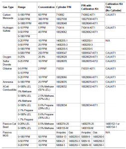
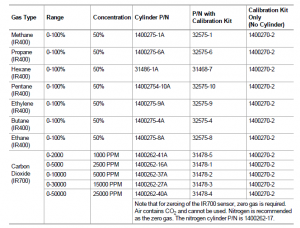
Flow Rates:CALKIT1 and 1400270-2 = 1 liter/min1400152-1 and 1400154-1 = 0.5 liter/minCALKIT2 = 0.25 liter/min
5.2 Calibration Frequency
The frequency of calibration gas testing depends on the operating time, chemical exposure, and type of sensor. Especially in new installations or applications, it is recommended that the first sensors be calibrated more often to establish the sensor performance in this particular environment. For this, record the “as found” and “as left” values and track the percent adjustment over time. Then, gradually extend calibration intervals until the percent adjustment is greater than the expected accuracy of the sensor.
5.3 Calibration Frequency for XCell Sensors with TruCal (H2S & CO only)
WARNING!
Certain conditions may prevent the performance of Diffusion Supervision and/or TruCal testing. If such a condition persists for 90 days, the XCell sensor with TruCal will recommend a calibration which is communicated through the transmitter display and LEDs. When Calibration Alert is enabled, the milli-amp signal output will also be driven to calibration alertoutput. Perform a calibration when the device recommends it.
Failure to follow this warning can result in serious personal injury or death.
5.3.1 XCell Sensor with TruCal and Diffusion Supervision (CO&H2S Only)Sensors with TruCal technology will adjust sensitivity without any manual intervention or calibration, unless called for by the sensor. If the adjusted sensitivity from TruCal deviates too far from the last gas calibration sensitivity, the sensor will recommend or, in extreme cases, require a calibration. When a calibration is recommended, the transmitter LED status indicators slowly pulse green. Users can also enable a Calibration Alert function that will send a milli-amp signal on the analog output to the control room when a calibration is recommended. When a calibration is required, the status LEDs will flash yellow and the transmitter will go into a Calibration Required Fault. With Diffusion Supervision and Calibration Alert enabled, the time between scheduled calibrations can be extended to 24 Months. If calibration alert and/or diffusion supervision are disabled follow the calibration frequency recommendation set forth in5.3.2 XCell Sensor with TruCal without Diffusion Supervision (CO&H2S Only).
5.3.2 XCell Sensor with TruCal without Diffusion Supervision (CO&H2S Only)Sensors with TruCal technology will adjust sensitivity without any manual intervention or calibration, unless called for by the sensor. If the adjusted sensitivity from TruCal deviates too far from the last gas calibration sensitivity, the sensor will recommend or, in extreme cases, require a calibration. When a calibration is recommended, the transmitter LED status indicators slowly pulse green. Users can also enable a Calibration Alert function that will send a milli-amp signal on the analog output to the control room when a calibration is recommended. When a calibration is required, the status LEDs will flash yellow and the transmitter will go into a Calibration Required Fault. Without Diffusion Supervision, regular calibration of the sensor must still be conducted to confirm the sensor inlet is not obstructed. Actual TruCal sensor performance will depend on the application, background gas exposure, and environment. To validateXCell sensors with TruCal, it is recommended that users follow their regular calibration cycle and record the “as found” and “as left” values, tracking the percent adjustment over time. Once a baseline is established, the calibration intervals can be extended until the percent adjustment is greater than the expected accuracy of the sensor.
5.4 Calibration Types: Zero vs. SpanThere are two types of calibration; zero and span calibration. The zero calibration resets the baseline level reading to zero. If the target gas is suspected to be occasionally present, it isbest to also use a zero gas cylinder during the zero calibration. If the target gas is not present in the atmosphere, an additional calibration cylinder is not required. The span calibration is a process that involves first zeroing the baseline reading, then applying a known amount of target gas so that the accuracy and precision of the transmitter can be adjusted to the known value. The known concentration of gas is called a “Span Value” because it represents the span or reach of the calibration curve from zero to that value.
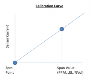
The Sensor Span Value (i.e. Cal Level) in the device menu should be the same as the concentration listed on the calibration gas cylinder.
5.5 How to Zero Calibrate XCell and IR Sensors
NOTICE If a password is enabled, you will not be able to proceed with the calibration without the password.
To abort, press the EZ touch button or apply magnet over GM logo before applying target gas. In the event that a calibration cannot be completed, the user can acknowledge the FAIL by pressing the EZ touch button or applying magnet to the GMI logo area until “Reset” is displayed and then release. The unit will revert to the settings of the last successful calibration.
WARNING!
The regulator used with the zero gas cylinders should not be the same as the regulator used for the target gas. The zero gas regulator can be contaminated with the target gas over time, and thus raise the detection baseline and make the sensor less sensitive to the target gas.
Failure to follow this warning can result in serious personal injury or death.
If there is no target gas in the atmosphere around the sensor, using a zero gas cylinder is optional. Note that, since air contains CO2, a zero gas cylinder is required for zeroing an IR 700 sensor. For IR700 sensors, nitrogen is recommended as the zero gas.
- Screw the sensor guard to the bottom of the sensor housing.
- Place the green calibration cap over the sensor guard inlet so that it is flush with the bottom of the sensor guard and completely covers the sensor guard inlet.
- Attach the tubing to the plastic stem protruding through the green calibration cap.
- Screw the regulator onto the top of the zero gas cylinder.If a password is enabled, you will need to enter it to access the menu system.NOTICE If the calibration cap cannot be used (such as for a remote sensor application), ambient wind conditions must be minimized during calibration to avoid a calibration with increased sensitivity.
- Press EZ touch until Zero is displayed, and release.
- Once the screen displays Zero in Progress, turn on zero gas flow by turning knob on the regulator.
- Wait while the device displays Zero in Progress.
- Once the zero calibration is complete, a Zero PASS or FAIL is displayed. If PASS displays, the procedure is complete. If FAIL displays, the procedure was unsuccessful (see 6.5 Troubleshooting).
- Remove the zero calibration equipment from the device including the sensor guard and calibration cap.
Sensors with TruCal and have Diffusion Supervision enabled can go into Diffusion Supervision Fault if the green Calibration Cap is left on after completing a zero calibration.
WARNING!
The green Calibration Cap must be removed from the sensor after a zero calibration. Failure to do so could restrict gas flowto the sensor and result in erroneously low readings.
Failure to follow this warning can result in serious personal injury or death.
To abort, press the EZ touch button or apply magnet over GM logo before applying target gas. In the event that a calibration cannot be completed, the user can acknowledge the FAIL by pressing the EZ touch button or applying magnet to the GMI logo area until “Reset” is displayed and then release. The device will revert to the settings of the last successful calibration.If it is suspected that gases are present, it will be necessary to purge the sensor environment with zero air.
To calibrate the sensor:
- Attach a regulator to the zero gas cylinder (if using) and the calibration cylinder.
- Attach the plastic sensor guard to the bottom of the sensor housing if not already installed.
- Place the green calibration cap over the sensor guard inlet so that it is flush with the bottom of the sensor guard and completely covers the sensor guard inlet.
- Attach the tubing to the plastic stem protruding through the green calibration cap.
- Push the other end of the tubing over the zero cylinder regulator. Ensure the tubing completely covers the gas outlet.
- Press EZ touch until Calibration is displayed, and release.If a password is enabled, you will need to enter it to access the menu system.NOTICEIf the calibration cap cannot be used (such as for a remote sensor application), ambient wind conditions must be minimizedduring calibration to avoid a calibration with increased sensitivity.
- Select Sensor #1 or Sensor #2, and then select “Finished?” to start the calibration process.
- Once the screen displays Zero in Progress, turn on zero gas flow by turning knob on the regulator (if using).
- Wait while the device displays Zeroing.
- Once the Zero Calibration is complete, remove the tubing from the sensor guard inlet.
- The display will show Apply Gas. Attach tubing for calibration gas and turn on the regulator Display will show “Calibration in Progress”. “Calibration Complete Remove Gas” will show when span is complete.If “PASS” displays, the procedure is complete.If “FAIL” displays, the procedure was unsuccessful. See 6.5 Troubleshooting.
- Remove the calibration equipment from the device, including the sensor guard and calibration cap.
Sensors with TruCal and have Diffusion Supervision enabled can go into Diffusion Supervision Fault if the green Calibration Cap is left on after completing a calibration.
5.7 How to Calibrate an Oxygen XCell Sensor
An oxygen span gas cylinder is not needed if the sensor is in an area that maintains ambient air conditions. Follow the same process for XCell sensors as described in 5.6 How to Calibrate XCell Sensors. When the display prompts “Apply Span Gas”, simply allow the countdown to occur without applying gas. If the sensor is located in an area of normally low or enriched oxygen, then a 20.8% oxygen sample must be applied.
5.8 How to Calibrate an IR Sensor
A full span calibration is not required for the IR Sensors. Any degradation of the sensor’s performance is associated with slight drifts in its zero response. Restoring the sensor’s zero is typically sufficient. Note that for zeroing of the IR700 sensor, zero gas is required. Air contains CO2 and cannot be used. Nitrogen is recommended as the zero gas. The nitrogencylinder P/N is 1400262-17.See 5.5 How to Zero Calibrate XCell and IR Sensors for zero calibration instructions.If a full calibration of the IR Sensor is required, a larger calibration cap is used and covers the entire sensor guard during calibration. The calibration cap must be removed after completing the zeroing and/or spanning procedure
NOTICEIf the calibration cap cannot be used (such as for a remote sensor application), ambient wind conditions must be minimizedduring calibration to avoid a calibration with increased sensitivity.
5.9 How to Calibrate a Passive Sensor (Catalytic Bead or MOS)
The sensor calibration cup must be removed from the sensor after calibration. Failure to do so could restrict gas flow to the sensor and result in erroneously low readingsFailure to follow this warning can result in serious personal injury or death.
If a password is enabled, you will need to enter it to access the menu system.If the sensor is fitted with a sensor guard, calibration must be performed with the sensor guard in place.If it is suspected that gases are present, it will be necessary to purge the sensor environment with zero air.
To calibrate sensor:
- Attach a regulator to the zero air cylinder (if using) and the calibration cylinder.
- Attach the plastic calibration cup (P/N 1400152-1 or 1400154) to the bottom of the sensor if not already installed.
- Attach the tubing to the plastic stem protruding through the calibration cup.
- Push the other end of the tubing over the zero cylinder regulator. Ensure the tubing completely covers the gas outlet.
- Press EZ touch until Calibration is displayed, and release the touch.
- Turn on zero gas flow by turning knob on the regulator (if using).
- Unit will start flashing the sensor life. Tap the EZ Touch if you want to reset the sensor life.
- Wait while the device displays “Zero in Progress”.
- Once the Zero Calibration is complete, remove the tubing from the calibration cup inlet.
- The display will show “Apply Gas”. Attach tubing for calibration gas and turn on the regulator.
- Display will show “Calibration in Progress”.
- “Calibration Complete. Remove Gas” will show when span is complete.
- Turn off the calibration gas regulator. Remove the calibration equipment from the device, including the calibration cup.Unit will return to normal operation.If “Cal Fail” and fault code displayed, the procedure was unsuccessful. See 6.5 Troubleshooting.
5.10 XCell Catalytic Bead Failsafe
Catalytic bead sensors require the presence of oxygen in order to sense combustible gas. In the event of very large combustible gas leaks that exceed 100 % LEL, enough oxygen can be displaced so that the sensor’s response to gas is no longer proportional to the calibration profile. The XCell catalytic bead has a locking fail safe mechanism that prevents thefalse reporting of a safe condition while the % LEL concentration is still above 100 % LEL. When the gas concentration exceeds 100 % LEL, the sensor will go into LOC over range.To clear the LOC over rage, the user needs to acknowledge and calibrate the sensor. To acknowledge LOC over range, press the EZ touch button or apply magnet to the GMI logo area until “Reset” is displayed and then release. This will allow a recalibration of the sensor to clear the LOC condition.
WARNING!
Ensure that the area has been cleared of gas before acknowledging the LOC Over Range and recalibrating the sensor.Failure to follow this warning can result in serious personal injury or death.
5.11 Calibration Confirmation
The S5000 Series Monitor records the date of the last successful calibration. This date can then be displayed via the Status Menu.
6 Maintenance
WARNING!
Use only genuine MSA replacement parts when performing any maintenance procedures provided in this manual. Failure to do so may seriously impair sensor and gas monitoring performance, alter flameproof/explosionproof characteristics or void agency approvals. Failure to follow this warning could cause the product to fail to perform as designed and persons whorely on this product for their safety could sustain serious personal injury or loss of life. Repair or alteration of the S5000 Gas Monitor, beyond the scope of the maintenance procedures provided in this manual or by anyone other than authorized MSA service personnel, could cause the product to fail to perform as designed and persons who rely on this product for their safety could sustain serious personal injury or loss of life. The S5000 Gas Monitor is constantly performing a self-check. When a problem is found, it displays the appropriate errormessage (see 6.5 Troubleshooting). When a critical error is detected within the device, the 4-20 mA output signal goes to a fault condition of 0 mA, 1.25 mA, 3.5 mA or user defined level.
6.1 IR Sensor Cleaning Procedure
The presence of particulate matter, oil films, liquid water, or the residue from water drops on the two monitor windows can adversely affect its performance. The sensor guard is designed to prevent foreign solids or liquids from reaching the monitor’s optical system. Additionally, heating elements are incorporated into the device to prevent water condensation.Under severe conditions, however, some material may collect on these surfaces and it may be necessary to occasionally check and clean the windows. While both windows are made of a highly durable material that is not easily scratched, avoid excessive pressure when cleaning them. Clean, cotton-tipped applicators are the most convenient tool to remove material collected on the windows.
- Remove the sensor guard.
- Use a dry applicator or one moistened with distilled water to wipe the window and remove dust.
- Use an additional clean, dry applicator to remove any residual water.
- Use an applicator moistened with isopropyl alcohol to remove heavy deposits of solids, liquids or oil films. Clean the window again with a second applicator moistened with distilled water; then, dry the window with a final applicator. Avoid using excessive amounts of water or alcohol in the cleaning procedure, and inspect the window to ensure that the entire surface is clean.
- The device will go into a “Cleaning required” fault with an analog output of 2.0 mA when cleaning is needed. The S5000 analog output may go down to 1.25 mA while the optical path is blocked, and display will indicate “Beam Block”.While in “Beam Block” fault, the sensor will not respond to the presence of gas
- When cleaning is done and the objects are removed from the sensor window, the device returns to normal operation. If water or isopropyl alcohol was used, allow the device to operate for 15 minutes to completely dry before replacing the sensor guard continuing to monitor for combustible gas.
- Replace the sensor guard.When the cleaning process is complete, be sure to remove all objects from the light path. It is recommended to check the sensor’s response to zero and calibration gas after cleaning.
WARNING!
Do not place foreign objects in the sensor’s analytical region (except per the “S5000 IR Sensor Cleaning Procedure” as described above); otherwise, the infrared beam can be partially blocked, causing the sensor to generate false readings. All objects must be removed from the sensor’s analytical region for it to function properly.Failure to follow this warning can result in serious personal injury or death.
6.2 Replacing an XCell Sensor
The only routine maintenance item is the sensor, which has a limited lifetime. The S5000 sensors with TruCal technology will indicate when the sensor is near end of life through the Status Menu. When the Sensor Life & Health status is “Fair”, there is approximately 2 month time frame to replace the sensor before it will no longer function. Actual time between “Fair”status and sensor end of life depends on exact environmental conditions. When a TruCal sensor is no longer capable of sensing it will go into fault and LEDs will flash yellow. It is good practice to obtain a replacement sensor before the sensor within the unit becomes inoperative. There is no need to open the main enclosure. Simply unscrew the sensor assembly located on the bottom of the main assembly.
WARNING!
- Do not disassemble the sensor assembly. The sensing element inside may contain hazardous material.
- Handle the sensor carefully; the electrochemical version is a sealed unit which contains a corrosive electrolyte.
- Any leaked electrolyte that comes in contact with skin, eyes or clothes can cause burns.
- If any contact with the electrolyte does occur, immediately rinse with a large quantity of water. On contact with the eyes, rinse thoroughly with water for 15 minutes and consult a doctor.
- Do not install a leaking sensor in the sensing head assembly.
- A leaking sensor must be disposed of in accordance with local, state and federal laws.
- As part of the product certification, it was verified that optional communication functions of this gas detection instrument while operating at the maximum transaction rate do not adversely affect the gas detection operation and functions of the instrument. The product certification, however, does not include or imply approval of the SafeSwap feature, communications protocol or functions provided by the software of this instrument or of the communications apparatus and software connected to this instrument.
- Follow the warnings below when removing or replacing sensors. Reference Figure 3 for component overview.– Never remove or replace a Sensor Body Assembly or an IR Sensor while under power or when explosive hazards are present.– Confirm that the area is free of explosive hazards before removing or replacing an XCell Sensor under power.– To remove an XCell Sensor, unscrew XCell Sensor three full turns, wait 10 seconds, and then remove the XCell Sensor completely.
Failure to follow this warning can result in serious personal injury or death.
Identify the sensor assembly needed via the A-5K-SENS code on the interior sensor label and obtain the appropriate sensor assembly; replace sensor assembly. Figure 33 Removing the XCell Sensor

Figure 34 Digital Sensor – Position of Labels
Alarm set points, span value, full scale limit and alarm direction will not change when replacing a sensor with the same gas type. Alarm set points, span value, full scale limit and alarm direction will change to the new sensor’ settings when replacing a sensor with a different gas type.
The S5000 Gas Monitor is shipped with the Sensor Swap Delay enabled. IF enabled, the 4-20 mA output signal goes to 3.5 mA and the FAULT relay will hold off a fault indication for 2 minutes. This setting allows the operator to exchange sensor modules without a FAULT indication.It is recommended that all other maintenance be performed at an MSA factory-authorized service center.
6.3 Clearing a Blockage
If using a Digital Sensor with Diffusion Supervision, and if the Diffusion Supervision feature has been enabled in the Sensor Settings, the sensor will notify the user if it detects foreign material obstructing the sintered metal frit where gas would normally enter the sensor (see Frit Location). When this condition is detected, the transmitter will go into fault and show “Diffusion Supervision Fault” on the display. Follow these recommended steps to attempt to clear this fault:
- Inspect and clear the sensor inlet and frit.
- Inspect and clear any accessories attached to the sensor.
- Ensure Sensor is fully mated to the Sensor Body Assembly.
- Attempt to recalibrate the Sensor.
- Disable Diffusion Supervision or replace the Sensor.First, with the sensor still installed, visually inspect the sensor to see if any objects are covering the gas inlet and remove them. Example objects may include tape or the green Calibration Cap. Next, check to make sure that there is no foreign material stuck to the frit. If any material is found, gently remove it while considering any hazards that may arise from suchan action, like the accumulation of a static charge, and taking the necessary steps to avoid them. Take care to ensure that the frit is not damaged during the cleaning process. DO NOT use water or liquids to try to clean the frit. The frit acts like a sponge and will retain liquids, which will keep the gas path blocked.

WARNING!
The sensor relies on the frit as a part of its Flameproof/Explosionproof approval. If the frit is damaged while attempting to clean it, immediately remove power from the device. Ensure the area is free of a hazardous atmosphere, then follow all steps as outlined in this manual to properly replace the sensor. Failure to follow this warning can result in serious personal injury or death.
If no material is visible, the frit may still be blocked by a liquid which has absorbed into the frit. Once absorbed, liquids are very difficult to remove. For these situations, relying on natural evaporation is recommended. Due to the time it can take for liquids to evaporate sufficiently from the frit, users may want to consider swapping out the affected sensor with one that isknown to be clear. Placing absorbent material against the outer surface of the frit can help accelerate this process.If a sensor is in Diffusion Supervision Fault, the device will still allow the user to attempt to calibrate the sensor. In the rare event that a sensor calibration is successful, but the Diffusion Supervision system continues to detect a blockage in the gas path, the Diffusion Supervision Fault will return in approximately 24 hours. In this scenario, there is likely an environmental factor affecting the Diffusion Supervision detection. Provided the sensor can successfully calibrate, the sensor is still capable of detecting gas. To prevent the Diffusion Supervision Fault from reoccurring, a user can either disable Diffusion Supervision in the Sensor Settings (see 4.2.2 Sensor Setup) or replace the sensor.
6.4 Replacing a Passive Sensor (Cat Bead or MOS)
When the passive Catalytic Bead or MOS sensor is damaged or gradually losing sensitivity and eventually fails to respond to gas adequately or fails to pass calibration, the sensor needs to be replaced. The mounting threads of the sensor head may require lubrication. Grease must not be used. As an alternate, PTFE (Teflon) tape may be used on sensor threads.
To replace the passive sensors:
- Declassify the area and make sure there is no hazardous gas/vapor present.
- Power down the S5000 transmitter.
- Unscrew the lid.
- Remove the User Interface Module.
- Refer to the sensor wiring diagram label inside the S5000 transmitter to locate the sensor connector and unplug it from the transmitter.
- Unscrew the sensor head until it is totally off. Guide the sensor wires so they will not get caught by the internal parts of the S5000 while sensor head is turning.
- Guide the connector and wires of the new sensor head through the conduit entry for sensor. Do not plug in the sensor connector at this time.
- Screw in the new sensor head. Guide the sensor wires so they will not get caught by the internal parts of the S5000 while sensor head is turning.
- Verify the sensor connector wiring against the wiring diagram.
- Plug in the connector to the indicated header and make sure they are mated correctly.
6.5 Troubleshooting
Table 17 Troubleshooting
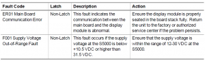
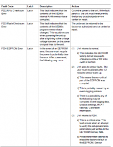
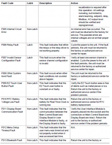

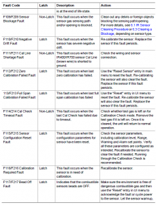
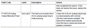
7 Ordering Information
7.1 Replacement PartsSee Table 18 for replacement sensor kits. To obtain a replacement sensor, address the order or inquiry to:General Monitors26776 Simpatica CircleLake Forest, CA 92630or call, toll-free, 1-800-446-4872.Inquiries can also be e-mailed to
WARNING!
Use only genuine MSA replacement parts when performing any maintenance procedures provided in this manual. Failure to do so may seriously impair sensor and gas monitoring performance, alter flameproof/explosionproof characteristics or void agency approvals. Failure to follow this warning could cause the product to fail to perform as designed and persons whorely on this product for their safety could sustain serious personal injury or loss of life. Repair or alteration of the S5000 Gas Monitor, beyond the scope of the maintenance procedures provided in this manual or by anyone other than authorized MSA service personnel, could cause the product to fail to perform as designed and persons who rely on this product for their safety could sustain serious personal injury or loss of life.Failure to follow these warnings can result in serious personal injury or death.
Table 18 Replacement Parts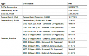
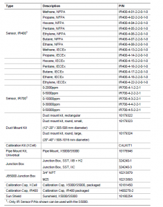 For position of labels, see 2.11 Label OverviewThe following accessories have been validated for use when installed in accordance with the instructions in this manual:
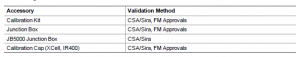
8 Appendix: Specifications
Table 19 Digital Sensor Specifications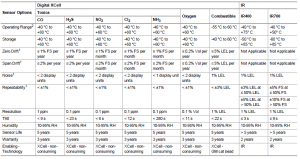
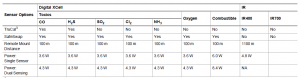
1- Typical response at room temperature2- S5000 transmitter has an operating temperature range of -55°C to +75°C.3- Adaptive Environmental Compensation (AEC) and Diffusion Supervision (DS) will remain active between -20°C and +60°C.4- These specifications are internally generated data. See the FM Approval section for data that conforms to the FM certification in accordance to FM 6340.
Table 20 Passive Sensor Specifications
1- Typical response at room temperature.2- S5000 transmitter has an operating temperature range of -55°C to +75°C.3- Adaptive Environmental Compensation (AEC) and Diffusion Supervision (DS) will remain activebetween -20°C and +60°C.4- These specifications are internally generated data. See the FM Approval section for data that conformsto the FM certification in accordance to FM 6340.
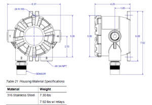
9 Appendix: General Certification Information
The S5000 Transmitter, S5000 Junction Box, and Digital Sensor have the following certifications/approvals: ATEX, IECEx, CSA, FM,INMETRO, DNV·GL Type Approval. They also comply to the EMC, Radio Equipment and Marine Equipment Directives. The S5000 Transmitter and Junction Box have a Type 4X and IP66 environment rating.
S5000 Transmitter, Junction Box, and JB5000 Junction Box
U.S. Division Hazardous Locations as defined by the NECClass I, Division 1, Groups A, B, C, D; T5/T6*Class I, Division 2, Groups A, B, C, D; T4/T6*Class II, Division 1,2 Groups E, F, G; Class III, Division 1,2; T6 (T5 under FM Approval)NOTE: See CSA Certificate for detailed certification information including possiblelimitations to the above information. FM Approval does not include Zone classified locations.*Applicable to S5000 Junction Box onlyU.S. Zone Hazardous Locations as defined by the NECClass I, Zone 1, AEx db IIB+H2 T5/T6* GbClass I, Zone 2, AEx nA nC** IIC T4/T6* GcZone 21, AEx tb IIIC T85°C DbNOTE: See CSA Certificate for detailed certification information including possiblelimitations to the above information. FM Approval does not include Zone classified locations.*Applicable to S5000 Junction Box only**nC not applicable to S5000 Junction BoxCanadian Division Hazardous Locations as defined by the CECClass I, Division 1, Groups A**, B, C, D; T5/T6*Class I, Division 2, Groups A, B, C, D; T4/T6*Class II, Division 1,2 Groups E, F, G; Class III, Division 1,2; T6NOTE: See CSA Certificate for detailed certification information including possiblelimitations to the above information.*Applicable to S5000 Junction Box only**Applicable for cemented window covers onlyCanadian Zone Hazardous Locations as defined by the CECEx db IIB+H2 T5/T6* GbEx nA nC** IIC T4/T6* GcEx tb IIIC T85°C DbNOTE: See CSA Certificate for detailed certification information including possiblelimitations to the above information. *Applicable to S5000 Junction Box only
**nC not applicable to S5000 Junction BoxATEX/IECEx/INMETRO Hazardous Locations(Sira 17ATEX1048X, Sira 17ATEX4052X, IECEx SIR 17.0016X, NCC 18.0097X)Ex db IIB+H2 T5/T6* GbEx nA nC** IIC T4/T6* GcEx tb IIIC T85°C DbNOTE: See ATEX/IECEx Certificates for detailed certification information includingpossible limitations to the above information.*Applicable to S5000 Junction Box only**nC not applicable to S5000 Junction BoxNOTE: For configurations incorporating cemented covers, IIB+H2 is replaced by IIC.
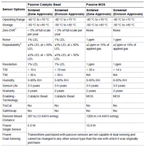

WARNING!
Some toxic gases are provided in a fritless sensor housing. The fritless sensor housing is labeled as Div 2 or Zone 2 and is approved for Div 2 or Zone 2 installations only. The protection method is Nonincendive or Type n respectively. Ensure all components are approved for the wiring method being used and in accordance with the National Electric Code of thecountry of use, any applicable local regulations, and this manual.Failure to follow this warning can result in serious personal injury or death.

Figure 37 Digital Sensor for Div 1 & 2, Zone 1 & 2 (Left) vs Digital Sensor for Div 2, Zone 2 only (right)
IR SensorSee the applicable IR Sensor Instruction Manual (IR400 Sensor: P/N MANIR400; IR700 Sensor: P/N MANIR700), orcertificates Sira 07ATEX1253 and IECEx SIR 07.0080.
Passive SensorsSee certificates Sira 00ATEX1039U and IECEx SIR 07.0007U
FM ApprovalThis approval does not include or imply approval of apparatus to which the subject instrument may be connected. In order to maintain an FM Approved system, the apparatus to which this instrument is connected, must also be approved by FM Approvals. As part of this approval, it was verified that optional communication functions of this gas detection instrumentwhile operating at the maximum transaction rate do not adversely affect the gas detection operation and functions of the instrument. This approval, however, does not include or imply approval of the communications protocol or functions provided by the software of this instrument or of the communications apparatus or software connected to this instrument. The S5000 Transmitter, S5000 Junction Box, Digital Sensors (H2S, 500 ppm H2S, CO, O2), and Passive MOS H2S sensors also have FM Performance Approval for use in ordinary (nonhazardous) or hazardous locations.
The following information shall be noted for FM Approved configurations:
- The FM Approved Digital Sensors have an IP65 and TYPE 3X environmental rating, however if water is splashed onto the frit (also referred to as a flame arrestor), the sensor may not be able to detect gas for a period of up to 12 minutes. If water is splashed onto this element, use a cloth or paper towel to dab the frit in order to absorb any excess water.
- The FM Approval requires that password protection for Bluetooth be enabled.
- The Digital Sensor (O2) is not to be used in environments containing 5% (v/v) or more of carbon dioxide.
- The Digital Sensor (O2) is unaffected by air velocities of up to 5 m/s.
- The response and recovery times for the Digital Sensor (H2S, 500 ppm H2S, CO, O2) and Passive MOS sensor are asfollows:
- The operating and storage temperature ranges are as follows:
- The Accuracy spec. is as follows:
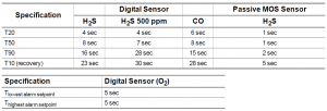
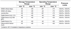
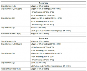
WARNING!
- Read and understand all instructions, warnings and cautions prior to installation of any components of this system.
- Open circuit before removing cover.
- Sealing requirements:– Aluminum S5000 transmitter and Junction Box: A seal shall be installed within 18 in (450 mm) of the enclosure.– Stainless Steel S5000 transmitter, Junction Box, and JB5000: Seal is not required.– Stainless Steel S5000 transmitter and Junction Box with FM Approval: A seal shall be installed within 18 inches (450mm) of the enclosure.
- Transmitter and Junction Box (cemented or non-cemented covers) – do not open when energized or when an explosive atmosphere is present
- Transmitter and Junction Box (cemented or non-cemented covers) – live parts behind cover, open circuit before removing cover – do not contact.
- Transmitter and Junction Box (cemented or non-cemented covers) – potential electrostatic charging hazard. Clean equipment only with damp cloth. Failure to follow this warning can result in severe personal injury or loss of life.
- Digital Sensor – do not separate when an explosive atmosphere is present.
- No ingress protections claims are made for combustible gas detection performance.
- For safety reasons this equipment must be operated and serviced by qualified personnel only. Do not operate this equipment until after the instruction manual is read and understood for proper installation and operation.
- High off-scale reading may indicate explosive concentration.
- Wiring to or from this device, which enters or leaves the system enclosure, must utilize wiring methods suitable for Class I, Division 2/Zone 2 hazardous locations, as appropriate for the installation.
- Explosion hazard: Do not connect or disconnect when energized.
- Use cable with insulation rated at least 24 °C above the surrounding ambient.
- As part of this Approval, it was verified that optional communication functions of this gas detection instrument while operating at the maximum transaction rate do not adversely affect the gas detection operation and functions of the instrument. This Approval, however, does not include or imply Approval of the “SafeSwap” feature, communications protocol or functions provided by the software of this instrument or of the communications apparatus or softwareconnected to this instrument.
- Use of some accessories are not covered under the performance approval. Contact General Monitors for details.
Specific Conditions of Use S5000 Transmitter
- Under certain extreme circumstances, the non-metallic parts incorporated in the enclosure of this equipment may generate an ignition-capable level of electrostatic charge. Therefore, the equipment shall only be cleaned with a damp cloth.
- This fixed equipment apparatus is exclusively designed for field mounting in the vertical orientation with restrictions placed around the conduit entry locations permitted for connection of both the Digital Sensor and IR Sensor. The equipment is subject to the installation and orientation requirements defined in the product manual.
- The flameproof joints shall not be repaired.
- The S5000 Gas Monitor fixed gas detection system complies with EN 50271 (clause 4.8, safety integrity assessmentexcluded from the assessment).
S5000 Junction Box
Under certain extreme circumstances, the non-metallic parts incorporated in the enclosure of this equipment may generate an ignition-capable level of electrostatic charge. Therefore, the equipment shall only be cleaned with a damp cloth.
- The flameproof joints shall not be repaired.
- The S5000 Gas Monitor fixed gas detection system complies with EN 50271 (clause 4.8, safety integrity assessment excluded from the assessment).
Digital Sensor
- Under certain extreme circumstances, the non-metallic parts incorporated in the enclosure of this equipment may generate an ignition-capable level of electrostatic charge. Therefore, the equipment shall only be cleaned with a damp cloth.
- The flameproof joints shall not be repaired.
- If the sensor is uninstalled, the equipment instruction manual shall be referenced prior to reinstalling.
- The Digital Sensor is provided with a ¾“ NPT thread and shall only be connected to a suitably certified enclosure. The installation to the certified enclosure shall be with five fully engaged threads, tightened wrench-tight.
- The Digital Sensor shall be connected directly to a suitably certified junction box or instrument for the hazardous area of installation and thereby provide Ex protection for the flying lead connections.
- For combustible gas detection performance applications, the appropriate Digital Sensor model number shall only be used to construct the S5000 Gas Monitor fixed gas detection system; mounted onto either the S5000 transmitter or S5000 Junction Box enclosures and receive power and control from the transmitter.
- The Ingress Protection rating is exclusively based upon the installation instruction for orientation specified in the operating manual.
- The Digital Sensor shall only be installed for external connection to suitably certified equipment (transmitters) providing transient protection set at a maximum transient overvoltage of 119 V (140% of 85 Vpeak).
- Not performance approved for Class II, Class III, Zone 21. The Digital Sensor may become clogged and not detect gas or warn user of inability to detect gas. Regularly visually inspect the sensor and apply gas to ensure a clear gas path to the sensor if there is potential that blockage has occurred. Conditions that may lead to blockage, including but not limited to snow, ice, water, dirt, dust, or insects necessitate more frequent inspections.
Failure to follow these warnings can result in serious personal injury or death.
10 Appendix: HART Specific Information
The S5000 Gas Monitor is available with an optional HART (Highway Addressable Remote Transducer) output communications protocol. With this option, the S5000 complies with HART Protocol Revision 7 and uses the 16-bit manufacturer and device codes. This document specifies all the device specific features and documents HART Protocol implementation details (e.g., the Engineering Unit Codes supported). These specifications assume the reader is somewhat familiar with HART Protocol requirements and terminology. This specification is a technical reference for HART-capable HOST Application Developers, System Integrators and knowledgeable End Users. It also provides functional specifications (e.g., commands, enumerations and performance requirements) used during Field Device deployment, maintenance, testing, and operations. It is recommended that the 4- 20 mA output be the primary gas monitoring signal. The HART signal can be the secondary method.
Table 22 Device Identification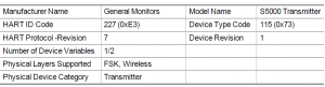
The 3.5 mA version of the IR400 is not compatible with the S5000
Read More About This Manual & Download PDF:
General Monitors S5000 Gas Monitor User Manual – General Monitors S5000 Gas Monitor User Manual –
[xyz-ips snippet=”download-snippet”]