msi H410M Pro Motherboard
| Thank you for purchasing the MSI® H410M PRO/ H410M-A PRO/ H410M PRO-VH motherboard. This User Guide gives information about board layout, component overview, BIOS setup and software installation. |
Safety Information
- The components included in this package are prone to damage from electrostatic discharge (ESD). Please adhere to the following instructions to ensure successful computer assembly.
- Ensure that all components are securely connected. Loose connections may cause the computer to not recognize a component or fail to start.
- Hold the motherboard by the edges to avoid touching sensitive components.
- It is recommended to wear an electrostatic discharge (ESD) wrist strap when handling the motherboard to prevent electrostatic damage. If an ESD wrist strap is not available, discharge yourself of static electricity by touching another metal object before handling the motherboard.
- Store the motherboard in an electrostatic shielding container or on an anti static pad whenever the motherboard is not installed.
- Before turning on the computer, ensure that there are no loose screws or metal components on the motherboard or anywhere within the computer case.
- Do not boot the computer before installation is completed. This could cause permanent damage to the components as well as injury to the user.
- If you need help during any installation step, please consult a certified computer technician.
- Always turn off the power supply and unplug the power cord from the power outlet before installing or removing any computer component.
- Keep this user guide for future reference.
- Keep this motherboard away from humidity.
- Make sure that your electrical outlet provides the same voltage as is indicated on the PSU, before connecting the PSU to the electrical outlet.
- Place the power cord such a way that people can not step on it. Do not place anything over the power cord.
- All cautions and warnings on the motherboard should be noted.
- If any of the following situations arises, get the motherboard checked by service personnel:▪ Liquid has penetrated into the computer.▪ The motherboard has been exposed to moisture.▪ The motherboard does not work well or you can not get it work according to user guide.▪ The motherboard has been dropped and damaged.▪ The motherboard has obvious sign of breakage.
- Do not leave this motherboard in an environment above 60°C (140°F), it may damage the motherboard.
Specifications
| CPU | Supports 10th Gen Intel® Core™ and Pentium® Gold / Celeron® processors for LGA 1200 socket** Please go to www.intel.com for more compatibility information.* Onboard graphics output are disabled when using F SKU processors. |
| Chipset | Intel® H410 chipset |
| Memory |
* Please refer www.msi.com for more information on compatible memory. |
| Expansion Slots |
|
| Onboard Graphics |
|
|
|
| Audio | Realtek® ALC892/ ALC897 Codec
|
| LAN | 1x Intel® I219V Gigabit LAN controller |
| Storage | Intel® H410 Chipset
|
|
USB |
Intel® H410 Chipset
|
| Internal Connectors |
|
| Back Panel Connectors |
|
| I/O Controller | NUVOTON NCT5887D Controller Chip |
| Hardware Monitor |
|
| Form Factor |
|
| BIOS Features |
|
| Software |
|
| Dragon Center Features |
|

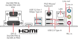
Rear I/O Panel
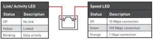
LAN Port LED Status Table
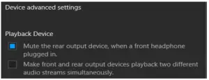
Audio 7.1-channel Configuration
To configure 7.1-channel audio, you have to connect front audio I/O module to JAUD1 connector and follow the below steps.
- Click on the Realtek HD Audio Manager > Advanced Settings to open the dialog below.

- Select Mute the rear output device, when a front headphone plugged in.
- Plug your speakers to audio jacks on rear and front I/O panel. When you plug into a device at an audio jack, a dialogue window will pop up asking you which device is current connected.
Overview of Components
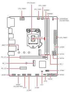
* Distance from the center of the CPU to the nearest DIMM slot.
CPU Socket
Please install the CPU into the CPU socket as shown below.
![]() Important
Important
- Always unplug the power cord from the power outlet before installing or removing the CPU.
- Please retain the CPU protective cap after installing the processor. MSI will deal with Return Merchandise Authorization (RMA) requests if only the motherboard comes with the protective cap on the CPU socket.
- When installing a CPU, always remember to install a CPU heatsink. A CPU heatsink is necessary to prevent overheating and maintain system stability.
- Confirm that the CPU heatsink has formed a tight seal with the CPU before booting your system.
- Overheating can seriously damage the CPU and motherboard. Always make sure the cooling fans work properly to protect the CPU from overheating. Be sure to apply an even layer of thermal paste (or thermal tape) between the CPU and the heatsink to enhance heat dissipation.
- Whenever the CPU is not installed, always protect the CPU socket pins by covering the socket with the plastic cap.
- If you purchased a separate CPU and heatsink/ cooler, Please refer to the documentation in the heatsink/ cooler package for more details about installation.
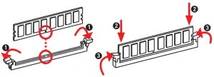
DIMM Slots
Please install the memory module into the DIMM slot as shown below.
![]() Important
Important
- Always insert memory modules in the DIMMA1 slot first.
- To ensure system stability for Dual channel mode, memory modules must be of the same type, number and density.
- Some memory modules may operate at a lower frequency than the marked value when overclocking due to the memory frequency operates dependent on its Serial Presence Detect (SPD). Go to BIOS and find the DRAM Frequency to set the memory frequency if you want to operate the memory at the marked or at a higher frequency.
- It is recommended to use a more efficient memory cooling system for full DIMMs installation or overclocking.
- The stability and compatibility of installed memory module depend on installed CPU and devices when overclocking.
- Please refer www.msi.com for more information on compatible memory.
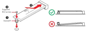
M2_1~2: M.2 Slots
Please install the M.2 device into the M.2 slot as shown below.
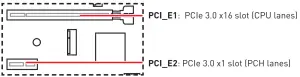
PCI_E1~2: PCIe Expansion Slots
![]() Important
Important
- When adding or removing expansion cards, always turn off the power supply and unplug the power supply power cable from the power outlet. Read the expansion card’s documentation to check for any necessary additional hardware or software changes.
- If you install a large and heavy graphics card, you need to use a tool such as MSI Gaming Series Graphics Card Bolster to support its weight to prevent deformation of the slot.
SATA1~4: SATA 6Gb/s Connectors
These connectors are SATA 6Gb/s interface ports. Each connector can connect to one SATA device.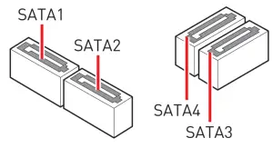
![]() Important
Important
- Please do not fold the SATA cable at a 90-degree angle. Data loss may result during transmission otherwise.
- SATA cables have identical plugs on either sides of the cable. However, it is recommended that the flat connector be connected to the motherboard for space saving purposes.
- SATA4 will be unavailable when installing M.2 SATA SSD in the M.2 slot.
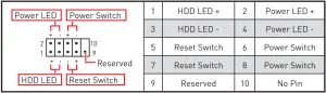
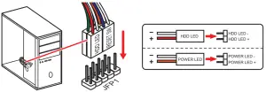
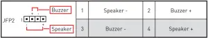
JFP1, JFP2: Front Panel Connectors
These connectors connect to the switches and LEDs on the front panel.
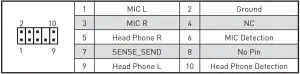
JAUD1: Front Audio Connector
This connector allow you to connect audio jacks on the front panel
ATX_PWR1, CPU_PWR1: Power Connectors
These connectors allow you to connect an ATX power supply.
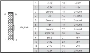
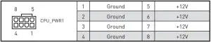
![]() ImportantMake sure that all the power cables are securely connected to a proper ATX power supply to ensure stable operation of the motherboard.
ImportantMake sure that all the power cables are securely connected to a proper ATX power supply to ensure stable operation of the motherboard.
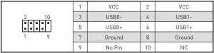
JUSB1: USB 2.0 Connector
These connectors allow you to connect USB 2.0 ports on the front panel.
![]() Important
Important
- Note that the VCC and Ground pins must be connected correctly to avoid possible damage.
- In order to recharge your iPad, iPhone and iPod through USB ports, please install MSI® DRAGON CENTER utility
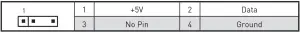
JUSB2: USB 3.2 Gen 1 5Gbps Connector
This connectors allow you to connect USB 3.2 Gen 1 5Gbps ports on the front panel.
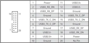
![]() ImportantNote that the Power and Ground pins must be connected correctly to avoid possible damage. Important
ImportantNote that the Power and Ground pins must be connected correctly to avoid possible damage. Important
CPU_FAN1, SYS_FAN1: Fan Connectors
PWM Mode fan connectors provide constant 12V output and adjust fan speed with speed control signal. When you plug a 3-pin (Non-PWM) fan to a fan connector in PWM mode, the fan speed will always maintain at 100%, which might create a lot of noise.
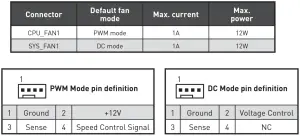
![]() ImportantYou can adjust fan speed in BIOS > Hardware Monitor.
ImportantYou can adjust fan speed in BIOS > Hardware Monitor.
JTPM1: TPM Module Connector
This connector is for TPM (Trusted Platform Module). Please refer to the TPM security platform manual for more details and usages.
JCI1: Chassis Intrusion Connector
This connector allows you to connect the chassis intrusion switch cable.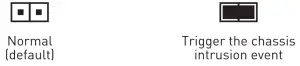
Using chassis intrusion detector
- Connect the JCI1 connector to the chassis intrusion switch/ sensor on the chassis.
- Close the chassis cover.
- Go to BIOS > SETTINGS > Security > Chassis Intrusion Configuration.
- Set Chassis Intrusion to Enabled.
- Press F10 to save and exit and then press the Enter key to select Yes.
- Once the chassis cover is opened again, a warning message will be displayed on screen when the computer is turned on.
Resetting the chassis intrusion warning
- Go to BIOS > SETTINGS > Security > Chassis Intrusion Configuration.
- Set Chassis Intrusion to Reset.
- Press F10 to save and exit and then press the Enter key to select Yes.
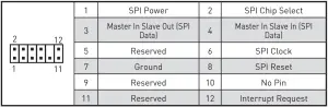
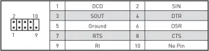
JCOM1: Serial Port Connector
This connector allows you to connect the optional serial port with bracket.
JBAT1: Clear CMOS (Reset BIOS) Jumper
There is CMOS memory onboard that is external powered from a battery located on the motherboard to save system configuration data. If you want to clear the system configuration, set the jumpers to clear the CMOS memory.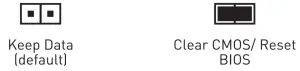
Resetting BIOS to default values
- Power off the computer and unplug the power cord.
- Use a jumper cap to short JBAT1 for about 5-10 seconds.
- Remove the jumper cap from JBAT1.
- Plug the power cord and power on the computer.
EZ Debug LED
These LEDs indicate the status of the motherboard.
![]() CPU – indicates CPU is not detected or fail.
CPU – indicates CPU is not detected or fail.![]() DRAM – indicates DRAM is not detected or fail.
DRAM – indicates DRAM is not detected or fail.![]() VGA – indicates GPU is not detected or fail.
VGA – indicates GPU is not detected or fail.![]() BOOT – indicates booting device is not detected or fail.
BOOT – indicates booting device is not detected or fail.
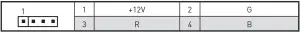
JRGB1: RGB LED connector (H410M PRO)
The JRGB connector allows you to connect the 5050 RGB LED strips 12V.
![]() Important
Important
- The JRGB connector supports up to 2 meters continuous 5050 RGB LED strips (12V/G/R/B) with the maximum power rating of 3A (12V).
- Always turn off the power supply and unplug the power cord from the power outlet before installing or removing the RGB LED strip.
- Please use MSI’s software to control the extended LED strip.
JRAINBOW1: Addressable RGB LED connector (H410M PRO)
The JRAINBOW connector allows you to connect the WS2812B Individually Addressable RGB LED strips 5V.
![]() CAUTIONDo not connect the wrong type of LED strips. The JRGB connector and the JRAINBOW connector provide different voltages, and connecting the 5V LED strip to the JRGB connector will result in damage to the LED strip.
CAUTIONDo not connect the wrong type of LED strips. The JRGB connector and the JRAINBOW connector provide different voltages, and connecting the 5V LED strip to the JRGB connector will result in damage to the LED strip.
![]() Important
Important
- The JRAINBOW connector supports up to 75 LEDs WS2812B Individually Addressable RGB LED strips (5V/Data/Ground) with the maximum power rating of 3A (5V). In the case of 20% brightness, the connector supports up to 200 LEDs.
- Always turn off the power supply and unplug the power cord from the power outlet before installing or removing the RGB LED strip.
- Please use MSI’s software to control the extended LED strip
UEFI BIOS
MSI UEFI BIOS is compatible with UEFI (Unified Extensible Firmware Interface) architecture. UEFI has many new functions and advantages that traditional BIOS cannot achieve, and it will completely replace BIOS in the future. The MSI UEFI BIOS uses UEFI as the default boot mode to take full advantage of the new chipset’s capabilities. However, it still has a CSM (Compatibility Support Module) mode to be compatible with older devices. That allows you to replace legacy devices with UEFI compatible devices during the transition.
![]() ImportantThe term BIOS in this user guide refers to UEFI BIOS unless otherwise noted.
ImportantThe term BIOS in this user guide refers to UEFI BIOS unless otherwise noted.
UEFI advantages
- Fast booting – UEFI can directly boot the operating system and save the BIOS self test process. And also eliminates the time to switch to CSM mode during POST.
- Supports for hard drive partitions larger than 2 TB.
- Supports more than 4 primary partitions with a GUID Partition Table (GPT).
- Supports unlimited number of partitions.
- Supports full capabilities of new devices – new devices may not provide backward compatibility.
- Supports secure startup – UEFI can check the validity of the operating system to ensure that no malware tampers with the startup process.
Incompatible UEFI cases
- 32-bit Windows operating system – this motherboard supports only 64-bit Windows 10 operating system.
- Older graphics card – the system will detect your graphics card. When display a warning message There is no GOP (Graphics Output protocol) support detected in this graphics card.
![]() ImportantWe recommend that you to use a GOP/ UEFI compatible graphics card.
ImportantWe recommend that you to use a GOP/ UEFI compatible graphics card.
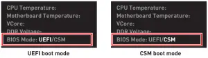
How to check the BIOS mode?
After entering the BIOS, find the BIOS Mode at the top of the screen.
BIOS Setup
The default settings offer the optimal performance for system stability in normal conditions. You should always keep the default settings to avoid possible system damage or failure booting unless you are familiar with BIOS.
![]() Important
Important
- BIOS items are continuous update for better system performance. Therefore, the description may be slightly different from the latest BIOS and should be held for reference only. You could also refer to the HELP information panel for BIOS item description.
- The BIOS items will vary with the processor.
Entering BIOS Setup
Press Delete key, when the Press DEL key to enter Setup Menu, F11 to enter Boot Menu message appears on the screen during the boot process.
Function key
F1: General HelpF2: Add/ Remove a favorite itemF3: Enter Favorites menuF4: Enter CPU Specifications menuF5: Enter Memory-Z menuF6: Load optimized defaultsF7: Switch between Advanced mode and EZ modeF8: Load Overclocking ProfileF9: Save Overclocking ProfileF10: Save Change and Reset*F12: Take a screenshot and save it to USB flash drive (FAT/ FAT32 format only). Ctrl+F: Enter Search page
* When you press F10, a confirmation window appears and it provides the modification information. Select between Yes or No to confirm your choice.
Resetting BIOS
You might need to restore the default BIOS setting to solve certain problems. There are several ways to reset BIOS:
- Go to BIOS and press F6 to load optimized defaults.
- Short the Clear CMOS jumper on the motherboard.
![]() ImportantPlease refer to the Clear CMOS jumper section for resetting BIOS.
ImportantPlease refer to the Clear CMOS jumper section for resetting BIOS.
Updating BIOS
Updating BIOS with M-FLASH
Before updating:
Please download the latest BIOS file that matches your motherboard model from MSI website. And then save the BIOS file into the USB flash drive.
Updating BIOS:
- Insert the USB flash drive that contains the update file into the USB port.
- Please refer the following methods to enter flash mode.▪ Reboot and press Ctrl + F5 key during POST and click on Yes to reboot the system.▪ Reboot and press Del key during POST to enter BIOS. Click the M-FLASH button and click on Yes to reboot the system.
- Select a BIOS file to perform the BIOS update process.
- When prompted click on Yes to start recovering BIOS.
- After the flashing process is 100% completed, the system will reboot automatically.
Updating the BIOS with Dragon Center
Before updating:
Make sure the LAN driver is already installed and the internet connection is set properly.
Updating BIOS:
- Install and launch MSI DRAGON CENTER and go to Support page.
- Select Live Update and click on Advance button.
- Click on Scan button to search the latest BIOS file.
- Select the BIOS file and click on Download icon to download and install the latest BIOS file.
- Click Next and choose In Windows mode. And then click Next and Start to start updating BIOS.
- After the flashing process is 100% completed, the system will restart automatically
Installing OS, Drivers & Utilities
Please download and update the latest utilities and drivers at www.msi.com
Installing Windows® 10
- Power on the computer.
- Insert the Windows®10 installation disc/USB into your computer.
- Press the Restart button on the computer case.
- Press F11 key during the computer POST (Power-On Self Test) to get into Boot Menu.
- Select the Windows® 10 installation disc/USB from the Boot Menu.
- Press any key when screen shows Press any key to boot from CD or DVD… message.
- Follow the instructions on the screen to install Windows® 10.
Installing Drivers
- Start up your computer in Windows® 10.
- Insert MSI® Driver Disc into your optical drive.
- Click the Select to choose what happens with this disc pop-up notification, then select Run DVDSetup.exe to open the installer. If you turn off the AutoPlay feature from the Windows Control Panel, you can still manually execute the DVDSetup.exe from the root path of the MSI Driver Disc.
- The installer will find and list all necessary drivers in the Drivers/Software tab.
- Click the Install button in the lower-right corner of the window.
- The drivers installation will then be in progress, after it has finished it will prompt you to restart.
- Click OK button to finish.
- Restart your computer.
Installing Utilities
Before you install utilities, you must complete drivers installation.
- Open the installer as described above.
- Click the Utilities tab.
- Select the utilities you want to install.
- Click the Install button in the lower-right corner of the window.
- The utilities installation will then be in progress, after it has finished it will prompt you to restart.
- Click OK button to finish.
- Restart your computer.
Regulatory Notices
FCC Compliance Statement
Note: This equipment has been tested and found to comply with the limits for a Class B digital device, pursuant to part 15 of the FCC Rules. These limits are designed to provide reasonable protection against harmful interference in a residential installation.This equipment generates, uses and can radiate radio frequency energy and, if not installed and used in accordance with the instructions, may cause harmful interference to radio communications. However, there is no guarantee that interference will not occur in a particular installation. If this equipment does cause harmful interference to radio or television reception, which can be determined by turning the equipment off and on, the user is encouraged to try to correct the interference by one or more of the following measures:
- Reorient or relocate the receiving antenna.Increase the separation between the equipment and receiver.
- Connect the equipment into an outlet on a circuit different from that to which the receiver is connected.
- Consult the dealer or an experienced radio/TV technician for help.
Caution: Changes or modifications not expressly approved by the party responsible for compliance could void the user’s authority to operate the equipment.

This device complies with part 15 of the FCC Rules. Operation is subject to the following two conditions:(1) This device may not cause harmful interference, and (2) this device must accept any interference received, including interference that may cause undesired operation
CE Conformity
 Products bearing the CE marking comply with one or more of the following EU Directives as may be applicable:RED 2014/53/EU; Low Voltage Directive 2014/35/ EU; EMC Directive 2014/30/EU; RoHS Directive 2011/65/EU.Compliance with these directives is assessed using applicable European Harmonized Standards. The point of contact for regulatory matters is MSI, MSI-NL Eindhoven 5706 5692 ER Son.
C-Tick Compliance

Battery Information
European Union:![]() Batteries, battery packs, and accumulators should not be disposed of as unsorted household waste. Please use the public collection system to return, recycle, or treat them in compliance with the local regulations.
Batteries, battery packs, and accumulators should not be disposed of as unsorted household waste. Please use the public collection system to return, recycle, or treat them in compliance with the local regulations.
Taiwan:![]() For better environmental protection, waste batteries should be collected separately for recycling or special disposal.
For better environmental protection, waste batteries should be collected separately for recycling or special disposal.
California, USA:![]() The button cell battery may contain perchlorate material and requires special handling when recycled or disposed of in California.For further information please visit: http://www.dtsc.ca.gov/hazardouswaste/perchlorateCAUTION: There is a risk of explosion, if battery is incorrectly replaced.Replace only with the same or equivalent type recommended by the manufacturer.
The button cell battery may contain perchlorate material and requires special handling when recycled or disposed of in California.For further information please visit: http://www.dtsc.ca.gov/hazardouswaste/perchlorateCAUTION: There is a risk of explosion, if battery is incorrectly replaced.Replace only with the same or equivalent type recommended by the manufacturer.
WEEE (Waste Electrical and Electronic Equipment) Statement To protect the global environment and as an environmentalist, MSI must remind you that… Under the European Union (“EU”) Directive on Waste Electrical and Electronic Equipment, Directive 2002/96/EC, which takes effect on August 13, 2005, products of “electrical and electronic equipment” cannot be discarded as municipal wastes anymore, and manufacturers of covered electronic equipment will be obligated to take back such products at the end of their useful life. MSI will comply with the product take back requirements at the end of life of MSI-branded products that are sold into the EU. You can return these products to local collection points.
India RoHS
This product complies with the “India E-waste (Management and Handling) Rule 2011” and prohibits use of lead, mercury, hexavalent chromium, polybrominated biphenyls or polybrominated diphenyl ethers in concentrations exceeding 0.1 weight % and 0.01 weight % for cadmium, except for the exemptions set in Schedule 2 of the Rule.
Environmental Policy
- The product has been designed to enable proper reuse of parts and recycling and should not be thrown away at its end of life.
- Users should contact the local authorized point of collection for recycling and disposing of their end-of-life products.
- Visit the MSI website and locate a nearby distributor for further recycling information.Users may also reach us at [email protected] for information regarding proper Disposal, Take-back, Recycling, and Disassembly of MSI products.
Chemical Substances InformationIn compliance with chemical substances regulations, such as the EU REACH Regulation (Regulation EC No. 1907/2006 of the European Parliament and the Council), MSI provides the information of chemical substances in products at:https://storage-asset.msi.com/html/popup/csr/evmtprtt_pcm.html
Copyright
![]() Micro-Star Int’l Co.,Ltd.Copyright © 2020 All rights reserved.The MSI logo used is a registered trademark of Micro-Star Int’l Co., Ltd. All other marks and names mentioned may be trademarks of their respective owners. No warranty as to accuracy or completeness is expressed or implied. MSI reserves the right to make changes to this document without prior notice.
Micro-Star Int’l Co.,Ltd.Copyright © 2020 All rights reserved.The MSI logo used is a registered trademark of Micro-Star Int’l Co., Ltd. All other marks and names mentioned may be trademarks of their respective owners. No warranty as to accuracy or completeness is expressed or implied. MSI reserves the right to make changes to this document without prior notice.
Revision History
Version 1.0, 2020/06, First release.Version 1.2, 2020/07, add H410M PRO-VH.Version 1.3, 2020/10, updated release.
Technical Support
If a problem arises with your system and no solution can be obtained from the user guide, please contact your place of purchase or local distributor. Alternatively, please try the following help resources for further guidance.
- Visit the MSI website for technical guide, BIOS updates, driver updates, and other information: http://www.msi.com
- Register your product at: http://register.msi.com
 report this ad
References
[xyz-ips snippet=”download-snippet”]