![]()
OWNER’S MANUALMUD100.4 AMPLIFIER http://mitk.co/BYJUse your smartphone to scan and learn more about all of the all-weather solutions available from MTX Audio.
PRODUCT INFORMATION
Model # ____________Serial # ______________Dealer’s Name _________Date of Purchase________
INTRODUCTION
Thank you for purchasing this MTX Audio Hi-Performance amplifier. Proper installation matched with MTX speakers and subwoofers provides superior sound and performance for endless hours of enjoyment whether you are waking the neighbors or just out enjoying your tunes. Congratulations and enjoy the ultimate audio experience with MTX!
FEATURES
- Compact Size
- Double-Sided PCB
- Surface Mount Components
- MOSFET Design
- LPF and HPF Crossover
- Noise Free Design
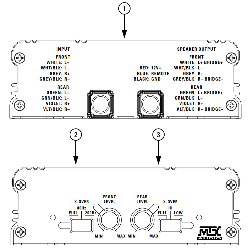
CONTROL FUNCTIONS
- Wiring Harness – All wiring to the amplifier will run through the wiring harness.Speakers – Connect speakers/subwoofers to these terminals. Be sure to check the wire for proper polarity. Never connect the speaker cables to the chassis ground.+BATT (+12 Volt Power) – Connect this terminal through a FUSE or CIRCUIT BREAKER to the positive terminal of the vehicle battery or the positive terminal of an isolated audio system battery.WARNING: Always protect this power cable by installing a fuse or circuit breaker of the appropriate gauge within 18 inches (45cm) of the battery terminal connection. Remote Turn On – This terminal turns on the amplifier when (+) 12 volt is applied to it. Connect it to the remote turn-on lead of the head unit or signal source.GND – connect this cable directly to the frame of the vehicle. Make sure the metal frame has been stripped of all paint down to the bare metal. Use the shortest distance possible. If a suitable ground point is not available on the frame, connect this terminal directly to the vehicle battery ground terminal, or any other factory ground points. RCA Input Jacks – This unit is designed to function with source units that feature RCA outputs. If your source unit does not have RCA outputs you will need to use the speaker level inputs. A source unit with a minimum level of 200mV is required for proper operation.
- Gain Control – The Gain control will match the amplifier’s sensitivity to the source unit’s signal voltage. The operating range is 10V to 200mV. NOTE: This is NOT a volume control.
- X-Over Mode – These controls allow control over the frequencies played. There is an option for Full, 80Hz, or 200Hz on the front channels, and an option for Full Range, High Pass, or Low Pass on the rear channels.
PANEL LAYOUT
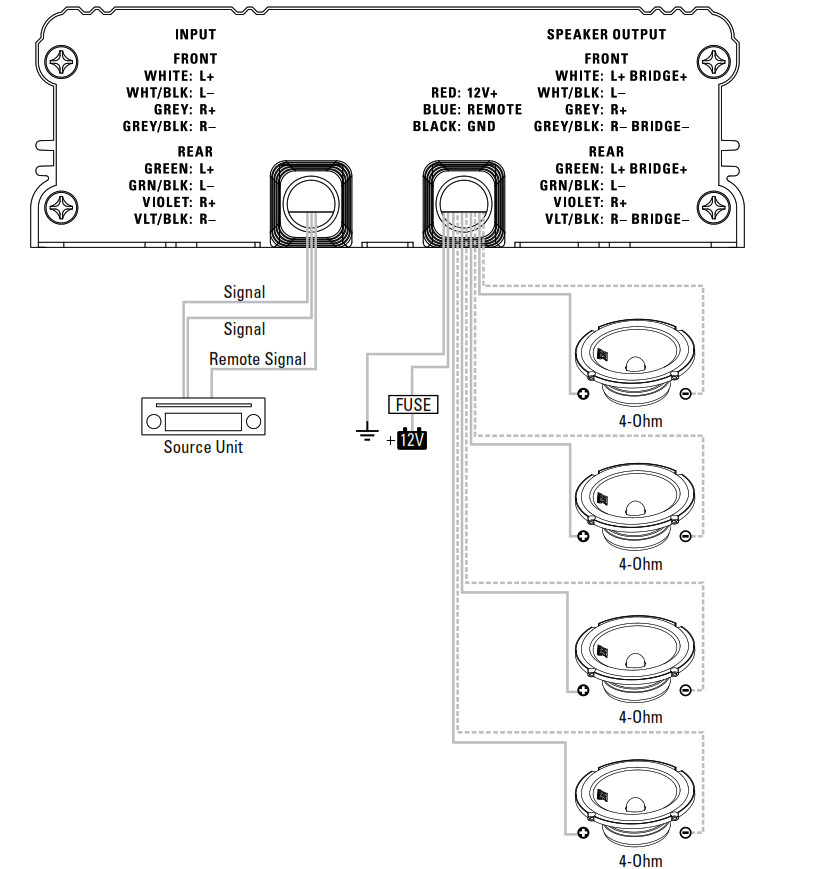
WIRING DIAGRAM
See page 22 for amplifier wiring diagrams.
INSTALLATION AND MOUNTING
MTX recommends your new Thunder Sports ™ amplifier be installed by a 12-volt installation specialist. Any deviation from specified installation instructions can cause serious damage to the amplifier, speakers, and/or vehicle’s electrical system. Damage caused by an improper installation is NOT covered under warranty. Please verify all connections prior to the system turn on.
- Disconnect the vehicle’s negative battery cable.
- Determine the mounting place for your MTX amplifier. Keep in mind there should be sufficient airflow for proper cooling. Mark the mounting holes from the amplifier to be drilled. Before drilling makes sure all vehicle wires, gas lines, brake lines, and gas tanks are clear and will not interfere with installation. Drill the desired holes and mount the MTX amplifier.
- Install a positive (+) power cable from the vehicle’s battery through the firewall using a grommet or firewall bushing to avoid cable damage from sharp edges of the firewall. Run the cable through the interior of the vehicle and connect it to the amplifier’s +12V wire. Do not connect to the battery at this time. NOTE: Use only proper gauge wire for both positive and negative connections.
- Install a circuit breaker or fuse within 18 inches of the battery. This effectively lowers the risk of severe damage to you or your vehicle in case of a short circuit or accident. Make sure the circuit breaker is switched Off or the fuse is taken out of the fuse holder until all connections are made. Now connect your positive power cable to the positive battery terminal of the battery.
- Grounding – Locate a proper ground point on the vehicle’s chassis and remove all paint, dirt, or debris to reveal a bare metal surface. Attach the amplifier’s ground wire to that contact point. If a suitable location is not available connect this terminal to the vehicle’s negative battery terminal.
- Connect a Remote Turn-On wire from the source unit to the MTX amplifier’s (REM) wire. If the source unit does not have a dedicated Remote Turn-On lead, you may connect to the source unit’s Power Antenna lead.
- Supply the signal to your MTX amplifier by connecting the signal cables using high-quality RCA or speaker wires to the corresponding outputs at the source unit and inputs of the amplifier.
- Connect your speakers to your MTX amplifier’s speaker wires using the correct gauge speaker wire. Your MTX amp can drive a 2 Ω stereo/4Ω bridged minimum load for optimum power.
- Double-check all previous installation steps, in particular, wiring and component connections. Once verified, reconnect the vehicle’s negative battery cable, turn the circuit breaker on or place the fuse in the fuse holder.NOTE: Gain Levels on the amplifier should be turned all the way down (counterclockwise) before proceeding with adjustments.
INSTALLATION
For proper performance and safety, MTX recommends installing an inline fuse per the owner’s manual instructions according to the following.
| MUD100.4 | 30A Fuse |
TROUBLESHOOTING
| Problem | Cause |
Solution |
|
Output Distorted |
Head Unit Volume Set Too High |
Lower Head Unit Volume |
|
Amplifier Gain Set Too High |
Lower Amplifier Gain |
|
|
Balance Reversed |
Speaker Wire L & R Reversed |
Correct Speaker Wire Orientation |
|
RCA Inputs Reversed |
Reverse RCA Inputs |
|
|
Bass is Weak |
Speakers Wired Out of Phase |
Wire Speakers with Correct Phase |
|
Not Using MTX Subwoofers |
Buy MTX Subwoofers |
|
|
Blowing Fuses |
Excessive Output Levels |
Lower the Volume |
|
Amplifier Defective |
Return for Service |
SPECIFICATIONS
| Model |
MUD100.4 |
| Description | 50 W RMS/CH Stereo |
| RMS Power at 14.4V | |
|
4.2 Bridged Load |
200 W RMS |
|
2Q. Load |
100 W RMS |
| 4.Q. Load |
50 W RMS |
|
Features |
|
|
Input Level |
0.2 – 5V Low Level, 0.4 – 10V High Level |
|
Frequency Response |
10Hz – 32 kHz |
|
Low Pass Filter (LPF) Rear Only |
80Hz Fixed |
|
High Pass Filter (HPF) Rear |
80Hz Fixed |
| High Pass Filter (HPF) Front Selectable |
80/200Hz |
|
THD at 4.2 , 1W |
<0.2% |
| Signal-to-Noise Ratio |
>75dB |
|
Minimum Load |
2Ω |
| Low Voltage Protection |
Yes, Protect <8.5V |
|
Components & PCB |
SMD Parts / Double Sided FR-4 PCB |
|
Dimensions |
|
|
Height |
1.86″ (47.2mm) |
| Width |
5.51″ (140mm) |
|
Length |
6.52″ (165.5mm) |
WIRING DIAGRAM
4Ω Stereo
WIRING DIAGRAM2Ω Stereo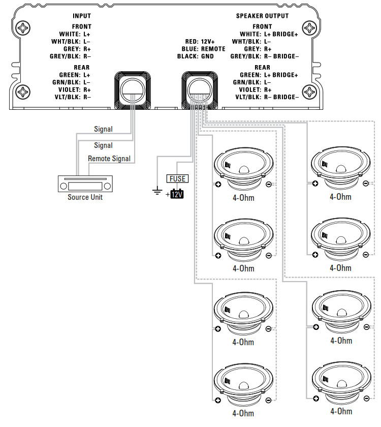 WIRING DIAGRAMStereo 4 Ω Front/4Ω Bridged Rear
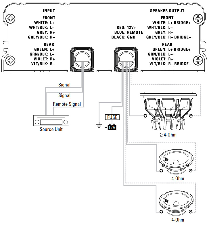
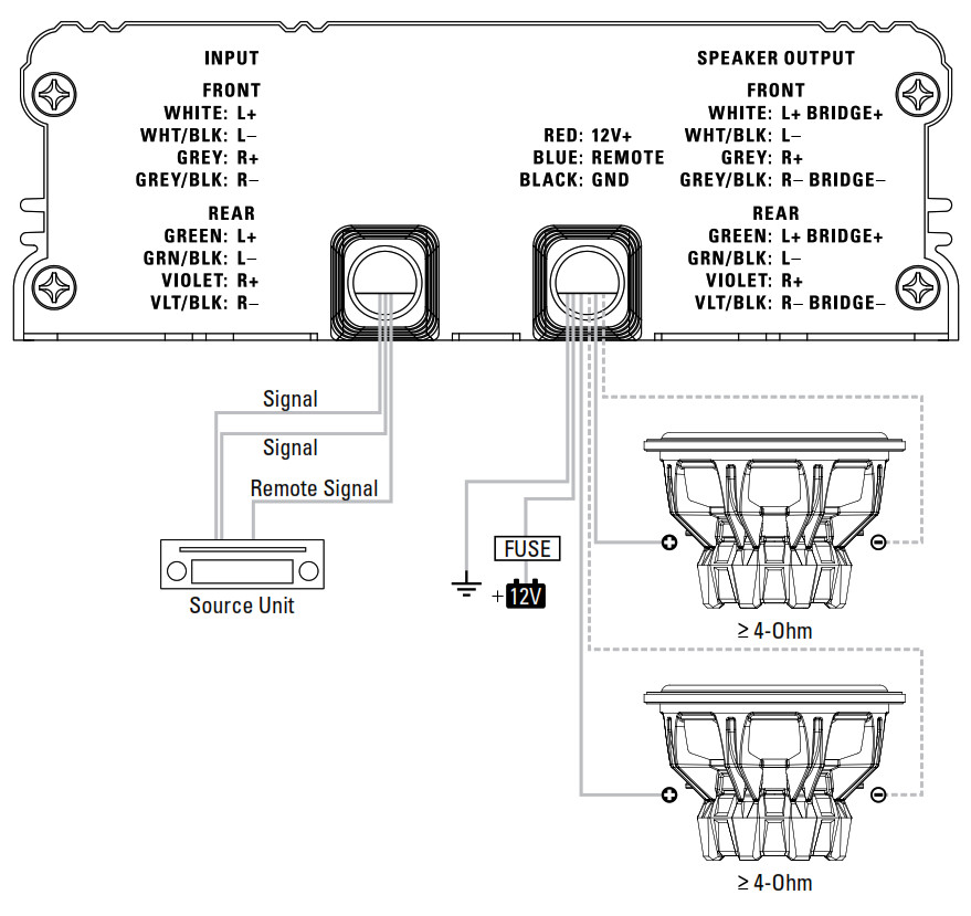
WIRING DIAGRAM4Ω Bridged Subwoofers
![]()
© 2015 Mitek Corporation. All rights reserved. MTX is a trademark of Mitek Corporation. Designed and Engineered in the U.S.A.Due to continual product development, all specifications are subject to change without notice.MTX Audio, 4545 East Baseline Rd. Phoenix, AZ 85042 U.S.A.MTX005172 RevA 4/15 • 21A10394 • AW0015062
[xyz-ips snippet=”download-snippet”]