Statement
Any content of this manual may not be reproduced in any form ( including stored, retrieved or translated into other languages without the permission and written consent in accordance with international copyright laws. This manual is subject to change in future versions without further notice .
(Caution)
The “Caution” sign indicates conditions and actions that could cause damage to the meter or equipment.
It requires that the operation must be careful. Miss operation or improper procedure may cause damage to the meter or equipment. Do not proceed with any of the actions indicated by the caution signs If these conditions are not met or are not fully understood.
Warning
The “Warning” sign indicates conditions and actions that are dangerous to the user.
It requires that the operation must be paid attention. Miss operation or improper procedure may cause damage to the meter or equipment. Do not proceed with any of the actions indicated by the caution signs If these conditions are not met or are not fully understood.
Please read the instructions carefully and pay attention to the safety warnings before using the meter.
Introduction
This watch is a digital multimeter that can be carried around. It has stable performance, high precision, low power consumption, novel structure, safety and reliability, and is an ideal measuring meter for users.The meter can measure DC voltage, AC voltage , DC current, AC current, resistance, diode, continuity and capacitance with non-contact voltage detection function to remind users operating safety, making the operation safer for users.This manual contains relevant safety information and warnings, etc. Please read the contents carefully before using the meter and strictly abide by all warnings and precautions.
Safety instructions
This digital Multimeter is designed and manufactured in accordance with the the safety requirements of IEC-61010. It meets the requirements of double insulation, 600V CAT Ill and pollution level 2 of IEC61010. Before using the Multimeter, please read the users manual carefully, otherwise the protection function may be reduced or invalid.
Safety standard operation warning
To avoid possible electric shock or personal jury, please strictly abide by the following specifications:
- Please read “Safety Information” before using the meter. And use the meter in accordance with the regulations, otherwise the protection function may be reduced or Statement
- Any content of this manual may not be reproduced in any form ( including stored, retrieved or translated into other languages without the permission and written consent in accordance with international copyright laws. This manual is subject to change in future versions without further notice .
(Caution)
The “Caution” sign indicates conditions and actions that could cause damage to the meter or equipment.
It requires that the operation must be careful. Misoperation or improper procedure may cause damage to the meter or equipment. Do not proceed with any of the actions indicated by the caution signs If these conditions are not met or are not fully understood .
(Warning)
The “Warning” sign indicates conditions and actions that are dangerous to the user. It requires that the operation must be paid attention. Misoperation or improper procedure may cause damage to the meter or equipment. Do not proceed with any of the actions indicated by the caution signs If these conditions are not met or are not fully understood.Please read the instructions carefully and pay attention to the safety warnings before using the meter.
To avoid possible electric shock or personal jury, please strictly abide by the following specifications:
- Please read “Safety Information” before using the meter. And use the meter in accordance with the regulations, otherwise the protection function may be reduced or invalid.
- Check the case before using the meter. Check for cracks or missing plastic parts. Please carefully check the insulation near the input tenninals
- Do not use the meter if it is not working properly or is dama ged.
- It is forbidden to touch the charged body with voltage exceeding 30V true RMS AC, 42V AC peak or 60V DC.
- The meter should be used according to the specified measurement category, voltage or current rating.
- Replace the the battery as soon as the insufficient battery indicator appears. Insufficient battery power may cause incorrect meter readings
- Please comply with local and national safety regulations, wear personal protective equipment (qualified rubber gloves, masks, and flame retardant clothing , etc.) to protect yourself from electric shock and arcing when live conductors are exposed
- The voltage applied between the input terminals or between each terminal and the grounding point shall not exceed the rated value specified by the Meter.
- Measure a setpoint voltage to determine if the meter is operating properly.
- Use the correct input terminal, function position and range position when measuring.
- Do not use the Meter around explosive gas, vapor or humid environment
- Do not use a damaged probe. Check if there are damage, exposed metal or signs of wear of the insulation layer of the probe. Check the continuity of the probe.
- When measuring, connect the neutral or ground wire first, then connect the live wire; when disconnecting, please cut off the live wire first, then disconnect the neutral wire and ground wire.
- When using probes, keep your fingers behind the finger guards on the probes.
- Disconnect the probe and the objects to be measured before opening the back cover of the Meter.
- Do not use the meter in an environment that exceeds the measurement category (CAT) rating of the individual component with the lowest rating in the meter, probe, or accessories.
Electrical Symbols
- Warning of high voltage AC (Alternating current) DC (Direct current)
- AC or DC
- ARNING, important safety signs Earth ground
- Fuse
- Equipment is protected by double insulted or reinforced insulation Insufficient power of the battery
- Conforms to European Union directive
- Do not discard such electrical/electronic products in household waste. Category II measurements are suitable for testing and measuring circuits that are directly connected to the power points (sockets and similar points) of a low voltage power supply unit.
- Category II measurements are suitable for testing and measuring circuits connected to the power distribution section of a building’s low voltage power supply unit
- Category IV measurements are suitable for testing and measuring circuits connected to the low voltage power supply unit ofa building.
Meter Indication
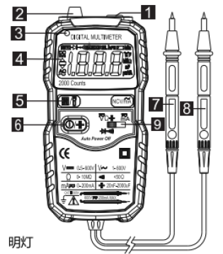
- illuminator
- non-contact voltage induction zone
- non-contact voltage indicator
- display
- pushbutton
- red probe
- black probe
- function switch
Switch of backlight and illumination and data hold button Click to open the data hold, then click to cancel the data hold Press and hold for more than 2 seconds , turn on the backlight and illumination turn off Clean the case with a damp cloth and a small amount of detergent. Do not use abrasives or chemical solvents. Input terminal that are dirty or damp may affect readings.
Replacing the battery and the fuse
In order to avoid electric shock or personal injury caused by incorrect reading, the battery should be replaced as soon as possible when the low voltage symbol ![]() ” display appears.
” display appears.
To ensure safety operation and maintain the equipment, please remove the battery to avoid the damage to the equipment of the leaked battery when not in use for a long time. In order to avoid electric shock or personal injury, shut down and check that the probe has been disconnected from the measuring circuit before open the battery cover and replace the battery. Replace the battery as follows:
- Turn off the power of the Meter.
- Disconnected the probes from the the measuring circuit.
- Loosen the screws that secure the battery cover with a wire cutter and remove the battery cover
- Take away the old battery and replace with a new one. 7 Attach the battery cover and tighten the screws.
Clean the case with a damp cloth and a small amount of detergent. Do not use abrasives or chemical solvents. Input terminal that are dirty or damp may affect readings.
invalid
- Check the case before using the meter . Check for cracks or missing plastic parts. Please carefully check the insulation near the input terminals
- Do not use the meter if it is not working properly or is dama ged.
- It is forbidden to touch the charged body with voltage exceeding 30V true RMS AC, 42V AC peak or 60V DC.
- The meter should be used according to the specified measurement category, voltage or current rating.
- Replace the the battery as soon as the insufficient battery indicator appears. Insufficient battery power may cause incorrect meter readings
- Please comply with local and national safety regu l ati ons , wear personal protective equipment (qualified rubber gloves, masks , and flame retardant clothing , etc.) to protect yourself from electric shock and arcing when live conductors are exposed
- The voltage applied between the input terminals or between each terminal and the grounding point shall not exceed the rated value specified by the Meter.
- Measure a setpoint voltage to determine if the meter is operating properly.
- Use the correct input terminal, function position and range position when measuring.
- Do not use the Meter around explosive gas, vapor or humid environment
- Do not use a damaged probe. Check if there are damage, exposed metal or signs of wear of the insulation layer of the probe. Check the continuity of the probe.
- When measuring, connect the neutral or ground wire first, then connect the live wire; when disconnecting, please cut off the live wire first, then disconnect the neutral wire and ground wire.
- When using probes, keep your fingers behind the finger guards on the probes.
- Disconnect the probe and the objects to be measured before opening the back cover of the Meter.
- Do not use the meter in an environment that exceeds the measurement category
(CAT) rating of the individual component with the lowest rating in the meter ,probe, or accessories.
Diode
Automatically after about 15 seconds or press again and keep it manually for more than 2 seconds
|
200Q |
0.1 Q |
±(1.0% + 3) |
|
2KQ |
0.00!kQ |
|
|
20KQ |
10.0lkQ |
|
|
200KQ |
0.lkQ |
|
|
2MQ |
0.00IMQ |
|
|
20MQ |
0.0IMQ |
±(1.2%+15) |
Non-contact voltage detection, AC current and DC current measurement selection keys
Power switch and capacitance measurement selection button, long press to turn on or press and keep more than 2 seconds to shut down. short press to switch to capacitance measurement funct ion, the meter will automatically cut off if there is no operation after about 15 minutes , and the buzzer will alert I minute before shutdown.
Function, Range, Resolution
Testing conditions
Measuring guide, AC and DC voltage/resistance /diode/continuity testing, AC DC voltage I resistance / diode measurement connectivity test Press the power button to turn on the meter and put the function selector switch at the position of Overload protection:600V DC/AC RMS
|
Diode testing
|
IV |
0.00IV |
Forward DC current: about lmA; open-circuit voltage: about 2.8V Display shows the approximate value of diode forward voltage drop |
4.2.6 Continuity buzzer
Connect the test leads in parallel to the circu it, power supply, resistor or diode to be tested. The meter automatically detentions the DC voltage, AC voltage, resistance,
Overload protection:600V DC/AC RMS
4.2.8 Capacitance
Overload protection:600V DC/AC RMS
Testing conditions and diode.
- When the resistance of the circuit under test is not more than about 50Q , the buzzer emits a continuous sound.
- Read the measurement results from the display. When measuring DC voltage, the display also shows the voltage polarity of the test point of red probe.
- Press the power switch key and hold it for 2 seconds to turn off the meter power when the measurement is done.
Warning
- Do not input a voltage higher than 600V. It is possible to display a higher voltage value, but there may be damage to the meter .
- When measuring high voltage, be extremely careful of electric shock.
- After completing all measurement and measurement operations, disconnect the probe from the circuit under test.
Capacitance measurement
|
|
The resistance of the circuit under test is not more than about 50, when the buzzer emits a continuous sound. |
Forward DC current: about I mA; open-circuit voltage: about 2.8V |
|
Range |
Resolution |
Accuracy |
|
20nF |
0.01 nF |
±(10% + 40) |
|
600nF |
0.lnF |
±(2.5% + 20) |
|
2uF |
lnF |
|
|
20uF |
!0nF |
|
|
200uF |
l00nF |
|
|
2000uF |
luF |
±(5% + 10) |
- Press the power button to turn on the meter and put the function selector switch at the position of
Meter maintenance
This section provides basic maintenance information, including instructions for replacing the fuse and replacing the battery. To avoid electric shock or personal injury, repairs should be performed by qualified personnel with relevant information of calibration, performance test and maintenance .
Warning: In order to avoid possible electric shock, fire or personnel injury , do not perform any measurement with the Meter when the outer casing is opened. Remove the input signal before clean the meter.
General maintenance
|
200Q |
0.1 Q |
±(1.0% + 3 ) |
|
2KQ |
0.00lkQ |
|
|
20KQ |
10.0lkQ |
|
|
200KQ |
0.lkQ |
|
|
2MQ |
0.00IMQ |
|
|
20MQ |
0.0IMQ |
±(1.2% + 15) |
Overload protection:600V DC/AC RMS
- Short press the key to switch to the capacitance measurement function.
- Connect the two ends of the probes of the capacitors and read the measurement results from the display.
Note: When measuring high capacitance, it takes time to stabilize the readings. Warning:
- To avoid damage to the Meter or to the equipment under test, disconnected circuit power and discharged all high-voltage capacitors before measuring capacitance. To determine that the capacitor has been discharged adopting by the DC voltage file. automatically after about 15 seconds or press again and keep it manually for more than 2 seconds

Non-contact voltage detection , AC current and DC current measurement selection keys
Power switch and capacitance measurement selection button, long press to turn on or press and keep more than 2 seconds to shut down. short press to switch to capacitance measurement function, the meter will automatically cut off if there is no operation after about 15 min utes , and the buzzer will alert I minute before shutdown.
|
Diode testing
|
IV |
0.00IV |
Forward DC current: about lmA; open-circuit voltage: about 2.8V Display shows the approximate value of diode forward voltage drop |
Press the power button to turn on the meter and put the function selector switch at the position of
Overload protection:600V DC/AC RMS
Continuity buzzer
Connect the test leads in parallel to the circuit, power supply, resistor or diode to be tested. The meter automatically determines the DC voltage, AC voltage, resistance,
Capacitance
Overload protection:600V DC/AC RMS
Testing conditions and diode.
- When the resistance of the circuit under test is not more than about 50Q , the buzzer emits a continuous sound.
- Read the measurement results from the display. When measuring DC voltage, the display also shows the voltage polarity of the test point of red probe.
- Press the power switch key and hold it for 2 seconds to turn off the meter power when the measurement is done.
Warning
- Do not input a voltage higher than 600V. It is possible to display a higher voltage value, but there may be damage to the meter.
- When measuring high voltage, be extremely careful of electric shock.
- After completing all measurement and measurement operations, disconnect the probe from the circuit under test.
Capacitance measurement
|
|
The resistance of the circuit under test is not more than about 50, when the buzzer emits a continuous sound. |
Forward DC current: about l mA; open-circuit voltage: about 2.8V |
|
Range |
Resolution |
Accuracy |
|
20nF |
0.01 nF |
±(10% + 40) |
|
600nF |
0.lnF |
±(2.5% + 20 ) |
|
2uF |
lnF |
|
|
20uF |
I0nF |
|
|
200uF |
I00nF |
|
|
2000uF |
luF |
±(5% + 10) |
- Press the power button to turn on the meter and put the function selector switch at the position of
Meter maintenance
This section provides basic maintenance information, including instructions for replacing the fuse and replacing the battery. To avoid electric shock or personal injury, repairs should be performed by qualified personnel with relevant information of calibration, performance test and maintenance.
Warning: In order to avoid possible electric shock, fire or personnel injury, do not perform any measurement with the Meter when the outer casing is opened. Remove the input signal before clean the meter.
General maintenance
- Short press the key to switch to the capacitance measurement function.
- Connect the two ends of the probes of the capacitors and read the measurement results from the display.
Note: When measuring high capacitance, it takes time to stabilize the readings . Warning:
- To avoid damage to the Meter or to the equipment under test, disconnected circuit power and discharged all high-voltage capacitors before measuring capacitance. To determine that the capacitor has been discharged adopting by the DC voltage file.
Precision index
Accuracy is suitable after one year from the date of calibration.
Reference conditions: 18 ° C to 28 ° of the ambient tempera ture, relative humidity not more than 80%
DC voltage
|
Range |
Resolution |
Accuracy |
|
2V |
0.001V |
±(0.5% + 3) |
|
20V |
0.0IV |
|
|
200V |
0. IV |
|
|
600V |
IV |
±(0.8% + 3) |
Input impedance: I0MQ
Maximum input voltage: 600Vdc or ac RMS
AC voltage
|
Range |
Resolution |
Accuracy |
|
2V |
0.001V |
±(0.8% + 3) |
|
20V |
0.0IV |
|
|
200V |
0. I V |
|
|
600V |
IV |
±(1.0% + 3) |
Input impedance: J0MQ
Maximum input voltage: 600Vdc or ac RMS Frequency response: 40Hz-400Hz ;
DC current
- 600 V CATMV and l000VCAT.Ill
- The altitude is <2000m.
- Pollution level: 2
- Input protection: self-recovery fuse of 200mA/265V
- Temperature and humidity of the working environment: 0 – 40C (<80% RH, when the temperature <10 ° C, it is not considered)
- Temperature and humidity of storage environment: -IO – 60CC (<70% RH, remove the battery)
- Maximum voltage can be allowed between the measuring terminal and the earth ground: 600 V DC or AC RMS
- Protection of self-recovery fuse 200mA/265V
- Sampling rate: about 3 times / sec
AC current
|
Range |
Resolution |
Accuracy |
|
20mA |
0.0lmA |
±(2.0%+ 3) |
|
200mA |
0.lmA |
Input protection: self-recovery fuse of200mA/265V
Digital Multimeter User Manual S830 – Digital Multimeter User Manual S830 –
[xyz-ips snippet=”download-snippet”]