
User Manual
Professional Digital Multimeter FY76
1. Security Information
![]() Warning
Warning
People who use this meter should pay special attention to it, because the improper use might cause electric shock or damage to the meter. Please follow the actual safety rules and safety measures as specified in the manual.
To fully use the function of this meter and ensure its safety operation, please read and follow its usage methods in the specification carefully.
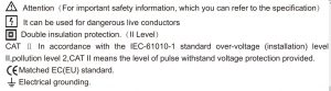
This meter matched the technical requirement of digital multimeter GB/T 13978-92 and the safety requirement of electronic measuring meter GB4793.1-1995 (IEC-61010-1. It belongs to secondary pollution and its over-voltage standard is CAT I 600V. Please follow the safe operation guide and ensure safe use for this meter. Proper use and maintenance for meter will give you a satisfied service.
1.1 Preparation
- Users must follow the standard safety rules when using it: – Need some universal protection to avoid electric shock. – To avoid misuse the meter.
- Check if there is any damage on this meter or not in the process of transportation when received it.
- Check if there is any damage on this meter or not when preserved, loaded and delivered it in poor condition.
- The test lead must be in a good condition.Check whether there is any damage on its insulation or not and if meter’s metal wire is exposed or not before using it.
- Using the test lead provided by meter can guarantee the use of meter safety.If needed, you must use the same or similar pen to replace it.
1.2 Usage
- The correct function and measuring range must be guaranteed when using it.
- Don’t overtake the indicating value of protection extent of every measuring range when testing.
- Don’t touch the top of test lead (the metal part) when linked meter with measuring circuit.
- When testing, if the voltage tested is over 60V DC or 30V AC (RMS),please keep your fingers behind the test lead protector.
- When the measuring terminal voltage is over 600V DC or 600V AC, please stop testing voltage.
- Before turning the switch to change the testing function, the test lead should be removed from the measuring circuit.
- Do not measure resistance, capacitance, diodes and lines when the line is energized
- When use current resistance,capacitor, diode and circuit breaker,user should avoid to link meter with voltage source.
- Don’t test capacitance before the capacitor is fully discharged.
- Don’t use the meter under the explosive gas, steam or dust environment.
- If there is any abnormality or malfunction in the meter, user should stop using it.
- Multimeter should not be used unless the meter bottom shell and the battery cover are completely clasped in place.
- Don’t preserve or use meter in the condition of direct sunlight, high temperature, high humidity.
1.3 Mark
1.4 Maintenance
- Please do not attempt to open the meter bottom shell to adjust or repair the meter, such operation only can be performed by technician who fully understands the instrument and the electric shock hazard.
- Before opening the meter bottom shell or battery cover,meter pen should be removed from the testing wire.
- In order to avoid the wrong readout which might cause possible electric shock when the meter displays the user should change battery right now.
- Use a damp cloth and a mild detergent to clean meter, but don’t use abrasives or solvents to clean it.
- When meter is not in use, the meter power shall be turned off and the meter range switch should be turned to “OFF”.
- If meter is idle for a long time, meter battery should be removed in case of causing damage meter.
2. Description
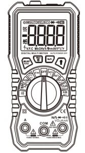
- This multimeter is a portable, professional measuring meter with a LCD display, and a backlight, which is easy to read for users.the range switch and one-hand operation is easy for use to test , it also has the overload protection function and low battery indication function. It is an ideal multi-functional meter for professionals, factories, schools, meter-lovers and families.
- This multimeter is applicable for AC-current, DC-current, AC-voltage, DC-voltage, frequency,duty cycle,resistance,capacitance measurement, wire test, and diode test.
- This meter has a function of reading retention.
- This meter has non-contact detection (NCV) .AC voltage function.
- The meter AC-current and AC-voltage test readout is true and valid.
- This meter has automatic shutdown function.
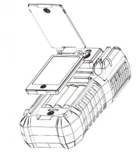
2.1 Component Name
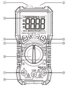
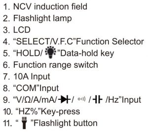
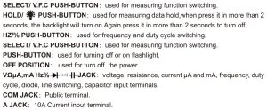
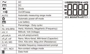
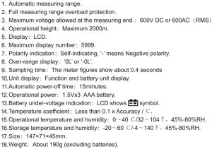
2.3 LCD Display
3. Specifications
3.1 Review
3.2 Technical index
3.2.1 TRMS and zero Input characteristics
- As for the measurement of non-sinusoidal signals, the TRMS method has less error than the traditional average value response method.
- True RMS meter can accurately measure the non-sinusoidal wave signal, but if it’s on the AC function mode or in the condition of no input signal measured(For example, in the input terminal short circuit or in the ac voltage mode), clamp table may show a readout of between 1 to 50. These deviation readings are normal. They do not influence the accuracy of the multimeter which is used for testing alternating current in the specified measuring range.
- True RMS requires meter input signal to reach a certain level for being measured. Therefore, the measuring range of AC voltage and current is specified between 2 % – 100 % of the full measuring range.
- In order to guarantee the accuracy of AC measurement,the input signal must be the following: – AC voltage: more than 13mV
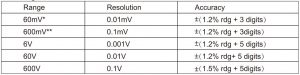
3.2.2 DC voltage
Accuracy: + (a% rdg +digits), Warranty for one year (Operating temperature: 23 + 5C Relative humidity: <75%)
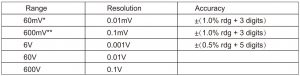
– Input impedance: *Measuring range2100M2. **Measuring range21G22. All other input impedance of measuring range is 10M2. (*/**The measuring range opening circuit might show unstable figures on the LCD screen, but it will be stable after connecting loadings1 word) Maximum input voltage: 600V DC
3.2.3 AC voltage AC voltage measurement
– Input impedance: All other input impedance of measuring range is 10M2. (*/**The measuring range opening circuit might show unstable figures on the LCD screen, but it will be stable after connecting loadings1 word) Display true RMS, frequency response: 45~1KHz
(V.F.C 45~400Hz) Guaranteeing the range of accuracy: 5%~100%measuring range, Short circuit is allowed<It can reach 3.0 when the remaining reading of 10 base words and AC crest factor is at full value >(Apart from 600V measuring range,it is 1.5 when measuring range changed is at full value) Maximum input voltage: 600V AC (RMS)
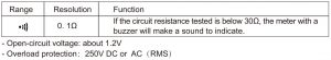
3.2.4 Resistance
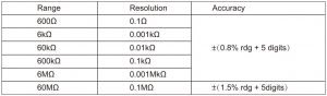
- Open-circuit voltage: about 0.4V
- Overload protection: 250V DC or AC (RMS)
3.2.5 Capacitance
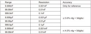
-Overload protection: 250V DC or AC (RMS)
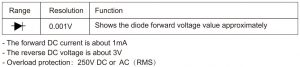
3.2.6 Diode Test
3.2.7 Circuit on – off Test
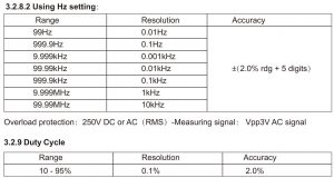
3.2.8 Frequency
3.2.8.1 Using V Setting or current setting:
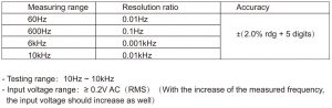
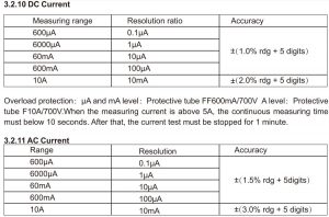
Overload protection: uA and mA level: Protective tube FF600mA/700V A level: Protective tube F10A/700V. Frequency range: 50 – 60Hz When the measuring current is above 5A, the continuous measuring time must below 10 seconds. After that, the current test must be stopped for 1 minute.
4. Operation guidance
4.1 Reading-holding
- In the process of measurement, if need reading-holding, users can press “HOLD” key,which LCD screen will show the display value that has been locked.
- Press the HOLD”key again, users can remove the reading-holding mode.
4.2 Flashlight
4.3 Function switch
- In the condition of AC mode,if press “SELECT/V.F.C” key for over 2 seconds,meter screen will switch to V.F.C mode. Meanwhile,the meter screen will display V.F.C prompt which can measure the variable frequency voltage reliably.If again press “SELECT/V.F.C” for over 2 seconds, the meter screen will show “Exit V.F.C measurement mode” and the prompt from V.F.C measurement mode will be cancel.
- When testing DC or AC voltage mV,pressing”SELECTI.F.C”button can switch to DC voltage mV or AC voltage mV mode.
- When testing current, pressing “SELECT/V.F.C”button can switch to test DC current or AC current mode.
- When test resistance,diode and line-on/off, pressing “SELECT/V.F.C” button can switch to the function of resistance,diode and Continuity repeatedly.
4.5 Backlight

4.6 Automatic shutdown
- If there is no any operation in any 15 minutes after power-on, the meter will go into sleeping mode and turn the power off automatically so as to save power.
- After automatic shutdown, press any key, the meter will restart working.
- When turn the meter power on,pressing”SELECT/V.F.C” button, the meter with a buzzer can continuously make a sound for five times which indicates automatic shutdown function will be canceled. And after power-off, then restart power-on, the automatic power-off function will work again.
4.7 NCV (Non-contact voltage detection)
- First, the meter rotary switch have to turn to the NCV mode. Second, then put the top of meter close to the conductor. Third, when test voltage which is above 110 Vac (RMS),and the meter is close to the conductor, the induction voltage of meter with an alarm buzzer will make beep.
Notice:
- Even if there is no sign for the meter, the voltage may still exist, Don’t rely on non-contact voltage detector to determine whether the wire can generate voltage or not. The detection operation may be influenced by the electrical outlet design, insulation thickness and other different factors.
- When the input terminals of the meter input voltage or the interference sources of the external environment influence the meter(such as flashlight, motor and so forth), it may trigger non-contact voltage detection by a mistake because of the existence of induction voltage. After that, the meter will alarm and flash.
4.8 DC voltage test
- The rotating switch must turn to”
 “Setting,connecting the black test lead and the orange test lead with the COM input socket and V input socket respectively, and use the two ends of test lead to test the pending circuit voltage value. (In parallel with the pending circuit), The voltage value tested can be read by the meter LCD. When test the DC voltage, the meter screen can simultaneously display the voltage polarity which is connected by the orange test lead.
4.9 AC voltage test.
The rotating switch must turn to ” ![]() “level, connecting the black test lead and the orange test lead with the COM input socket and V input socket respectively,and use the two ends of test lead to test the pending circuit voltage value. (In parallel with the pending circuit), The voltage value tested can be read by the meter LCD.
“level, connecting the black test lead and the orange test lead with the COM input socket and V input socket respectively,and use the two ends of test lead to test the pending circuit voltage value. (In parallel with the pending circuit), The voltage value tested can be read by the meter LCD.
4.10 Resistance test
- The rotating switch must turn to” “setting,connecting the black test lead and the orange test pen with the COM input socket and V input socket respectively, and use the two ends of test lead to test the pending circuit resistance value. The resistance value tested can be read by the meter LCD.
4.11 Line-on/off continuity test
- The rotating switch must turn to”“setting, pressing SELECT/V.F.C button can switch to power-on/off test mode.Connecting the black test lead and the orange test lead with the COM input socket and input socket respectively. When use the two ends of test lead to test the pending circuit resistance and power-on/off, if the resistance tested is below 50,the meter buzzer may make a beep continuously.
4.12 Diode test
- The rotating switch must turn to”“setting, pressing SELECT/V.F.C button can switch to diode test mode.Connecting the black test lead and the orange test lead with the COM input socket and 2 input socket respectively. Using the two ends of test lead to test the two ends of diode tested, the meter will display the forward decrease voltage.
4.13 Capacitance test
- The rotating switch must turn to” “setting, connecting the black test lead and the orange test lead with the COM input socket and input socket respectively. Using the two ends of test lead to test the pending capacitance value, users can read the value from LCD screen.
4.14 Frequency and duty cycle test
- The rotating switch must turn to”Hz/%”setting, connecting the black test lead and the orange test lead with the COM input socket and Hz input socket respectively. Using the two ends of the test lead to test the pending frequency value, users can read the value from LCD screen.
4.15 AC and DC current test
- Turning the power of the circuit tested off, then discharging all high voltage capacitance on the circuit tested, and transferring the rotary switch to the appropriate setting (uA, MA or A), finally pressing SELECT/ V.F.C button to turn to AC current or DC current and connecting the black test lead with the COM input socket.If the current tested is below 600mA, connecting the orange test lead with the mA input socket. Or if the current tested is between 600mA and 10A, connecting the orange test lead with the 10A input socket.
- Turning the power of the circuit tested off, connecting the black test lead with one end of the circuit-offits voltage is higher than normal condition) and connecting the orange test lead with one end of the circuit-off(its voltage is higher than normal condition), then turning the power of the circuit tested on, users can see the readings from the meter screen.If display “OL”,this means the input value exceeds the measuring range selected. The rotating switch is supposed to be much higher testing range.
5. Maintenance
5.1 Replacing battery
![]() Warning
Warning
To avoid shock hazard, users should remove pen from the testing circuit before opening the battery cover of the meter.
- If the meter screen displays ” ” symbol,it indicates the meter must replace its battery.
- Rotate the fastening screws of the battery cover and remove it.
- Replace the powered-off battery.
![]() Notice
Notice
Please Install the battery cover by simulating its original look.
5.2 Replacing the meter pen
![]() Warning
Warning
Users must replace the same or similar level test lead when replace it.Besides, the test lead must keep intact and its level is: 1000V 10A. If the insulation of test lead is damaged and the metal wire is exposed, users must replace it.
Professional Digital Multimeter User Manual FY76 – Professional Digital Multimeter User Manual FY76 –
Questions about your Manual? Post in the comments!
[xyz-ips snippet=”download-snippet”]