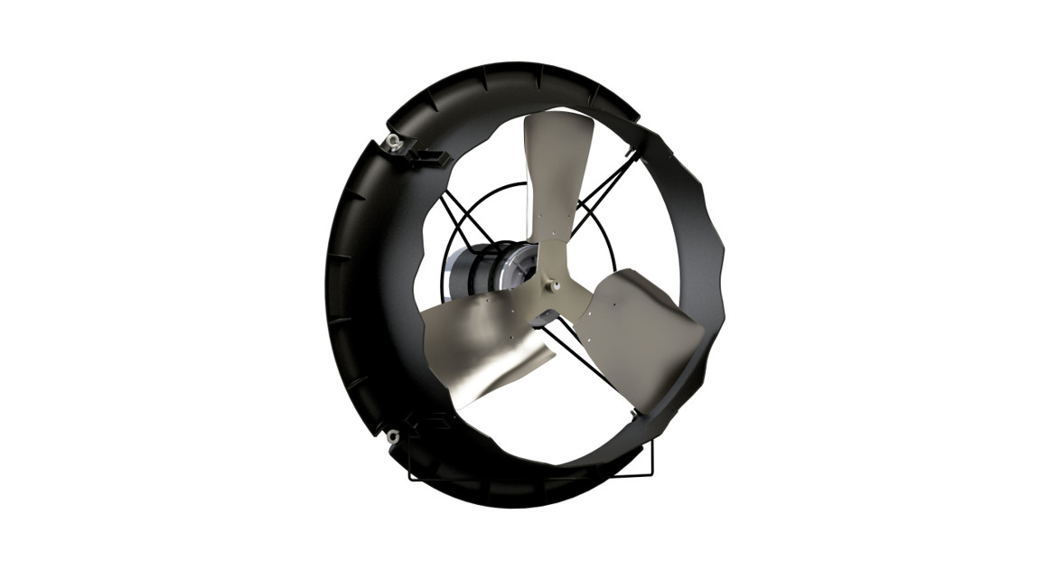
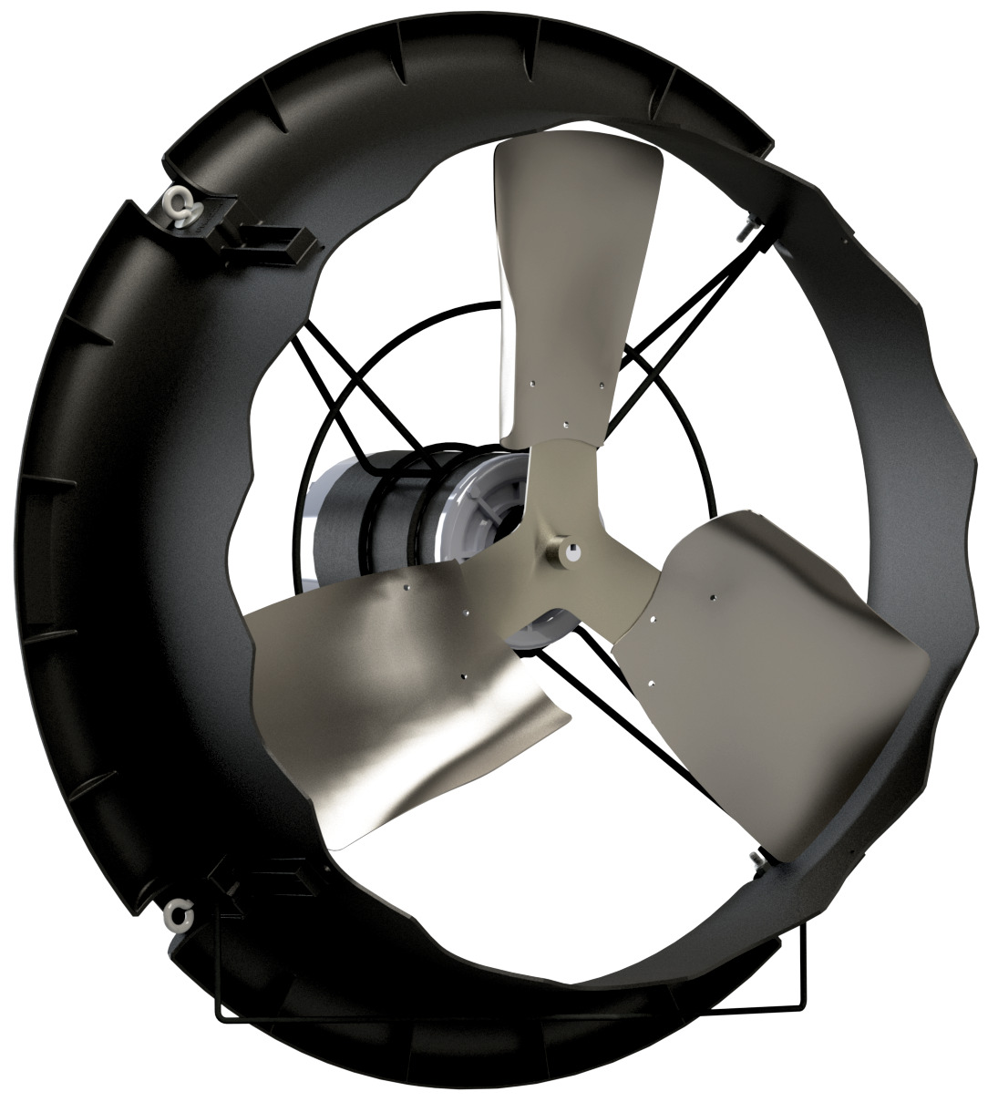
![]() CXCirculation Fan with or without Guard 24” Fan*Patents Pending
CXCirculation Fan with or without Guard 24” Fan*Patents Pending
Instruction Manual
 CX24P1/CX24P3
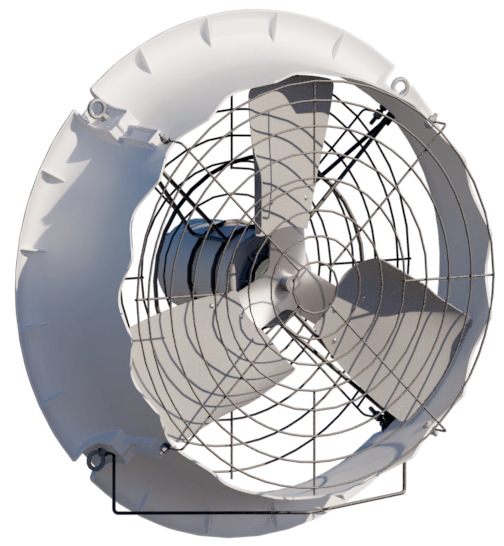
CX24PW1G/CX24PW3G
CX24 Circulation Fan – 24″Models: CX24P1 • CX24P3 • CX24P1G • CX24P3G • CX24PW1 • CX24PW3 • CX24P1WG • CX24P3WG
CX24 Circulation Fan 24” FansInstructions for Use and Maintenance
Thank You:Thank you for purchasing a Munters CX Circulation Fan. Munters equipment is designed to be the highest performing, highest quality equipment you can buy. With the proper installation and maintenance, it will provide many years of service.
Please Note:To achieve maximum performance and ensure long life from your Munters product it is essential that it be installedand maintained properly. Please read all instructions carefully before beginning installation.
Warranty:For Warranty claims information see the “Warranty Claims and Return Policy” form QM1021 available from theMunters Corporation office at 1-800-227-2376 or by e-mail at
Conditions and Limitations:
- Products and Systems involved in a warranty claim under the “Warranty Claims and Return Policy” shall have been properly installed, maintained and operated under competent supervision, according to the instructions provided by Munters Corporation.
- Malfunction or failure resulting from misuse, abuse, negligence, alteration, accident or lack of proper installation or maintenance shall not be considered a defect under the Warranty.
Unpacking the Equipment
Before beginning installation, check the overall condition of the equipment. Remove packing materials, and examine all components for signs of shipping damage. Any shipping damage is the customer’s responsibility and should be reported immediately to your freight carrier. Fan is shipped complete with all accessories.

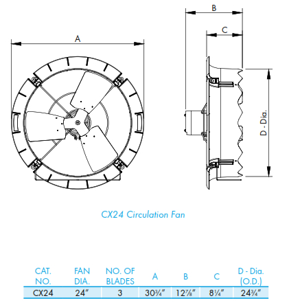
1.2 Fan DimensionsFan Specifi cations:Hertz: 60 50 – 60Voltage: 115/230VAC or 190 – 208-230/380 – 460VACPhase: 1 or 3
Installation Instructions
2.1 Fan InstallationStep 1For Horizontal Airflow attach chain to 2 of the Eye Bolts on the fan and then hang the fan from the truss. See Figure 1A. Chain and hanging hardware not provided. If it is desired to pull the fan up out of the way when not in use for cleaning, then attach a cable or rope to the Lift Bracket and use a winch or actuator to pull the fan up. See Figure 1B.
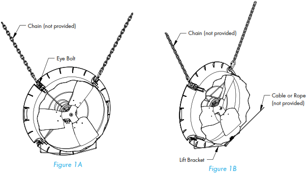
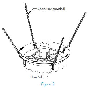
Step 2For Vertical Airflow attach chain to 4 of the Eye Bolts on the fan and then hang the fan from trusses. See Figure 2. Chain and hanging hardware not provided.
 IMPORTANT
If installing fans near heaters, it is recommended to install the CX24 Fan at a location far enough from heaters that will give a maximum temperature of 150°F. This should be approximately 2-3 ft. from the heater.
2.2 Optional Guard Installation
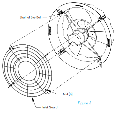
Step 3The Inlet Guard is the one with the large inner hole to go over the motor. With the eyelets on the guard pointing into the fan slip the eyelets over the shaft of the Eye Bolts and fasten using (4) Nuts [B].
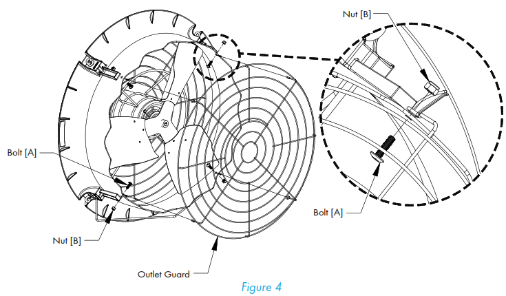
Step 4The Outlet Guard is the one with the small inner hole. With the eyelets on the guard pointing toward the fan, align the eyelets with the holes in orifice on the outside of the fasten using (4) Bolts [A] and Nuts [B]. The head of the bolt goes on the inside of the orifice and the nut goes on the outside. See Figure 4.
Electrical Wiring
All wiring should be installed in accordance with National, State, and Local electrical codes. Fans used to ventilate livestock buildings or other rooms where continuous air movement is essential should be connected to individual electrical circuits, with a minimum of two circuits per room. For electrical connection requirements, refer to the diagram on the motor nameplate and to the information enclosed with the Munters environmental control to be used. After wiring check for proper motor rotation.
Single Phase Fans: motor overload protection should be provided for each fan. A Circuit Breaker Switch or slow blow motor type fuses must be used, See Figure 5A. See form QM1400 for the proper size.
Three Phase Fans: motor overload protection should be provided for each fan. A three-pole motor starter or slow blow motor fuses must be used. See Figure 5B.
If a frequency drive (inverter) is used, confirm that motors are rated for inverter duty at the voltage used. A shielded power cable between frequency drive and each motor is highly recommended. Installation of line reactors is recommended to reduce voltage spikes and harmonic distortion. Supplemental motor overload protection is also recommended.
NOTE: A safety cut-off switch should be located adjacent to each fan.
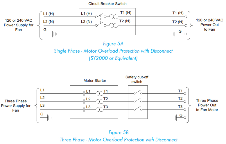
NOTE: Information in parenthesis refers to 120 VAC control.
KEY:
| L1=Line 1 | H=Hot |
| L2=Line 2 | N=Neutral |
| L3=Line 3 | G=Ground |
3.1 Recommended Wire Routing:As the power cable exits the back of motor form a drip loop and then run power cable up along leg of the motor mount and “Zip” tie the cable to leg to prevent the cable from getting tangled. See Figure 6. Then run the cable out the back of fan to the circuit breaker or control panel.

Figure 6
Three Phase Fans:1) The use of a quality frequency drive and the installation of line reactors is recommended to reduce voltage spikes and harmonic distortion.2) Minimum operating frequency of 30 Hz.3) Will require three-pole contractors with overload protection (by others).
Operation
4.1 Operation
| INITIAL START-UP: With electrical power off, verify that the fan propeller turns freely and that all fasteners are secure. Turn on electrical power and confirm that the fan operates smoothly. | |
| ADJUSTMENTS: Set the fan control to the temperature shown on your ventilation system drawing, or to a value that will provide the desired environmental conditions.
|
|
| Single Phase Fans: When variable speed controls are used, the fan’s idle speed will needto be set to the recommended minimum airflow rate. Refer to the procedures included witheach control. The table below provides airflow rates at various propeller speeds for fanswired for 240 VAC. |
Maintenance
5.1 Maintenance
The following inspection and cleaning procedures should be performed monthly:
| 1) INSPECT PROPELLER: Check that propeller is secure on motor shaft and thatthere are no signs of damage. The blades are of a self-cleaning design and shouldnot require maintenance. | |
| 2) CLEAN regularly for best results:• FAN MOTOR: Remove any dust accumulation from motor using a brush orcloth. (DO NOT use a pressure washer). A clean motor will run cooler and lastlonger. At the same time, verify that the motor is secure in its mount.• GUARD: Clean any dust or feathers from fan guards using a brush. Dirtyguards can reduce airflow. | |
| 3) CHECK FASTENERS: For safety, all fasteners should be inspected 1 month afterinitial operation and yearly thereafter. Tighten any loose connections. |
4) INSPECT FAN CONTROL: With power disconnected, inspect all electrical connections. Wiring should be secure and in good condition. Remove any dust build-up from control case and sensor using a soft brush or cloth. NEVER CLEAN ELECTRICAL EQUIPMENT WITH A PRESSURE WASHER!
Troubleshooting
6.1 Troubleshooting
| SYMPTOM | POSSIBLE CAUSES | CORRECTIVE ACTION | ||
| Fan Not Operating | 1. | Fan control set above room
temperature |
1. | Set to a lower temperature |
| 2. | Replace fuse or reset breaker | |||
| 2. | Blown fuse or open circuit breaker | 3. | Realign motor in fan housing | |
| 3. | Propeller blade contacting fan housing | 4. | Repair or replace control | |
| 4. | Fan control defective | 5. | Repair or replace motor | |
| 5. | Motor defective | |||
| Fan Operating-
Insufficient Airflow |
1. | Variable speed control improperly
adjusted |
1. | See Operation, Step 2 for adjustment guidelines |
| 2. | Clean guard | |||
| 2. | Guard dirty | |||
| Excessive Noise | 1. | Propeller blade contacting fan housing | 1. | Sand fan housing to remove high spot |
| 2. | Motor bearing defective | 2. | Repair or replace motor bearings | |
| 3. | Frequency drive improperly adjusted | 3. | See operation, Step 2 for adjustments guidelines | |
| Excessive
Vibration |
1. | Motor lose on mount | 1. | Tighten fasteners |
| 2. | Propeller damaged | 2. | Replace propeller | |
| 3. | Motor shaft bent | 3. | Repair or replace motor | |
| Fan never turns off | 1. | Override thermostat set incorrectly | 1. | Set to the correct temperature |
| 2. | Control set for continuous operation | 2. | Set speed control correctly |
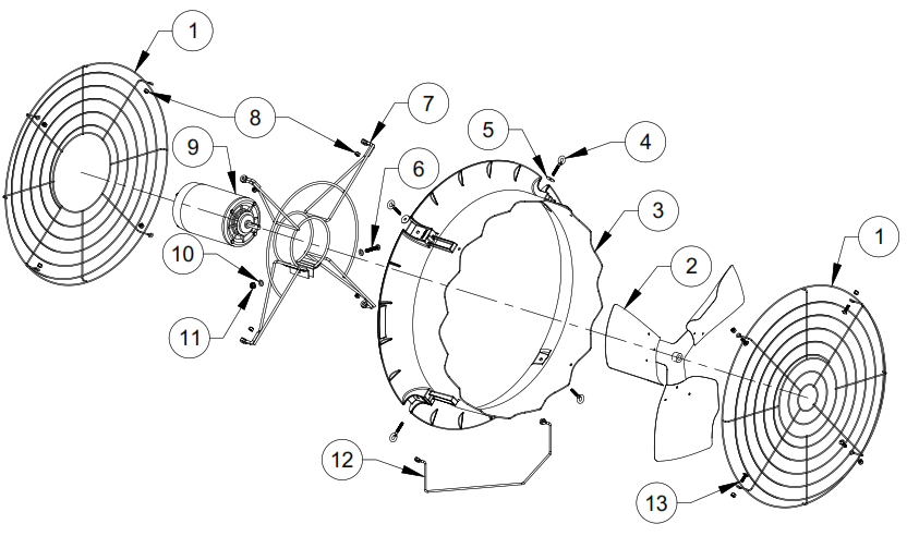
Exploded View
|
Item |
Catalog No. |
Description |
Qty. |
| 1 | FH1624 | Guard Inlet/Outlet Pair, PWDR CTD (Guard Kit) | 1 |
| 2 | FP1724 | Propeller, 24”DD, 3-Blade, CX24, GZ | 1 |
| 3 | FH4224B | Orifice Panel, 24″ CX Fan, PP, BLK | 1 |
| FH4224W | Orifice Panel, 24″ CX Fan, PP, WHT | 1 | |
| 4 | KS2757 | ¼”-20 x 2.5″ Closed Eye Bolt, SS | 4 |
| 5 | KW3012 | ¼” x 1″ O.D. Flat Washer, SS | 2 |
| 6 | KS1029 | 7⁄₁₆”-18 x 1.75″ Hex Head Bolt, SS | 1 |
| 7 | FH2524 | Motor Mount, 24″ CX Fan, PWDR CTD | 1 |
| 8 | KN1705 | ¼”-20 Nylock Nut, SS (Fan/Guard Kit) | 4/8 |
| 9 | FM1108 | 24” DD, Motor, ¹⁄₃ HP, 1075 RPM, 48 Fr., 1 ph., 115/230V | 1 |
| FM1074 | 24” DD, Motor, ¹⁄₃ HP, 1140 RPM, 48 Fr., 3 ph., 230/460V | ||
| 10 | KW3004 | 7⁄₁₆” Narrow Type-A Flat Washer, SS | 2 |
| 11 | KN0704 | 7⁄₁₆”-18 Hex, Serrated Flange Nut, SS | 1 |
| 12 | FH1324 | Lift Bracket, 2 Point Conn,CX24 Fan, PWDR CTD | 1 |
| 13 | KS0650 | 1⁄4”-20 x ⁷⁄₈” Truss Head Bolt, SS (Guard Kit) | 4 |
‘CX’ Fans are developed and produced by Munters Corporation, Lansing, Michigan U.S.A. 1-800-227-2376
Munters Europe AB, Isafjordsgatan 1, P.O. Box 1150, SE-164 26 Kista, Sweden. Phone +46 08 626 63 00, Fax +46 8 754 56 66.Munters Corporation 2691 Ena Drive Lansing, MI 48917 U.S.A. Phone +1 800-227-2376, Fax +1 517-676-7078www.munters.us
Australia Munters Pty Limited, Phone +61 2 6025 6422, Brazil Munters Brasil Industria e Comercio Ltda, Phone +55 41 3317 5050, Canada/US Munters Corporation Lansing, MI Phone +1 517 676 7070, China Munters Air Treatment Equipment (Beijing) Co. Ltd, Phone +86 10 80 481 121, Denmark Munters A/S, Phone +45 9862 3311, India Munters India, Phone +91 20 3052 2520, Indonesia Munters, Phone +62 818 739 235, Italy Munters Italy S.p.A., Chiusavecchia, Phone +39 0183 52 11, Japan Munters K.K., Phone +81 3 5970 0021, Korea Munters Korea Co. Ltd., Phone +82 2 761 8701, Mexico Munters Mexico, Phone +52 818 262 54 00, Russia Munters AB, Phone +7 812 448 5740, Singapore Munters Pte Ltd., Phone +65 744 6828, South Africa and Sub-Sahara Countries Munters (Pty) Ltd., Phone +27 11 997 2000, Spain Munters Spain S.A., Phone +34 91 640 09 02, Sweden Munters AB, Phone +46 8 626 63 00, Thailand Munters Co. Ltd., Phone +66 2 642 2670, Turkey Munters Form Endüstri Sistemleri A.Ş, Phone +90 322 231 1338, USA Munters Corporation Lansing, MI Phone +1 517 676 7070, Vietnam Munters Vietnam, Phone +84 8 3825 6838, Export & Other countries Munters Italy S.p.A., Chiusavecchia Phone +39 0183 52 11
References
[xyz-ips snippet=”download-snippet”]