
Munters Green RTU Configuration
Instruction Manual

Revision: N. 1.4 of 03.2021Product Software: N/A
This manual for use and maintenance is an integral part of the apparatus together with the attached technical documentation.
This document is destined for the user of the apparatus: it may not be reproduced in whole or in part, committed to computer memory as a file or delivered to third parties without the prior authorization of the assembler of the system.
Munters reserves the right to effect modifications to the apparatus in accordance with technical and legal developments.
1 Introduction
1.1 Disclaimer
Munters reserves the right to make alterations to specifications, quantities, dimensions etc. for production or other reasons, subsequent to publication. The information contained herein has been prepared by qualified experts within Munters. While we believe the information is accurate and complete, we make no warranty or representation for any particular purposes. The information is offered in good faith and with the understanding that any use of the units or accessories in breach of the directions and warnings in this document is at the sole discretion and risk of the user.
1.2 Introduction
Congratulations on your excellent choice of purchasing a Green RTU Units! In order to realize the full benefit from this product it is important that it is installed, commissioned and operated correctly. Before installation or using the units, this manual should be studied carefully. It is also recommended that it is kept safely for future reference. The manual is intended as a reference for installation, commissioning and day-to-day operation of the Munters Controllers.
1.3 Notes
Date of release: May 2020
Munters cannot guarantee to inform users about the changes or to distribute new manuals to them. NOTE All rights reserved. No part of this manual may be reproduced in any manner whatsoever without the expressed written permission of Munters. The contents of this manual are subject to change without notice.
2 Configuration
This manuals contains the information needed for a basic setup. For more detailed information go to Munters’ on-line manual library. This document lists the basic steps to be done when installing Munters Green RTU Units. For complete information on the products and their installation, refer to the following documents:
- Serial Transmitter Module Installation Manual (P/N 116809)
- Radio Repeater Module Installation Manual (P/N 116810)
- RTU RX Module Installation Manual (P/N 116812)
- G5 RX Module Programming Manual (P/N 116811)

2.1 Introduction
The following document describes how to set up the Serial Transmitter Module. In doing so, you can define exactly how the Green Field Controller manages all valves.

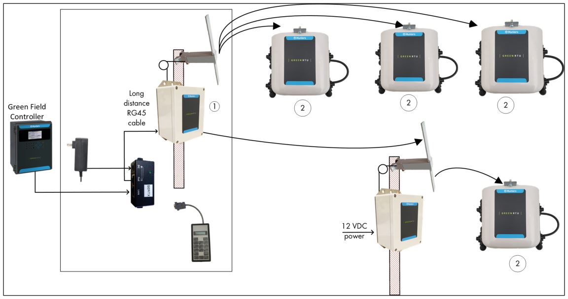
Figure 5: Kit and RTU Modules Components (see the following table)
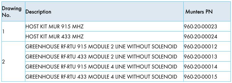
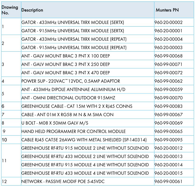
 Figure 6: Spare Parts (see the following table)
2.2 Controller — Transmitter Setup
- Controller Setup
- Wiring
2.2.1 CONTROLLER SETUP
Observe the following points when setting up the Green Field Controller and G5 Transmitter.
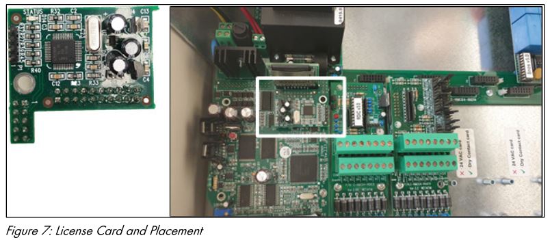
- The Green Field Controller must have a License Card.
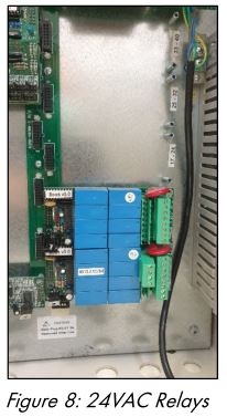
- The Controller can have 24VAC local relays (for pumps, fertigation, filters, etc.). Figure 8 shows 16 local 24VAC outputs; remote outputs start from relay 17.
2.2.2 WIRING
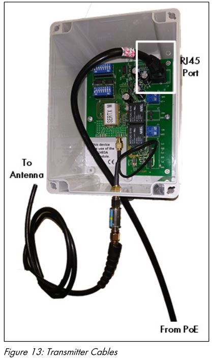
- Connect the Controller to the Transmitter as shown in the following diagram.
 Figure 13 displays
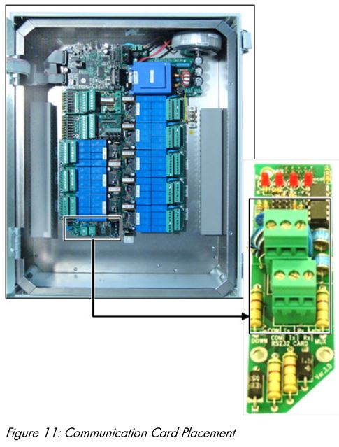
- The only connection that requires wiring is the Green Field Communication Card. Wire this card to the RJ-45 Male cable as shown in Figure 10.
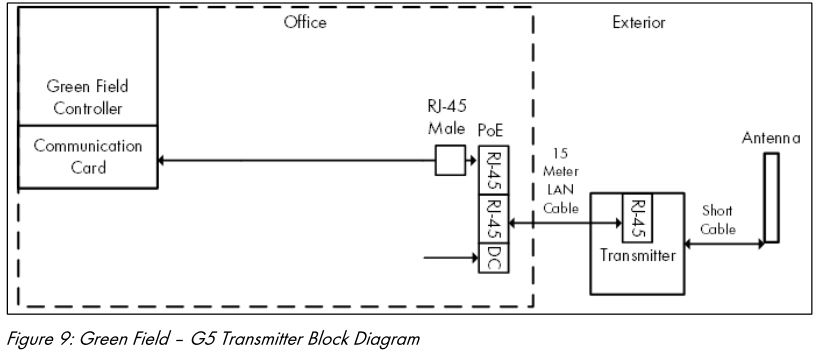 Figure 13 displays
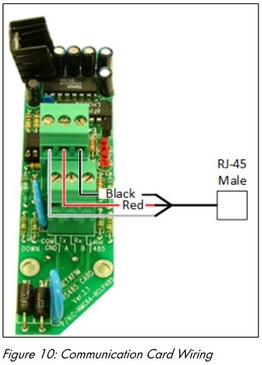
- Use the PoE device to connect the RJ45 cables as detailed below:
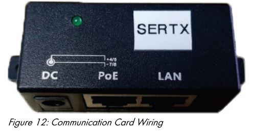
- LAN: RJ45 cable from the Green Field Controller
- PoE: RJ45 cable to the Transmitter
- 12 VDC: Power cable
CAUTIONDisconnecting the power supply means that wireless connectivity ceases! Ensure that the 12VDC power cable is secured and cannot be disconnected while the system is operating!
- Connect the antenna cable (Figure 13).
2.3 Setting up the G5 Transmitter
 2.3 Setting up the G5 Transmitter
- Mounting the Transmitter
- Defining the Dipswitches
2.3.1 MOUNTING THE TRANSMITTER
- Installing and mounting the unit: Refer to the Serial Transmitter Module Installation Guide.
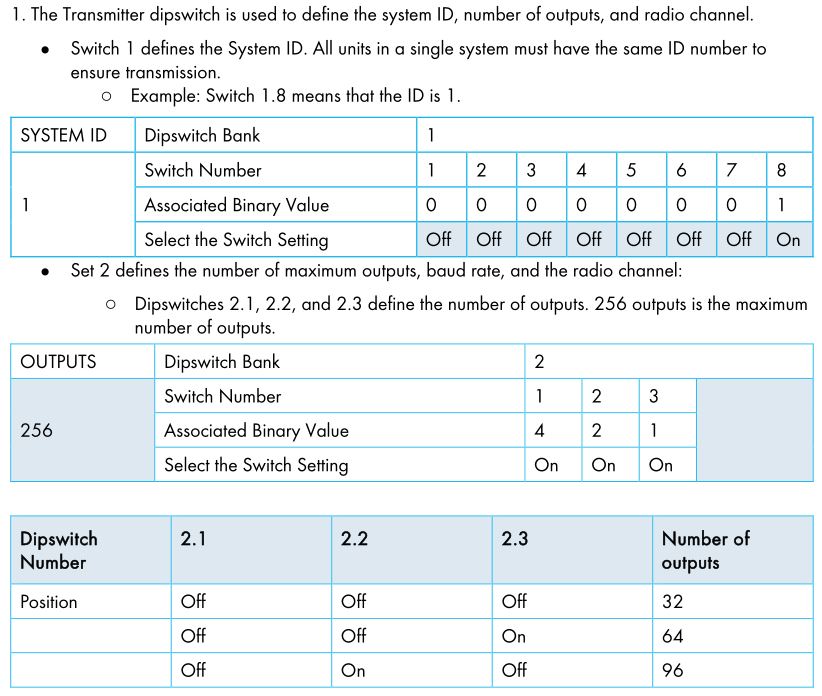
2.3.2 DEFINING THE DIPSWITCHES


2.4 Setting Up the Green RTU
- Mounting the Green RTU
- Programing
2.4.1 MOUNTING THE GREEN RTU
- Refer to the RTU RX Module Installation Manual for detailed instructions on mounting and powering the unit and on connecting it to output devices.
2.4.2 PROGRAMING
- Refer to the G5 RX Module Programming Manual for detailed instructions on using the programmer.
Using the Hand Held Programmer, define the Green RTU communication parameters.
- Connect the Programmer to the Green RTU.
- Press the Red Button on the DB9 cover for two seconds.
- Define:
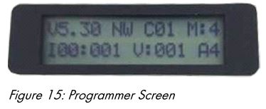
- NW: Communication wireless protocol (read only)
- CO1: This is the channel o I00:XXX is the system ID, in which X must match the transmitter System ID.
- M is the number of receiver outputs. In the above figure, the receiver controls four outputs.
- V:00X: This number defines which outputs are activated. Each receiver controls four consecutive outputs. X is the number of the first valve in the series. For example, if X is 9, the GTU RX controls valves 9, 10, 11, and 12.
2.5 Green Field Controller Set Up
- Communication Protocol
- Defining Remote Relays
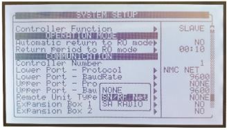
2.5.1 COMMUNICATION PROTOCOL
The following procedure details how to define the Green Field Controller communication protocol.
- On the Green Field screen, go to Setup > System Setup.
- Scroll down to Communication.
- Define the Remote Unit Type as SN/SF NET. NOTE All remote units connected to the Green Field Controller must use be connected via radio.
- Define the relevant parameters (baud rate).
- Apply power to both units. After ten seconds, “Host Unit Error” should appear on the Green Field Controller screen.
 NOTE All remote units connected to the Green Field Controller must use be connected via radio.
2.5.2 DEFINING REMOTE RELAYS
- On the Green Field screen, go to Installation > Device Layout.
- Relays 17 20 are remote unit relays. Define them as valves.
- Repeat for each Green RTU.
2.6 Trouble Shooting and Testing
Problem: Valve definition does not match dipswitch definition.
Explanation: Dipswitches define the maximum number of valves. If the Hand Held Programmer defines valves about this range, an error is recorded.
For exampleDipswitches 2.1, 2.2, and 2.3 are in the Off position; this enables up to 32 valves. If the Programmer defines V:032, valve 32 is turned on, but valves 33, 34, and 35 are errors.
3 Warranty
Warranty and technical assistanceMunters products are designed and built to provide reliable and satisfactory performance but cannot be guaranteed free of faults; although they are reliable products they can develop unforeseeable defects and the user must take this into account and arrange adequate emergency or alarm systems if failure to operate could cause damage to the articles for which the Munters plant was required: if this is not done, the user is fully responsible for the damage which they could suffer.
Munters extends this limited warranty to the first purchaser and guarantees its products to be free from defects originating in manufacture or materials for one year from the date of delivery, provided that suitable transport, storage, installation and maintenance terms are complied with. The warranty does not apply if the products have been repaired without express authorisation from Munters, or repaired in such a way that, in Munters’ judgement, their performance and reliability have been impaired, or incorrectly installed, or subjected to improper use. The user accepts total responsibility for incorrect use of the products.
The warranty on products from outside suppliers fitted to the Green RTU units, (for example cables, power supplies, etc.) is limited to the conditions stated by the supplier: all claims must be made in writing within eight days of the discovery of the defect and within 12 months of the delivery of the defective product. Munters has thirty days from the date of receipt in which to take action, and has the right to examine the product at the customer’s premises or at its own plant (carriage cost to be borne by the customer).
Munters at its sole discretion has the option of replacing or repairing, free of charge, products which it considers defective, and will arrange for their despatch back to the customer carriage paid. In the case of faulty parts of small commercial value which are widely available (such as bolts, etc.) for urgent despatch, where the cost of carriage would exceed the value of the parts, Munters may authorise the customer exclusively to purchase the replacement parts locally; Munters will reimburse the value of the product at its cost price.
Munters will not be liable for costs incurred in demounting the defective part, or the time required to travel to site and the associated travel costs. No agent, employee or dealer is authorised to give any further guarantees or to accept any other liability on Munters’ behalf in connection with other Munters products, except in writing with the signature of one of the Company’s Managers.
WARNING: In the interests of improving the quality of its products and services, Munters reserves the right at any time and without prior notice to alter the specifications in this manual.
The liability of the manufacturer Munters ceases in the event of:
- dismantling the safety devices;
- use of unauthorised materials;
- inadequate maintenance;
- use of non-original spare parts and accessories.
Barring specific contractual terms, the following are directly at the user’s expense:
- preparing installation sites;
- providing an electricity supply (including the protective equipotential bonding (PE) conductor, in accordance with CEI EN 60204-1, paragraph 8.2), for correctly connecting the equipment to the mains electricity supply;
- providing ancillary services appropriate to the requirements of the plant on the basis of the information supplied with regard to installation;
- tools and consumables required for fitting and installation;
- lubricants necessary for commissioning and maintenance.
It is mandatory to purchase and use only original spare parts or those recommended by the manufacturer.
Dismantling and assembly must be performed by qualified technicians and according to the manufacturer’s instructions.
The use of non-original spare parts or incorrect assembly exonerates the manufacturer from all liability.
Requests for technical assistance and spare parts can be made directly to the nearest Munters office. A full list of contact details can be found on the back page of this manual.
Munters Israel18 HaSivim StreetPetach-Tikva 49517, IsraelTelephone: +972-3-920-6200Fax: +972-3-924-9834
![]()
Australia Munters Pty Limited, Phone +61 2 8843 1594,
Brazil Munters Brasil Industria e Comercio Ltda, Phone +55 41 3317 5050,
Canada Munters Corporation Lansing, Phone +1 517 676 7070,
China Munters Air Treatment Equipment (Beijing) Co. Ltd, Phone +86 10 80 481 121,
Denmark Munters A/S, Phone +45 9862 3311,
India Munters India, Phone +91 20 3052 2520,
Indonesia Munters, Phone +62 818 739 235,
Israel Munters Israel Phone +972-3-920-6200,
Italy Munters Italy S.p.A., Chiusavecchia, Phone +39 0183 52 11,
Japan Munters K.K., Phone +81 3 5970 0021,
Korea Munters Korea Co. Ltd., Phone +82 2 761 8701,
Mexico Munters Mexico, Phone +52 818 262 54 00,
Singapore Munters Pte Ltd., Phone +65 744 6828,
South Africa and Sub-Sahara Countries Munters (Pty) Ltd., Phone +27 11 997 2000,
Spain Munters Spain S.A., Phone +34 91 640 09 02,
Sweden Munters AB, Phone +46 8 626 63 00,
Thailand Munters Co. Ltd., Phone +66 2 642 2670,
Turkey Munters Form Endüstri Sistemleri A., Phone +90 322 231 1338,
USA Munters Corporation Lansing, Phone +1 517 676 7070,
Vietnam Munters Vietnam, Phone +84 8 3825 6838,
Export & Other countries Munters Italy S.p.A., Chiusavecchia Phone +39 0183 52 11
References
[xyz-ips snippet=”download-snippet”]