RJB-4Manual for use and maintenance
RJB-4
![]()
Ag/MIS/UmGB-2186-05/14 Rev 1.1P/N: 116252
Revision: N.1.1 of 02.2021 Ag/MIS/UmGB-2186-05/14 rev 2.7 (MIS)Product Software: N/A
This manual for use and maintenance is an integral part of the apparatus together with the attached technical documentation. This document is destined for the user of the apparatus: it may not be reproduced in whole or in part, committed to computer memory as a file or delivered to third parties without the prior authorization of the assembler of the system. Munters reserves the right to effect modifications to the apparatus in accordance with technical and legal developments.
Installation
Munters RJB-4 (RJB-4) enables connecting up to 16 load cells to a single RSW-2 Controller or a Platinum Controller. This document details the wiring procedures between the scales and the RJB-4, and between the RJB-4 and the RSW-2.The RJB-4 comes with:
- AWG 14 (thick) cable used to ground the silo (Figure 5)
- AWG 22 (thin) cable for wiring the RJB-4 to a grounding rod (Figure 6)
Connecting Silo Load Cells to the RJB-4Described below are the wiring connections between the load cells to the RJB-4 Junction Box, and from the junction box to the Silo Weighing Controller (RSW-2).Load cell part numbers:
- RSLC-04: 911-03-XXXXX
- RSLC-10: 911-04-XXXXX
- RSLC-25: 911-05-XXXXX
NOTE: The RSLC supports RSW-2 boards, version 7.0 and above.
- Each load cell has a 4-wire shielded cable.o Connect each load cell to the RJB-4 double connector with exactly the colors that written on the RJB-4 PCB board.o Figure 1 illustrates the connections made to a load cell.
Cable Board White White Red Red Black Black Green Green o Connect the shield wire to the shield input.
- Key:1: Shield wire

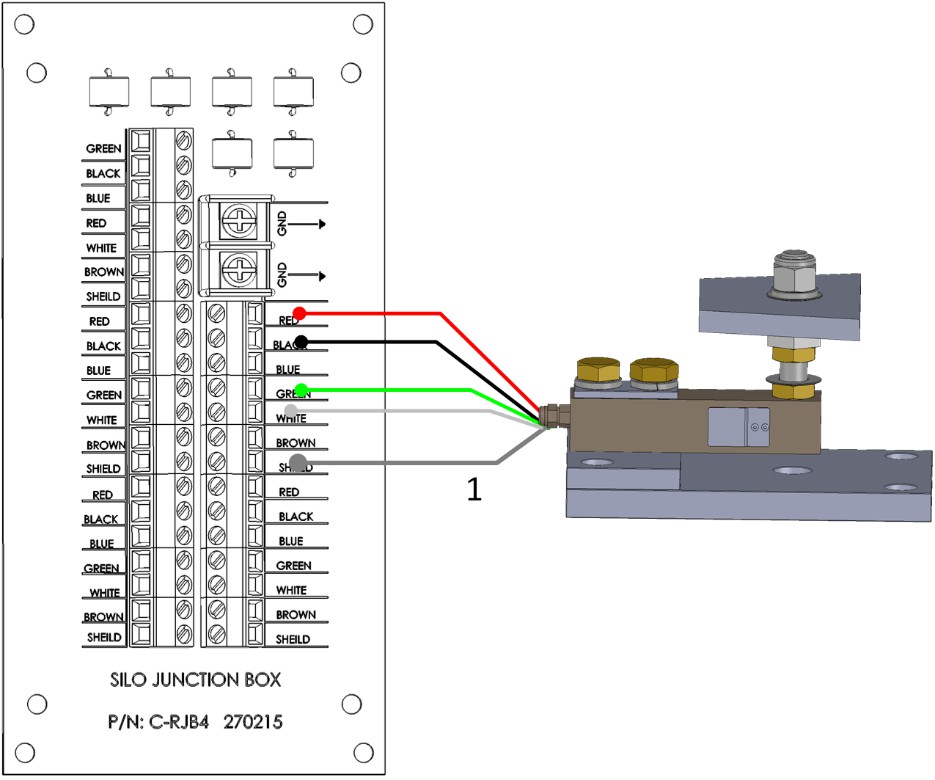
Figure1: RJB-4 to Load Cell Wiring Diagram2. Repeat for each load cell.NOTE: The RJB-4 can support more than one load cell on each terminal. To connect more than four load cells to the RJB-4, place a second set of load cell wires into each terminal load cell block.Figure 2: illustrates four load cells connected to the RJB-4.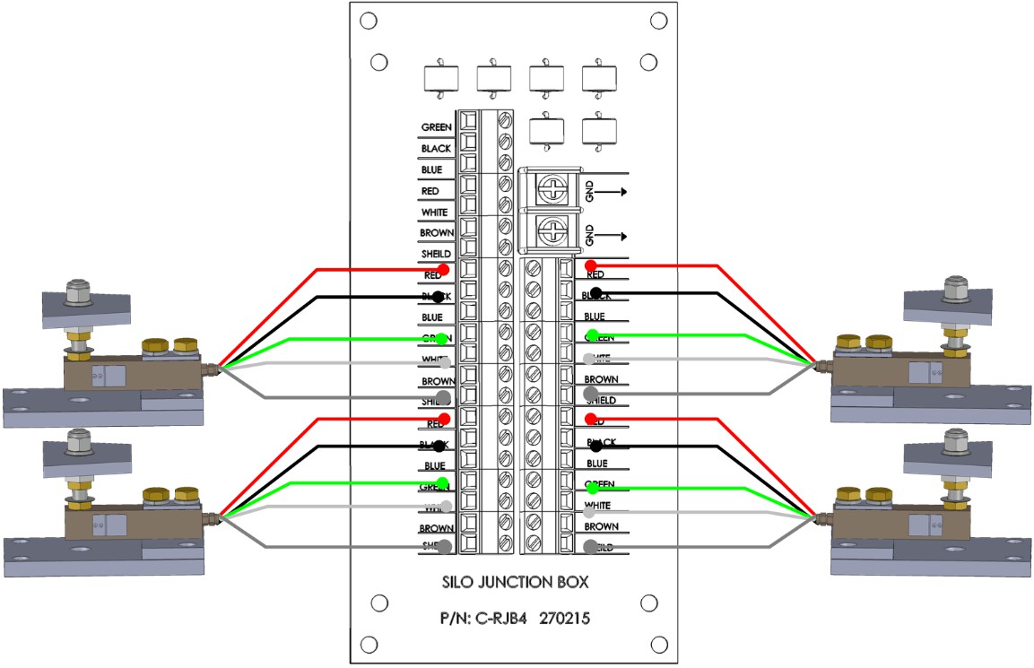 Figure 2: RJB-4 Connected to Four Silos3. The RSW-2 cell has a 4-wire shielded cable. Run these wires from the RSW-2 Silo A terminal block to the RJB-4 controller terminal block; attach each wire to the input slot with same color. For example, connect the red wire to the red input slot. Figure 3 illustrates the wiring.
| Cable | Board |
| White | White |
| Red | Red |
| Black | Black |
| Green | Green |
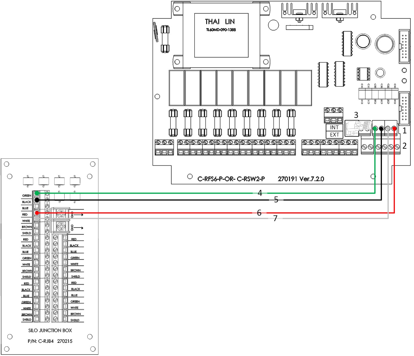 Figure 3: RJB-4 to RSW-2 Wiring• Key:o 1: Silo 1o 2: Silo 2o 3: Place two jumpers on INTo 4: Green wireo 5: Black wireo 6: Red wireo 7: White wire
NOTE: There can be up to 100 meters of the supplied black/gray cable between the RSW and the RJB. Figure 4 illustrates a complete Platinum RJB-4 system.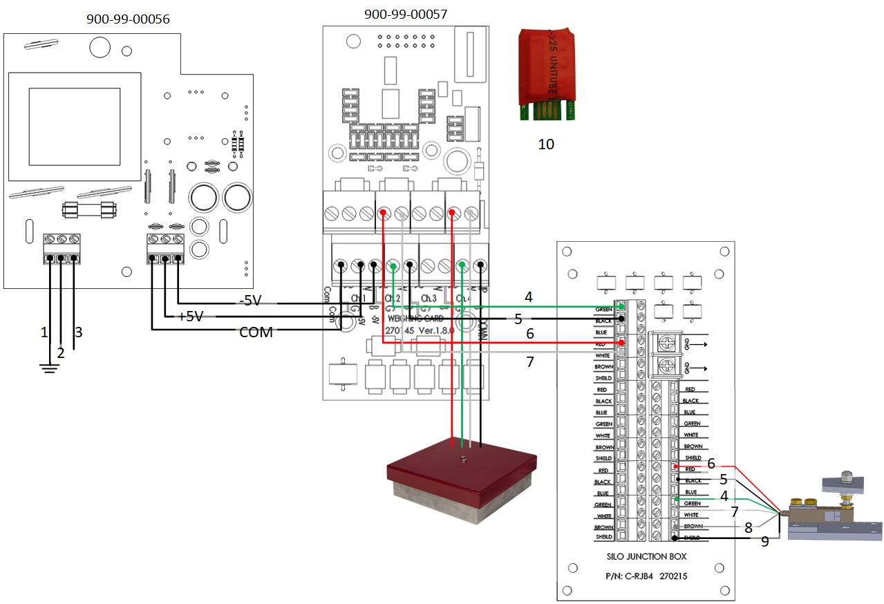 Figure 4: RJB-4 Wired to Platinum
- Key:
• 1: Ground • 6: Green wire • 2: Neutral (USA: L1) • 7: Black wire • 3: Phase (USA: L2) • 8: Brown wire • 4: Red wire • 9: Shield wire • 5: White wire • 10: Software plug
GroundingProper grounding consists of two steps.
- Use the AWG 22 cable to connect the RJB-4 to a grounding rod.Figure 5: RJB-4 Connected to Grounding RodNOTE: Less than 5 ohms is considered a good ground.
- Use the AWG 14 cable to connect the silo to a grounding rod.Figure 6: Grounding
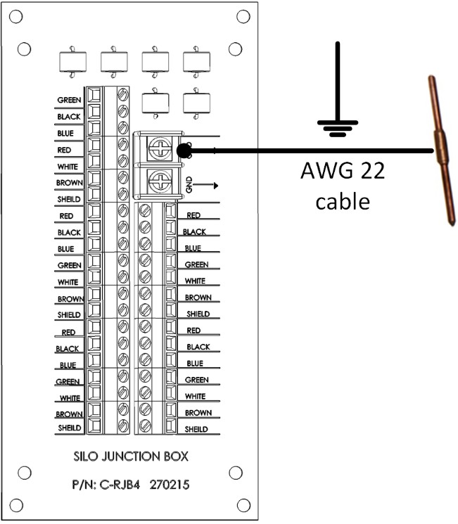 Figure 5: RJB-4 Connected to Grounding RodNOTE: Less than 5 ohms is considered a good ground.
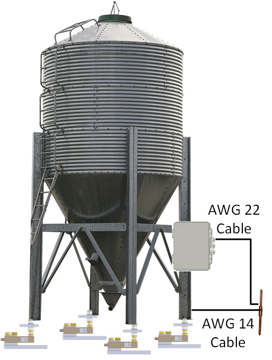 Figure 6: Grounding
Powering the RJB-4
- If there are six or less load cells connected to the RJB, no external power is required.
- If there are more than six load cells connected to the RJB, external power is required.CAUTIONVerify that the RJB-4 is properly grounded to one of the ground terminals. The RJB-4 is powered via the RSW-2 or the Platinum. For detailed wiring, information refer to the respective manual.
Scale CalibrationCalibrate the RJB-4 before using the unit. For detailed calibration instructions, refer to the RSW-2 or Platinum manuals.
Environmental Protection Recycle raw materials instead of disposing of as waste. The controller, accessories, and packaging should be sorted for environmental-friendly recycling. The plastic components are labeled for categorized recycling.
Warranty
Warranty and technical assistanceMunters products are designed and built to provide reliable and satisfactory performance but cannot be guaranteed free of faults; although they are reliable products they can develop unforeseeable defects and the user must take this into account and arrange adequate emergency or alarm systems if failure to operate could cause damage to the articles for which the Munters plant was required: if this is not done, the user is fully responsible for the damage which they could suffer.
Munters extends this limited warranty to the first purchaser and guarantees its products to be free from defects originating in manufacture or materials for one year from the date of delivery, provided that suitable transport, storage, installation and maintenance terms are complied with. The warranty does not apply if the products have been repaired without express authorization from Munters, or repaired in such a way that, in Munters’ judgment, their performance and reliability have been impaired, or incorrectly installed, or subjected to improper use. The user accepts total responsibility for incorrect use of the products.
The warranty on products from outside suppliers fitted to the Junction Box, (for example cables, weights, etc.) is limited to the conditions stated by the supplier: all claims must be made in writing within eight days of the discovery of the defect and within 12 months of the delivery of the defective product. Munters has thirty days from the date of receipt in which to take action, and has the right to examine the product at the customer’s premises or at its own plant (carriage cost to be borne by the customer).
Munters at its sole discretion has the option of replacing or repairing, free of charge, products which it considers defective, and will arrange for their dispatch back to the customer carriage paid. In the case of faulty parts of small commercial value which are widely available (such as bolts, etc.) for urgent dispatch, where the cost of carriage would exceed the value of the parts, Munters may authorize the customer exclusively to purchase the replacement parts locally; Munters will reimburse the value of the product at its cost price.
Munters will not be liable for costs incurred in demounting the defective part, or the time required to travel to site and the associated travel costs. No agent, employee or dealer is authorized to give any further guarantees or to accept any other liability on Munters’ behalf in connection with other Munters products, except in writing with the signature of one of the Company’s Managers.
WARNING: In the interests of improving the quality of its products and services, Munters reserves the right at any time and without prior notice to alter the specifications in this manual.The liability of the manufacturer Munters ceases in the event of:
- dismantling the safety devices;
- use of unauthorized materials;
- inadequate maintenance;
- use of non-original spare parts and accessories.
Barring specific contractual terms, the following are directly at the user’s expense:
- preparing installation sites;
- providing an electricity supply (including the protective equipotential bonding (PE) conductor, in accordance with CEI EN 60204-1, paragraph 8.2), for correctly connecting the equipment to the mains electricity supply;
- providing ancillary services appropriate to the requirements of the plant on the basis of the information supplied with regard to installation;
- tools and consumables required for fitting and installation;
- lubricants necessary for commissioning and maintenance.
It is mandatory to purchase and use only original spare parts or those recommended by the manufacturer. Dismantling and assembly must be performed by qualified technicians and according to the manufacturer’s instructions.
The use of non-original spare parts or incorrect assembly exonerates the manufacturer from all liability. Requests for technical assistance and spare parts can be made directly to the nearest Munters office. A full list of contact details can be found on the back page of this manual.
Munters Israel:18 HaSivim StreetPetach-Tikva 49517, IsraelTelephone: +972-3-920-6200Fax: +972-3-924-9834[email protected]
![]() www.munters.comAustralia Munters Pty Limited, Phone +61 2 8843 1594, Brazil Munters Brasil Industria e Comercio Ltda, Phone +55 41 3317 5050, Canada Munters Corporation Lansing, Phone +1 517 676 7070, China Munters Air Treatment Equipment (Beijing) Co. Ltd, Phone +86 10 80 481 121, Denmark Munters A/S, Phone +45 9862 3311, India Munters India, Phone +91 20 3052 2520, Indonesia Munters, Phone +62 818 739 235, Israel Munters Israel Phone +972-3-920-6200, Italy Munters Italy S.p.A., Chiusavecchia, Phone +39 0183 52 11, Japan Munters K.K., Phone +81 3 5970 0021, Korea Munters Korea Co. Ltd., Phone +82 2 761 8701, Mexico Munters Mexico, Phone +52 818 262 54 00, Singapore Munters Pte Ltd., Phone +65 744 6828, South Africa and Sub-Sahara Countries Munters (Pty) Ltd., Phone +27 11 997 2000, Spain Munters Spain S.A., Phone +34 91 640 09 02, Sweden Munters AB, Phone +46 8 626 63 00, Thailand Munters Co. Ltd., Phone +66 2 642 2670, Turkey Munters Form Endüstri Sistemleri A., Phone +90 322 231 1338, USA Munters Corporation Lansing, Phone +1 517 676 7070, Vietnam Munters Vietnam, Phone +84 8 3825 6838, Export & Other countries Munters Italy S.p.A., Chiusavecchia Phone +39 0183 52 11
www.munters.comAustralia Munters Pty Limited, Phone +61 2 8843 1594, Brazil Munters Brasil Industria e Comercio Ltda, Phone +55 41 3317 5050, Canada Munters Corporation Lansing, Phone +1 517 676 7070, China Munters Air Treatment Equipment (Beijing) Co. Ltd, Phone +86 10 80 481 121, Denmark Munters A/S, Phone +45 9862 3311, India Munters India, Phone +91 20 3052 2520, Indonesia Munters, Phone +62 818 739 235, Israel Munters Israel Phone +972-3-920-6200, Italy Munters Italy S.p.A., Chiusavecchia, Phone +39 0183 52 11, Japan Munters K.K., Phone +81 3 5970 0021, Korea Munters Korea Co. Ltd., Phone +82 2 761 8701, Mexico Munters Mexico, Phone +52 818 262 54 00, Singapore Munters Pte Ltd., Phone +65 744 6828, South Africa and Sub-Sahara Countries Munters (Pty) Ltd., Phone +27 11 997 2000, Spain Munters Spain S.A., Phone +34 91 640 09 02, Sweden Munters AB, Phone +46 8 626 63 00, Thailand Munters Co. Ltd., Phone +66 2 642 2670, Turkey Munters Form Endüstri Sistemleri A., Phone +90 322 231 1338, USA Munters Corporation Lansing, Phone +1 517 676 7070, Vietnam Munters Vietnam, Phone +84 8 3825 6838, Export & Other countries Munters Italy S.p.A., Chiusavecchia Phone +39 0183 52 11
Ag/MIS/UmGB-2186-05/14 rev 1.1© Munters AB, 2018
References
[xyz-ips snippet=”download-snippet”]