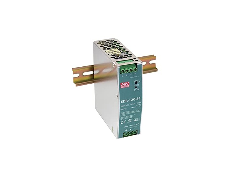
MW MEAN WELL 120W Single Output Industrial DIN RAIL User Guide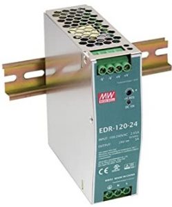
Features
- Universal AC input / Full range.
- Protections: Short circuit / Overload / Over voltage / Over temperature.
- Cooling by free air convection.
- Can be installed on DIN rail TS-35/7.5 or 15.
- UL 508 (industrial control equipment) approved.
- EN61000-6-2(EN50082-2) industrial immunity level.
- 100% full load burn-in test.
- 3 years warranty
Description
NDR-120 is one economical slim 120W DIN rail power supply series, adapt to be installed on TS-35/7.5 or TS-35/15 mounting rails. The body is designed 40mm in width, which allows space saving inside the cabinets. The entire series adopts the full range AC input from 90VAC to 264VAC and conforms to EN61000-3-2, the norm the European Union regulates for harmonic current.NDR-120 is designed with metal housing that enhances the unit’s power dissipation. With working efficiency up to 89%, the entire series can operate at the ambient temperature between -20°C and 70°C under air convection. It is equipped with constant current mode for over-load protection, fitting various inductive or capacitive applications. The complete protection functions and relevant certificates for industrial control apparatus (UL508, TUV EN62368-1, and etc.) make NDR-120 a very competitive power supply solution for industrial applications.
Model Encoding

Applications
- Industrial control system.
- Semiconductor fabrication equipment.
- Factory automation.
- Electro-mechanical apparatus
SPECIFICATION
| MODEL |
NDR-120-12 |
NDR-120-24 |
NDR-120-48 |
|
| OUTPUT |
DC VOLTAGE |
12V | 24V | 48V |
|
RATED CURRENT |
10A |
5V |
2.5V |
|
|
CURRENT RANGE |
0 ~ 10A | 0 ~ 5A |
0 ~ 2.5A |
|
|
RATED POWER |
120W |
120W |
120W |
|
|
RIPPLE & NOISE (max.) Note.2 |
100mVp-p |
120mVp-p |
150mVp-p |
|
|
VOLTAGE ADJ. RANGE |
12 ~ 14V |
24 ~ 28V |
48 ~ 55V |
|
|
VOLTAGE TOLERANCE Note.3 |
±2.0% | ±1.0% | ±1.0% | |
|
LINE REGULATION |
±0.5% |
±0.5% |
±0.5% |
|
|
LOAD REGULATION |
±1.0% |
±1.0% |
±1.0% |
|
|
SETUP, RISE TIME |
1200ms, 60ms/230VAC 2500ms, 60ms/115VAC at full load | |||
|
HOLD UP TIME (Typ.) |
16ms/230VAC 10ms/115VAC at full load | |||
| INPUT | VOLTAGE RANGE Note.6 | 90 ~ 264VAC 127 ~ 370VDC [DC input operation possible by connecting AC/L(+), AC/N(-)] | ||
| FREQUENCY RANGE | 47 ~ 63Hz | |||
|
EFFICIENCY (Typ.) |
85.5% |
88% |
89% |
|
|
AC CURRENT (Typ.) |
2.25A/115VAC 1.3A/230VAC | |||
|
INRUSH CURRENT (Typ.) |
20A/115VAC 35A/230VAC | |||
|
LEAKAGE CURRENT |
<1mA / 240VAC | |||
| PROTECTION |
OVERLOAD |
105 ~ 130% rated output power | ||
| Protection type : Constant current limiting, recovers automatically after fault condition is removed | ||||
|
OVER VOLTAGE |
14 ~ 17V |
29 ~ 33V |
56 ~ 65V |
|
| Protection type : Shut down o/p voltage, re-power on to recover | ||||
|
OVER TEMPERATURE |
Shut down o/p voltage, re-power on to recover | |||
| ENVIRONMENT |
WORKING TEMP. |
-20 ~ +70 (Refer to “Derating Curve”) ℃ | ||
|
WORKING HUMIDITY |
20 ~ 95% RH non-condensing | |||
|
STORAGE TEMP., HUMIDITY |
-40 ~ +85 , 10 ~ 95% RH ℃ | |||
|
TEMP. COEFFICIENT |
±℃ ℃ 0.03%/ (0 ~ 50 ) | |||
|
VIBRATION |
Component:10 ~ 500Hz, 2G 10min./1cycle, 60min. each along X, Y, Z axes; Mounting: Compliance to IEC60068-2-6 | |||
| SAFETY & EMC (Note 4) |
SAFETY STANDARDS |
UL508, TUV EN62368-1, approved;(meet EN60204-1) EAC TP TC 004 | ||
|
WITHSTAND VOLTAGE |
I/P-O/P:3KVAC I/P-FG:2KVAC O/P-FG:0.5KVAC | |||
|
ISOLATION RESISTANCE |
I/P-O/P, I/P-FG, O/P-FG:>100M Ohms / 500VDC / 25 / 70% RH ℃ | |||
|
EMC EMISSION |
Compliance to EN55032 (CISPR32), EN61204-3 Class B, EN61000-3-2,-3, EAC TP TC 020 | |||
|
EMC IMMUNITY |
Compliance to EN61000-4-2,3,4,5,6,8,11, EN55024, EN61000-6-2 (EN50082-2), EN61204-3, heavy industry level, criteria A, EAC TP TC 020 | |||
| OTHERS |
MTBF |
456.3K hrs min. MIL-HDBK-217F (25 ) ℃ | ||
|
DIMENSION |
40*125.2*113.5mm (W*H*D) | |||
|
PACKING |
0.6Kg; 20pcs/13Kg/1.16CUFT | |||
| NOTE |
|
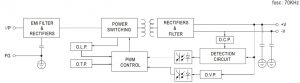
Block Diagram
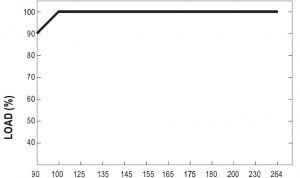
Derating Curve
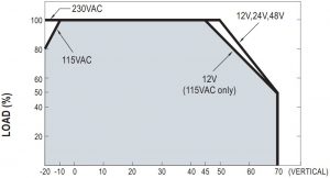 AMBIENT TEMPERATURE ( )
Static Characteristics
 INPUT VOLTAGE (V) 60Hz
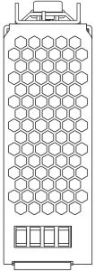
Mechanical Specification
- Case No.992D Unit:mm
 Top View
 - Side View
- Front View
- Side View
- Bottom ViewTerminal Pin No. Assignment (TB1)
Pin No.
Assignment
1
FG
2
AC/N or DC –
3
AC/L or DC +
Terminal Pin No. Assignment (TB2)
Part No.
Assignment
1
DC OUTPUT -V
2
DC OUTPUT+V
 Top View
 Side View
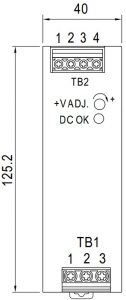 Front View
 Side View
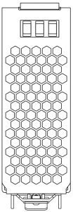 Bottom ViewTerminal Pin No. Assignment (TB1)
Installation Instruction
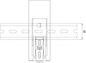 Back ViewADMISSIBLE DIN-RAIL:TS35/7.5 OR TS35/15.(For reference only. Not included with unit.)
This series fits DIN rail TS35/7.5 or TS35/15.For installation details, please refer to the Instruction manual.
Installation Manual
Please refer to : http://www.meanwell.com/manual.html
References
[xyz-ips snippet=”download-snippet”]