NANLITE NGU-NA122026 Forza 500 LED Spotlight User Manual
Technical Data
- LED Power: 500W
- Power Input: 48V Power adapter
- 2 PCS 26V/12A Sony V-mount Batteries(Not Included)
- Color Temperature: 5600K
- CRI(Ra): 98
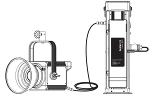
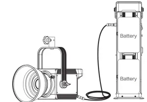
Connection Way of the Power
- Connection between light fixture and power adapter.

- Connection between light fixture and batteries.
Product Details
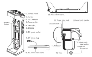
Detailed description
- Battery holder: For installing two 26V/12A Sony V-Mount batteries or power adapter.
- Control panel: For displaying various function operations and data.
- Handle: It is convenient for users to carry the host.
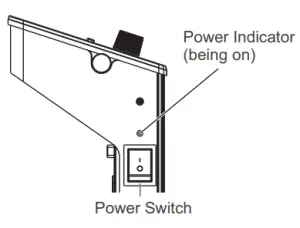
- LED indicator: For determining the status of power input. Being on, power supply is normal. Flashing or being off, power supply is abnormal or no power input.
- Power switch: For on/off the fixture.
- DMX OUT: DMX signal output interface.
- DMX IN: DMX signal input interface.
- DC power socket: DC power output interface.
- DC power plug: For connecting the DC power plug to power the lamp.
- AC power input socket: For connecting the AC power cable to supply power to the adapter.
- Host output socket: To connect the DC cable for the connection between the lamp body and the controller.
- Angle fixing knob: For adjusting and fixing the vertical illumination direction of fixture.
- Lock catch: For installing and disassembling reflector and other accessories with Bowens mount..
- Reflector: For gathering light to improve central illumination.
- Yoke: For connecting the lamp to the light stand and adjusting the angle of the light.
- Lamp body handle: Be convenient for users to lift the lamps and adjust the direction of the light.
- Lamp body input socket: For the lamp to be connected with a DC cable for the connection between the lamp body and the controller.
- Bracket fixing knob: For connecting the spot light and camera equipment , and adjusting the horizontal illumination direction of fixture.
Usage
Power Connection
- When connect the power supply, please make sure the power , voltage and frequency should be consistent with theprovided power supply.
- When use the V mount batteries, please make sure turn off the fixture and then plug in or pull out the batteries or DC cable.
NOTE:
- Make sure to use the provided power cable and power adapter.
- Make sure the plug of power supply and the cable to the socket of the fixture should be connected as following.Pin1+: connect with power supply +Pin1-: connect with power supply –Pin2+: connect with switchPin2-: connect with switch
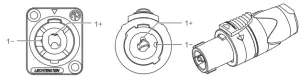 Pin1+: connect with power supply +Pin1-: connect with power supply –Pin2+: connect with switchPin2-: connect with switch
Connection with the controller
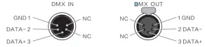
- he connection between the light fixture and control unit , light fixture and light fixture should use four core shielded cable and make sure its diameter is less than 0.3mm. XLR plug/socket and the wire should be connected as the pictures above.
- Pin1, Pin2, Pin3 for connecting DMX signals, Pin4, Pin5 is connectionless.
NOTE:
When connect with socket, make sure the internal pin not be in contact with the inner case. The fixture can match theDMX512(1990) control signal.Plug of five-core and three-core XLR plug/socket conversionThe fixture comes with the five-core XLR plug. If you use the three-core XLR plug, kindly follow below instruction.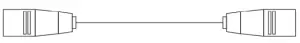
Five Pin
Pin 1:GND(SCREEN)Pin 2:Signal(-)Pin 3:Signal(+)Pin 4:N/CPin 5:N/C
Three Pin
Pin 1:GND(SCREEN)Pin 2:Signal(-)Pin 3:Signal(+)
Plug of DMX Circuit
In DMX mode, make sure the last light is the only light with cable connected to DMX output. There is a resistance about 120(OHM) between the second pin and third pin of this plug( as below photo). Make sure this plug be installed into the output of the last fixture, which can avoid noise and reflection phenomenon caused by DMX signal in the transmitting process
DMX Channel Control
Forza 500 comes with 3 control channels inlcuding” “Brightness Control”, “Special Effects Mode ” and “Flash Time Setting ”.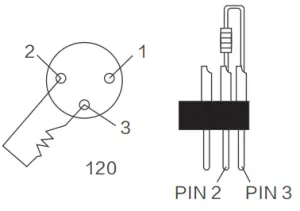
2.4G Remote Control
·Forza 500 is designed to work with 2.4G remote control or NANLITE Wi-Fi app via Wi-Fi transfer device to control the light freely.NOTE :2.4G remote control or WiFi transfer devices should be bought additionally. ( See
separate instructions for remote or Wi-Fi transfer device )
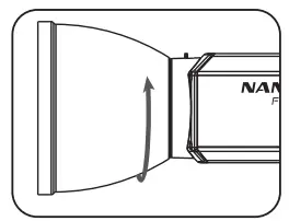
Installation Instruction of Reflector
When installing the reflector, make sure its mount points line up with the slots on the light fixture . When the mount points and slot are lined up push the reflector in place rotate reflector in the locking direction as describe on light until you hear it click into place.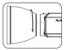
Light stand clamp
Push the button to open the clamp.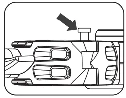
When removing the reflector, push and hold on release button until rotating the reflector and you are able to remove it from fixture.
Put this clamp on the light stand and rotate clamp in the locking direction to fix it.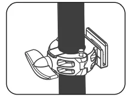
Push the release button to remove the reflector.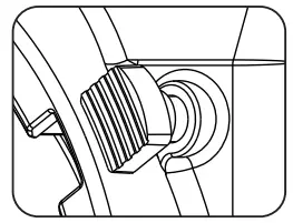
Button up the power adapter into its slot.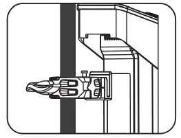
Operating Instructions
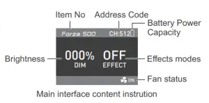
- Wiring (sketch maps as below ① First, be sure that the power switch of the control unit is in the “off ” position. Now it is safe to connect the ballast adapter or batteries and power the unit on. If the power indicator is on that means the power supply is nominal. The LCD screen will display all the relevant information for the fixture. From the remaining battery power in top right corner, to the effects mode status and percentage of power output.
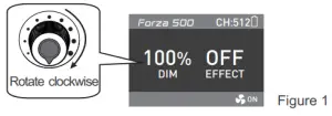
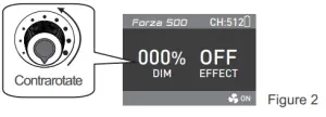
- Brightness setting: Rotate the dimmer knob, brightness can be increased when forward adjust, while reverse adjust, the brightness can be decreased. DIM shows brightness percentage on the display, and the dimming range is 0-100%. (As shown in figure 1-2)
- EFFECT Button: When pressing the “EFFECT” button, If display shows” OFF”, it is the locked status, so it cannot operate the special effect mode . If “Effect” button is pressed again, the status is now unlocked. (As shown in figure 3)in the “off” position, press the “EFFECT” button again to release the Locking state.
- Forza 500 provides 9 different light modes, turn on the fixture to enter the main interface and rotate the “Function Knob” clockwise, the order on the display is”FLASH 1(0.25 seconds)/FLASH 2(1 seconds)/FLASH 3(0.1-6 seconds)/ STORM 1(flash for 7 times continuously) /STORM 2(flash for 7 times continuously)/STROM 3(10-15 seconds in random variations)/TV/Bad Bulb. (As shown in figure 4)
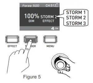
- When under STORM 1 or STORM 2 lighting mode, pressing the TRIGGER Button, it will trigger the corresponding function. (as shown in Figure 5)Some special lighting effects may be updated for the upgraded controller firmware, please learn more details about our newest function description.In FLASH 3 mode, press the “Function Knob” to set the flash time within 0.1-6 seconds.In TV mode, press the “Function Knob” to set the changing speed within 0 100.
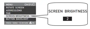
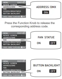
- MENU Button: Press the MENU Button, the main menu function selection will appear on the display including “Rotate Screen”, “Address/DMX”,” Fan Setting”, “Screen Setting”, “Button setting”. The “Rotate Knob” can select different items, press the “Rotate Knob” to enter the corresponding secondary menu and the “MENU button” to return. (as shown in Figure 6)
- Fan Setting: When the fan status is in the “off ” position, it does not work, and now the power output is 100W. When the fan status is in the “on ” position, now the light fixture is at full output power.
- Lock Button: Press the“Lock Button” for locking the functions. At this moment, the operation button or knob cannot change the current state. Press the “Lock Button” again to release the Locking state.
- When stop using the fixture, turn off the switch.
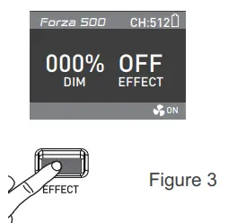 in the “off” position, press the “EFFECT” button again to release the Locking state.
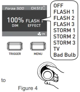
 Some special lighting effects may be updated for the upgraded controller firmware, please learn more details about our newest function description.In FLASH 3 mode, press the “Function Knob” to set the flash time within 0.1-6 seconds.In TV mode, press the “Function Knob” to set the changing speed within 0 100.
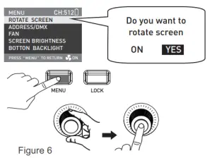
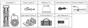
What’s in the box
Please kindly check.
Notice
- When the spot is on don’t look direct at the emitter.
- Don’t place objects on the light emitter or allow liquid to flow inside the fixture or the emitter.
- Don’t place fixture near flammable substances like alcohol or gasoline.
- When cleaning the fixture, please wipe off debris or dirt using a clothes and only dampen with water or a light cleanser.
- The Forza 500 should be safely operated where it won’t be at risk of getting wet or under extreme temperatures. Please make sure the ventilation fan is not blocked or obstructed.
- Do not repair the Forza 500 by yourself. Professionals, please adhere to the user manual while troubleshooting.
Safety Precautions
- Please open the package to check if it is damaged due to transportation after receiving the light. In case of damage caused by transportation, please do not use this light and contact the dealer or manufacturer as soon as possible.
- Do not use a power cord with damaged insulation. Do not unplug hard or drag the power cord directly.
- Make sure that the power supply voltage used matches the voltage specified by the light before installation.
- When not using or cleaning the light, please turn it off.
- Keep the light safely stored and away from children.
Genaral Fault Detection and Diagnosis
| Fault Detection | Diagnosis |
| The light won’t boot up properly! | 1. Please check the LED indicator. If flashing or not on at all, please check whether the connection between power adapter, power cable and outlet connection is properly
connected or loose. 2. Please check whether the voltage value is within specified parameters. 3. If using batteries, check if batteries are rated at or above 12A 26V. |
| The fixture produces light,
but controls are not working. |
1. Please check to see if address code corresponds with remote or app.
2. Please check and see if XLR signal line is connected properly or if the line or port is damaged. |
| LCD display is on but no light output. | 1. COB or main board is damaged.2. Connecting lines of LED COB fall off. |
| The inside fan will not work. | 1. Please check if the fan is in the “off’ position.
2. When the LCD screen display “Fan Error”, please change the fan with the supplier or manufacturer. |
The instruction was written according to the strict prodution test of our company, if there are 13 any changes related to the design of the product later, we will not keep you updated for that.
 report this ad
PHONE: +86-754-85751187Email: [email protected]+86-754-85300887Zhanglin,324,Dongli Chenghai Shantou Guangdong China
References
[xyz-ips snippet=”download-snippet”]