V1.1-M 13Apri2020
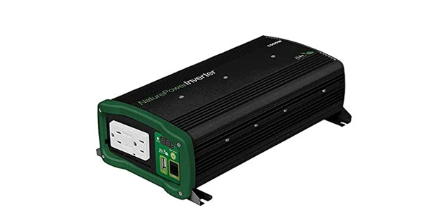
![]() Nature Power 1000 Watt Power InverterUser Manual
Nature Power 1000 Watt Power InverterUser Manual
![]() WARNING Read carefully and understand all ASSEMBLY AND OPERATION INSTRUCTIONS before operating. Failure to follow the safety rules and other basic safety, precautions may result in serious personal injury.
WARNING Read carefully and understand all ASSEMBLY AND OPERATION INSTRUCTIONS before operating. Failure to follow the safety rules and other basic safety, precautions may result in serious personal injury.
Item #37001SAVE THESE INSTRUCTIONS
Tan you for choosing a Nature Poer Product.This product is designed for certain applications only. The distributor cannot be responsible for issues arising from modification. We strongly recommend this product not be modified and/or used for any application other than that for which it was designed. If you have a question relative to a particular application, o not use the product until you have first contacted the distributor to determine if it can or should be performed on the product.For a technical question please call 1800-588-0590
PART LIST
| Reference | Part Description | Quantity |
| 1 | 100 W Inverter | 1 |
| 2 | Battery connecting cable red and black | 1 |
| 3 | Ground wire | 1 |
| 4 | User Manual | 1 |
![]() WARNINGThis product can expose you to chemicals, including Di (2-Ethylhexyl) phthalate (DEHP) which is known to the State of California to cause cancer, birth defects or other reproductive harm. For more information, go to www.p65warnings.ca.gov
WARNINGThis product can expose you to chemicals, including Di (2-Ethylhexyl) phthalate (DEHP) which is known to the State of California to cause cancer, birth defects or other reproductive harm. For more information, go to www.p65warnings.ca.gov
IMPORTANT SAFETY INSTRUCTIONS
SAVE THESE INSTRUCTIONS.
- SAVE THESE INSTRUCTIONS. This manual contains important safety and operating instructions for power inverter 1000W. This manual will show you how to use your inverter safely and effectively. Please read, understand and follow these instructions and precautions carefully.
- Keep out of reach of children.
- Do not expose inverter to rain or snow.
- Use of an attachment not recommended or sold by the unit manufacturer may result in a risk of fire, electric shock, or injury to persons.
- Do not disassemble the unit; take it to a qualified serviceman when service or repair is required. Incorrect reassembly may result in a risk of electric shock or fire.
- To reduce risk of electric shock, unplug unit from outlet before attempting any maintenance or cleaning. Turning off controls will not reduce this risk.
- For the most effective use, place the power inverter on a flat surface.
- Do not place the inverter on or near heating vents, radiators or other sources of heat or flammable meterials.
- Do not place the inverter in direct sunlight. The ideal air temperature for operation is between 50° and 80°F.
- Only connect the power inverter to a 12V battery or power supply. Do not attempt to connect the inverter to any other power source, including an AC power source. Connecting to a 6V or 16V battery will cause damage to the inverter.
- Do not use the inverter with a product that draws a higher wattage than the inverter can provide, as this may cause damage to the inverter and product.
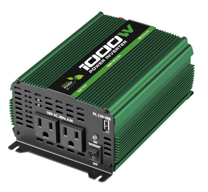
FEATURES
- ON/OFF rocker switch
- LED indicatorGreen indicates Power ON Red indicates Overload/Interruption in power
- 12 Volt power cord
- 120V standard AC outlets (2)
- USB port(s) 5V, 2.0A
- High-speed cooling fanTo keep the inverter cool, the fan turn on depend on the temperature in the inverter. The fans do not run when the inverter is turned off.
- Positive Battery Cable Terminal (Red)
- Negative Battery Cable Terminal (Black)
CONNECTING INVERTER CABLES
The inverter and power source must be in the OFF mode.IMPORTANT: Make sure to connect your inverter only to a 12-volt power supply. To avoid electrical shock, it is necessary to ground the inverter as well as the device powering it. The inverter should be grounded, using a 15 AWG copper wire (included).NOTE: Do not turn on the inverter or the power source until the inverter and the power source are grounded.
TO GROUND THE INVERTER
- Turn off and disconnect the inverter.
- Locate the chassis ground screw on the back of the inverter.
- Remove the outer nut and loosen the first locking washer.
- Attach the grounding wire’s ring connector to the ground terminal of the inverter.
- Tighten the locking washer securely. Then, replace the other nut and tighten it securely.
- Attach the other end of the wire to a properly grounded location:Vehicle: Connect to the chassis, unpainted frame part, or engine block of the vehicle.Fixed location: Connect to a ground rod or other appropriately rated ground.
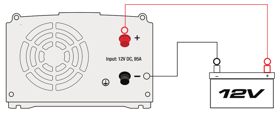
CONNECTING INVERTER CABLES TO THE INVERTER
- Locate the Positive and Negative terminals on the inverter.
- From the POSITIVE (RED) and the NEGATIVE (BLACK) terminals, remove the nut, split lock and flat washer.
- Place the POSITIVE (RED) ring connector onto the POSITIVE (RED) inverter terminal. Place the NEGATIVE (BLACK) ring connector onto the NEGATIVE (BLACK) inverter terminal.
- Place a flat washer and split lock on top of each ring connector. Put a nut over these and tighten.
 NOTE: Please use the cables we provided, DON’T use battery clamps.
 NOTE: Please use the cables we provided, DON’T use battery clamps.
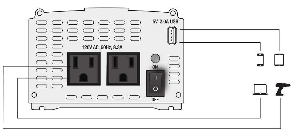
OPERATING INSTRUCTIONS
- Connect the inverter (see Connecting Inverter Cables section.
- Switch the inverter’s ON/OFF switch to the ON (I) position.
- The GREEN LED indicator will light, indicating the inverter is receiving power.
- Switch the inverter’s ON/OFF switch to the OFF (O) position. (Then the GREEN LED may flash briefly and/or the internal speaker may make a brief “beep”. This is normal.)
- Make sure the device to be operated is turned OFF.
- Plug the device into the inverter’s AC outlet.
- Switch the inverter’s ON/OFF switch to the ON (I) position.
- Turn the device on.
- To disconnect, reverse the above procedure.NOTE: If more than one device is to be powered, start one device at a time, to avoid a power surge and overloading the inverter. The surge load of each device should not exceed the inverter’s Continuous Operation wattage rate.IMPORTANT: Using the inverter with some rechargeable devices may damage the inverter and/or device. If you are using the inverter to operate a rechargeable device, monitor the temperature of the inverter for about 10 minutes. If the inverter becomes abnormally hot, disconnect it from the device immediately; do not use the device with the inverter.
POWER SOURCE
Your average automobile battery at full charge will provide an ample power supply to the inverter when the engine is on. Keep the car running at all times when using the inverter. The actual length of time the inverter will function depends on the age and condition of the battery and the power demand being placed by the device being operated with the inverter.When possible, recharge your batteries when they are not more than 50% discharged. This gives the batteries a much longer life cycle than recharging when they are more deeply discharged.
The power inverter has a battery low voltage shutdown at 10V±0.5V DC. With moderate to heavy loads, this will protect against over-discharging the battery. If the inverter is running only light loads it is advisable to recharge before the inverter low voltage shutdown point is reached.IMPORTANT: The inverter draws low amperage from the battery with the main ON/OFF switch turned on and no load connected. To prevent battery discharge, turn the inverter off when you are not using it.
LED INDICATOR AND SHUTDOWN PROTECTION
The Green LED lights automatically when the inverter is plugged into a 12 volt DC power source and is turned on. The Red LED lights, the alarm sounds and the inverter automatically turn itself off under the following conditions:
- When the power input from the vehicle’s battery drops to approximately 10.5 volts, the low voltage alarm will sound. When the voltage goes down below 10 VDC, the inverter shuts off. Recharge or replace the battery.
- When the power input from the vehicle’s battery exceeds 16 volts, high voltage protection occurs.
- The continuous load demand from the equipment or device being operated exceeds the continuous load rating of the inverter. Use a higher capacity inverter or lower-rated device.
- The thermal resistor exceeds 80° C (176° F.) Allow the inverter to cool. Do not block the cooling slots airflow over and through the inverter Reduce the load on the inverter to the continuous rated output.
RESET: To reset after shutdown occurs, switch the inverter’s ON/OFF switch to the OFF (O) position. Check the source of the problem and correct. Switch the inverter’s ON/OFF switch to the ON (I) position.
IF THE INVERTER’S FUSE BLOWS
Your power inverter is fitted with fuses, which should not have to be replaced under normal operating conditions. A blown fuse is usually caused by reverse polarity or a short circuit within the device or equipment being operated. If a fuse does blow, take the inverter to a qualified technician for repair.
MAINTENANCE AND STORAGE INSTRUCTIONS
- Before each use, ensure that all of the inverter’s components are in place and in good working condition.
- After use and before performing maintenance, unplug and disconnect the inverter.
- Use a clean, dry cloth to wipe the external surfaces of the inverter’s case.
- Servicing does not require opening the unit, as there are no user-serviceable parts. All servicing should be performed
- Store inside, in a cool, dry place, out of the reach of children.
- Recycle or properly dispose of internal electrical components.
TROUBLESHOOTING
|
PROBLEM |
POSSIBLE CAUSE |
REASON/SOLUTION |
| Low or no output voltage. | POSSIBLE CAUSE Poor contact at terminals OVP/OLP. Using incorrect type of voltmeter to test output voltage. | Disconnect and reconnect the 12V connections. Use a true RMS reading meter. |
| Red LED is lit. |
The battery voltage is below 10 volts. The equipment being operated is drawing too much power. The inverter is too hot (thermal shutdown). |
Recharge or replace the battery. Use a higher capacity inverter or decrease the load or device on the inverter Allow inverter to cool. Check for adequate ventilation. Reduce the load on the inverter to the rated continuous power output. |
| Alarm sounds continuously. | Input voltage is below 10 volts. Poor or weak battery connection. |
Recharge or replace the battery. Check for poor connection to battery. Make sure connection points are clean. |
|
Device does not operate properly when first connected to the inverter. |
The inverter may not have the required capacity to operate the device. |
Turn the inverter switch OFF and ON, to reset the inverter. |
SPECIFICATIONSNominal input voltage ……………………………………………………………………….12.8-13.2 VDCNominal output voltage ……………………………………………………………………..115±10% VACOutput frequency ………………………………………………………………………………………..60±3 HzOperating input voltage……………………………………………………………………………….10.0-15.0VDC Continuous output power ………………………………………………………… Up to 1000 WSurge output power………………………………………………………………………………………. 2000 WWaveform………………………………………………………………………………….. Modified sine waveEfficiency (typical) …………………………………………………………………………………………… 86%Typical No Load Current (at nominal input voltage) ………………………………………….0.4ADC Input overvoltage shutdown ……………………………………………………………15.5±0.5VDC Input undervoltage alarm ………………………………………………………………..10.5±0.5VDC Input low voltage shutdown……………………………………………………………..10.0±0.5VDC Output power overload shutdown level………………………………………1300±300 WInput fuse …………………………………………………………………………………………………….3×40 AAC receptacles……………………………………………………………………..Two, NEMA 5-15 USAUSB port ……………………………………………………………………………………………. One, 5V 2ABattery cables …………………………………………………………………………….. 7AWG, 2×39.3 inGround wire ……………………………………………………………………………….15AWG, 1×39.3 in
LIMITED WARRANTY
Nature Power warrants our products to the original purchaser that this product is free from defects in materials and workmanship for the period of one year from date of purchase. In the case of product defect, contact Nature Power customer service to receive troubleshooting. If defective part or unit should be returned, a Return Authorization Number must be issued by Nature Power and the defective part or unit should be returned to the authorized location at the purchasers’ expense. A dated proof of purchase is required to receive warranty service. Once received at authorized location and defect proves to be the result of defective material and workmanship, the defective part or unit will be replaced at warrantors’ option and returned to the original purchaser at warrantors’ expense. No refunds will be granted by the warrantor, In the event of buyer’s remorse Please contact your point of purchase and adhere to their return policy.
![]() Please contact Nature Power Products to acquiremore information: 1-800-588-0590[email protected]www.naturepowerproducts.comMade in Taiwan
Please contact Nature Power Products to acquiremore information: 1-800-588-0590[email protected]www.naturepowerproducts.comMade in Taiwan
References
[xyz-ips snippet=”download-snippet”]