NAVAC Flammable Refrigerants User Manual
GENERAL SAFETY
Use information
- In order to prolong the life cycle of the recovery unit, please read the manual carefully before using to fully understand the safety, specification as well as operating procedure of the recovery unit.
- Please check the product received is same as you ordered . Please check the product if there is any damage during transportation.Contact with local distributor if the above problem is found.
- Please read the manual carefully and use the unit according to the product operating procedures.
Safety indication
warning
This mark indicates procedures that must be strictly observed to prevent hazards to people
 This mark indicates procedures must be strictly observed to prevent damage or destruction of the unit.
Matters needing attention
Warning
For recovering only HVAC/R refrigerants from sealed HVAC/R systems. Warranty VOIDED if used for any other purposes.Only a qualified technician should operate this recovery unit.Before starting the equipment, make sure that it is well grounded.If using electrical extension cord, the cord must be in good condition and properlyOnly a qualified electrician can do the wire connection according to the technical standard and circuit diagram. connected and grounded.The power must be cut off and no display in LCD before inspecting or repairing.If the original power supply cord is damaged, an OEM replacement may be ordered through your NAVAC distributor.Please take power supply and the capacity of your ammeter and electrical wire.
GENERAL SAFETY
Only authorized refillable refrigerant tanks can be used. The setting of the pressure limiting device shall not be lower than 45 bar(653psi). Do not overfill the recovery tank, maximum at 80% capacity to make sure that there is enough space for liquid expansion. Overfilling of the tank may cause a violent explosion. Always wear safety goggles and protective gloves while working with refrigerants to protect your skin and eye from hurting by refrigerant gases or liquid. Do not use this equipment near flammable liquid or gasoline. A digital scale is needed to prevent overfilling. Be sure that the place where you are working is thoroughly ventilated.

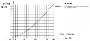
Be sure the unit is working under the right power supply. When using an extension cord it should be minimum 14 AWG and no longer than 25 feet, otherwise it may cause the voltage drop and damage the compressor. The input pressure of the unit should not exceed 26bar(377.0psi) . The unit need to be laid in horizontally, otherwise it will lead to unexpected vibration, noise or even abrasion. Do not expose the equipment to sun or rain. The ventilation opening of the unit must not be blocked. If the overload protector pops, reposition it after 5 minutes. When doing self purging operation, the knob must be turned slowly to “PURGE” to ensure the inlet pressure is less than 5 bar(72.5 psi). If fluid hammer happens in the recovery, please turn the knob slowly to “SLOW” position and do not let reading pressure drop to zero. When you select fast model to start work, please monitor output pressure, if the output pressure increase fast to 27bar(391 .6 psi),please turn to slow mode slowly and monitor the outlet pressure not exceeding 35bar(507.6 psi). The equipment is intended for serving air-conditioning and refrigeration systems containing less than 200 lbs of high-pressure refrigerant. The tank and hose used must with the local regulations.
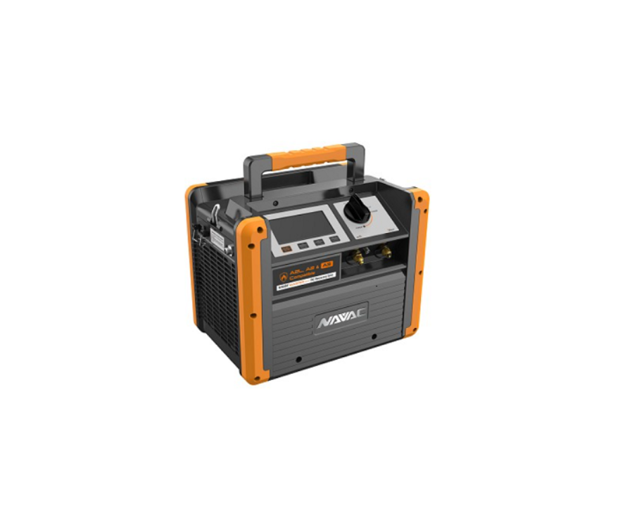
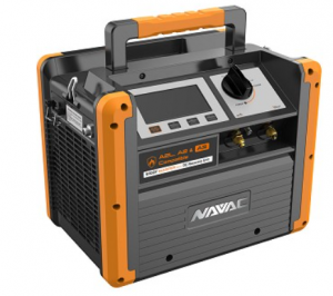
SPECIFICATION
NRDDF
| Refrigerants | Category III: R12, R134a, R401C, R500, R1234YF, R600aCategory IV: R22, R401A, R401B, R402B, R407C, R407D, R408A,R409A, R411A, R411B, R412A, R502, R509, R290Category V: R32, R402A, R404A, R407A, R407B, R410A, R507 |
| Power | 115V, 60Hz |
| Motor Speed | 3000 RPM |
| Maximal Current Draw | 12A |
| Compressor | Oil-less, Air-cooled, Piston |
| High Pressure Protector | 38.5bar/3850kpa(558psi) |
| Operating Temperature | 32~104°F |
| Dimensions | 14.5×9.9×11 .7 inch |
| Net Weight | 25 lbs |
NRDDF
| Rerfigerants | R-22a | R-134a | R-410a |
| High Temp Vapor | 0.62 lbs/min | N/A | N/A |
| Direct Vapor | 0.55 lbs/min | 0.37 lbs/min | 0.49 lbs/min |
| Direct Liquid | 6.88 lbs/min | 5.34 lbs/min | 7.98 lbs/min |
INTRODUCTION OF OPERATION PANEL
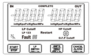
Start/Stop: Starts and Stops recovery unit LP Switch: Hold for 3 seconds to switch between LP1 , LP2, LP3 Units/Zero: Press to change units to lnHg, Kpa, Psi, Kg/f, Bar, Mpa. Hold for 3 seconds to zero out readings Cancel Alarm: Hold for 3 Seconds to mute recovery unit LP1 : (Auto shutoff with manual restart)If the inlet pressure is lower than -20inHg for 20 seconds, the unit will shut down. “LP Cutoff’ will be displayed. When LP 2: 0 inHg you must press START to restart the recovery unit LP2: (Auto Shutoff with automatic restart) If the inlet pressure is lower than -20 inHg for 20 seconds the unit will shutdown “LP Cutoff’ is displayed. When LP 2: 0 inHg the unit will restart automatically LP3: (Continuous Run)The recovery unit will run continuously, no matter what the level the input pressure is (LP)
O.F.P Cutoff: Will Light up when the recovery cylinder is 80% filled, or if the OFP cable is shorted. The machine will stop running LP Cutoff: Will light up when low pressure switch is activated for more than 20 seconds below -20 inHg HP Cutoff: Will Light up when high pressure switch is activated above 560 Psi
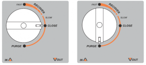
Close: Inlet valve is closed Recover: Input valve is partially opened Fast: Input valve is fully opened SLOW VoUT Purge: Input closed, and output is opened to allow the unit to remove most of the refrigerant inside the recovery machine
Fault: Error Codes
- E 1: The pressure sensor is disconnected
- Fault 2: Input voltage is too low
- Fault 3: High input voltage
- Fault 4: Overcurrent protection
- Fault 5: Temperature sensor open
- Fault 6: Temperature sensor short circuit
- Fault 7: Temperature protector open
![]() Mute: Audible alerts and beeps are turned off
Mute: Audible alerts and beeps are turned off![]() Fan: This icon rotates while the machine is running. When the machine stops, the icon stops rotatingRestart: It will flash after an error has occurred and settled. Pressing START will resume activity.
Fan: This icon rotates while the machine is running. When the machine stops, the icon stops rotatingRestart: It will flash after an error has occurred and settled. Pressing START will resume activity.
PARTS DIAGRAM
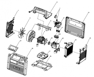
NO. Parts name
- Left Side Plate 12 Compressor 12 Compressor
- Fan 13 Condenser 13 Condenser
- Wind Guide Cover 14 Rear Plate 14 Rear Plate
- Motor 15 Right Side Plate 15 Right Side Plate
- Support Assy 16 Base 12 Base
- Top Plate 17 Motor Control 13 Motor Control
- Knob 18 Front Side Plate 14 Front Side Plate
- Control Assy 19 15 Digital Control Board
- ValveAssy
- Cylinder
- Coupling
WIRING DIAGRAM
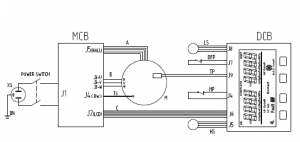
| Graphics Code | ITEM |
| HS | High pressure sensor |
| M | Motor |
| MCB | Motor control board |
| XS | Socket |
| DCB | Digital gauge control board |
| LS | Low pressure sensor |
| OFP | Over filling protector |
| TP | Temperature protector |
| HP | High pressure switch |
| TS | Temperature sensor |
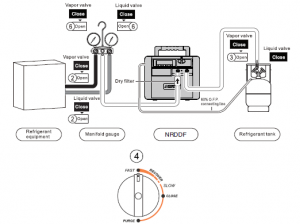
OPERATING INSTRUCTION
1 ). Refrigerant hoses exhaust
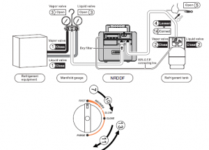
Ready for operation
Connect the hoses correctly and firmly. ( Please refer to the connection diagram)
- Confirm the vapor valve and liquid valve of AC system are in close position.
- Confirm the vapor valve and liquid valve of recovery tank are in close position.
- Open the vapor and liquid valves of manifold gauge.
- Loosen the connecting pipes of refrigerant tank.
- Open the check valve of pipes.
Start operation
- Plug in the machine, tum on the power, and the LCD shows pressures.
- Press the ” START” button to start machine.
- Turn the knob to recover,
- Observe the reading of the low pressure gauge when it reaches to -20inHg, after 20 seconds, LP cutoff opens and the machine shuts off.
- Turn the knob to “Close”, LP cutoff blinks, press the power button and start machine.
- Turn the knob slowly to “Purge” and start self purging.
- Observe the reading of the low pressure gauge when it reaches to -20inHg for the second time, after 20 seconds,LP cutoff turns on and the machine stops work
Finish operation
- .Turn the knob to “Close” and stop self purging.
- the refrigerant hose to the tank.
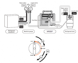
OPERATING INSTRUCTION
2). Recovery mode
Ready for operation
Connect the hoses correctly and firmly. ( Please refer to the connection diagram) Make sure all valves are closed.
- Switch off the power of refrigerant equipment.
- 0pen the vapor and liquid valves of refrigerant equipment.
- 0pen the vapor valve of the refrigerant tank.
Start operation
- Press the “START” button to start machine.
- Turn the knob to “Recover”.
- a. If recover liquid refrigerant, please open the liquid @ valve of the manifold gauge.b. If recover vapor refrigerant, please open the vapor valve of the manifold gauge.
- The recovery mode will be finished when machine runs to certain vacuum or automatic close of low pressure protection.Do not turn off the power after recovery finished and directly run self purging mode
Notice
- f fluid hammer happens in the recovery, please turn the knob to “Slow” position slowly, then the reading of low pressure gauge drops until fluid hammer stops; but do not let reading pressure drop to zero, otherwise inlet port is not pumping once at zero pressure.
- If it is difficult to start, turn to “CLOSE” when liquid, turn to “PURGE” when vapor, then press “START” to restart the machine, and turn to the required position.
OPERATING INSTRUCTION
3). Self-purge mode
Notice
The unit must be purged after each use; liquid refrigerant remained may expand and damagethe components and pollute the environment.
Start operation
- The machine stops automatically after recovery finished LP cutoff
- Turn the knob to “Close” and the LP cutoff blinks , press” START” button to start the machine.
- Turn the knob to “Purge” and start self purging.
- The self purging mode will be finished when machine runs to certain vacuumFinish operation
- Turn the knob to “Close”.
- Turn off the power switch. Disconnect power cord.
- Close the check valve which connected to exhaust.
- Close the 10por valve of the tank.
- Disconnect all hoses.
OPERATING INSTRUCTION
4). Liquid push/pull mode
Notice
An electric scale is needed to monitor the process to prevent overfilling.
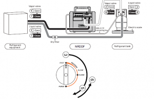
Ready for operationConnect the hoses correctly and firmly. ( Please refer to the connection diagram) Make sure all valves are closed.
Start operation
- 0pen the vapor valve, liquid valve of the HVAC system.
- 0pen the vapor valve, liquid valve of the tank.
- Press “START” button to start machine, then it starts liquid push/pull mode.
- Turn the knob to “Recover”.If the reading on the scale keeps the same or changes slowly, it means liquid in HVAC system has been recovered and vapor recovery mode can be underway.
- Turn the knob slowly to “Purge” and start self purging mode for the liquid.
- Turn the knob to “Close”.
- .Close the vapor valve, liquid valve of the HVAC system.
- Close the vapor valve, liquid valve of the tank.
- Reconnect the hoses and start recovery mode for the vapor.
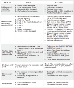
TROUBLE SHOOTING
Read More About This Manual & Download PDF:
[xyz-ips snippet=”download-snippet”]