
NAVAC NRDDF Recovery Unit For Flammable Refrigerants User Manual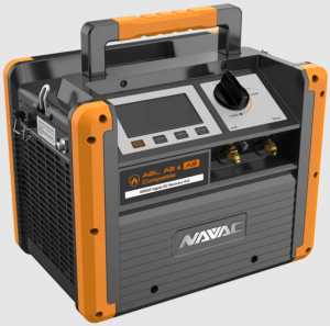
CERTIFICATIONS
Design standard:UL 121201: Ninth EditionCSA-C22.2 No.213-17UL 1963: Fourth EditionCSA-C22.2 No.120-13IEC: 60079-0, 60079-7
Marking:Class I, Division 2, Group D T4

![]() WEEE (Do not dispose through typical waste streams)
WEEE (Do not dispose through typical waste streams)
IN ACCORDANCE WITH SECTION 608 OF THE CLEAN AIR ACT:THIS EQUIPMENT HAS BEEN CERTIFIED BY UNDERWRITERSLABORATORIES INC. TO MEET EAP’S MINIMUM REQUIREMENTFOR RECOVERY EQUIPMENT INTENDED FOR USE WITH CATEGORY III, IV, AND V REFRIGERANTS OUTLINED IN AHRI-740-98, TABLE 4.
GENERAL SAFETY
Use information
- In order to prolong the life cycle of the recovery unit. please read the manual carefully before using to fully understand the safety. specification as well as operating procedure of the recovery unit.
- Please check the product received is same as you ordered. Please check the product if there is any damage during transportation. Contact with local distributor if the above problem is found.
- Please read the manual carefully and use the unit according to the product operating procedures.
Safety indication
![]() WarningThis mark indicates procedures that must be strictly observed to prevent hazards to people.
WarningThis mark indicates procedures that must be strictly observed to prevent hazards to people.
![]() NoticeThis mark indicates procedures must be strictly observed to prevent damage or destruction of the unit.
NoticeThis mark indicates procedures must be strictly observed to prevent damage or destruction of the unit.
Matters needing attention
![]() Warning
Warning
- For reconvening only HVACIR refngerants from sealed HVACCR systems. Warranty VOIDED if used for any other purposes.
- Only a qualified technician should operate this recovery unit.
- Before starting the equipment, make sure that it is well grounded.
- If using electrical extension cord. the cord must be in good condition and properly connected and grounded.
- Only a qualified electrician can do the wire connection according to the technical standard and circuit diagram.
- The power must be cut off and no display in LCD before inspecting or repairing.
- If the original power supply cord is damaged. an OEM replacement may be ordered through your NAVAC distributor.
- Please check the capacity of your power supply, ammeter, electrical wires and circuit before use.
- Only authorized refillable refrigerant tanks can be used. The setting of the pressure limiting device shall not be lower than 45 bar(653psi). Do not overfill the recovery lank, maximum at 80% capacity to make sure that there is enough space for liquid expansion. Overfilling of the tank may cause a violent explosion.
- Always wear safety goggles and protective gloves while working with refrigerants to protect your skin and eye from hurting by refrigerant gases or liquid.
- Do not use this equipment near flammable liquid or gasoline.
- A digital scale is needed to prevent overfilling.
- Be sure that the place where you are working is thoroughly ventilated.
 Before connecting, be sure to turn on the refrigerator to check:
- If the Ian is working properly (if there’s air blowing out from the condenser side).
- Connect the check valve to the outlet port and close the check valve. Keep the inlet port open to atmosphere. Turn the knob to the “FAST’ position and start the machine. The pressure on the outlet side should rise to 560Psi (38.6bar) within 65secs. After that. the high pressure switch protection switch is on. and the machine will automatically shut down.
![]() Notice
Notice
- Be sure the unit is working under the right power supply.
- When using an extension cord it should be minimum 14 AWG and no longer than 25 feet, otherwise it may cause the voltage drop and damage the compressor.
- The input pressure of the unit should not exceed 26bart.377.0psit
- The unit need to be laid in horizontally, otherwise it will lead to unexpected vibration, noise or even abrasion.
- Do not expose the equipment to sun or rain.
- The ventilation opening of the unit must not be blocked.
- If the overload protector pops. reposition it after 5 minutes.
- When doing self purging operation, the knob must be turned slowly to ‘PURGE” to ensure the inlet pressure is less than 5 bar(72.5 psi).
- If fluid hammer happens in the recovery. please turn the knob slowly to ‘SLOW ” position and Do not let reading pressure drop to zero.
OPERATION MANUAL
- Do not mix different refrigerants together in one tank, otherwise they could not be separated or used.
- Before recovering the refrigerant, the tank should achieve the vacuum level: -29.6inHg , for purge non-condensable gases. Each tank was full of nitrogen when it was manufactured in the factory, thus the nitrogen should be evacuated before first use.
- The knob should be in the ‘Close” Position before operation. All the valves must be closed, the input and output fittings should be covered with protective caps when the unit is not in operation. The air/ moisture is harmful to the recovery result and will shorten the life span of the unit.
- A filter drier should always be used and should be replaced regularly. And each type of refrigerant must have its own filter. For the sake of ensuring the normal operation of the unit, please use highquality filter drier specified by our company. A high quality filter drier will help protect machine .
- Special-caution is needed when recovering from system, and two dry filters are needed.
- The unit has an Internal High Pressure protector. If the pressure inside the system is above rated shut-off pressure (see specification) . compressor will automatically shut off and the HP cutoff shows. To restart the compressor, please lower the internal pressure (Output gauge indicates lower than 35 bar/507.6 PSI), after the HP cutoff blinks, then Press the “START” button to restart the compressor. When high pressure protection initiates, please determine the cause and deal with it before restarting the unit. O.)
- The input valve of the refrigerant tank is closed—opening the valve will help solve the problem.
- The connecting hose between the recovery unit and refrigerant tank is plugged —close all the valves and replace the connecting hose.
- The temperature of the refrigerant tank is too high, causing high pressure— cool the tank down.
Specification
| NRDDF | |||
| Refrigerants | Category III: R12, R13a, R401C, R500, R1234YF, R600aCategory IV:R22, R401A, R401B, R402B, R407C, R407D, R408A, R409A, R411A, R411B, R412A, R502, R509, R290Category V: R32, R402A, R404A, R407A, R407B, R410A, R507 | ||
| Power | 115V, 60Hz | ||
| Motor | Brushless Motor, 1 HP | ||
| Motor Speed | 3000 RPM | ||
| Maximal Current Draw | 12A | ||
| Compressor | Oil-less, Air-cooled, Piston | ||
| High Pressure Protector | 38.5bar/3850kpa(558psi) | ||
| Operating Temperature | 32~104°F | ||
| Dimensions | 14.5×9.9×11.7 inch | ||
| Net Weight | 25 lbs | ||
| Refrigerants | R-22a | R-134a | R-410a |
| High Temp Vapor | 0.62 lbs/min | N/A | N/A |
| Direct Vapor | 0.55 lbs/min | 0.37 lbs/min | 0.49 lbs/min |
| Direct Liquid | 6.88 lbs/min | 5.34 lbs/min | 7.98 lbs/min |
| Push/pull Liquid | 14.2 lbs/min | 11.0 lbs/min | 15.1 lbs/min |
INTRODUCTION OF OPERATION PANEL
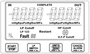
- Start/Stop: Starts and Stops recovery unit.
- LP Switch: Hold for 3 seconds to switch between L131. LP2. Lp3.
- Units/Zero: Press to change units to In Hg. Kos, Psi. KO. Bar, Mpa. Hold for 3 seconds to zero out readings.
- Cancel Alarm: Hold for 3 seconds to mute recovery unit.
- LP1: (Auto shutoff with manual restart)If the inlet pressure is lower than -20inHg for 29 seconds, the unit will shut down.‘LP Cutoff- will be displayed.When LP 2 0 inHg you must press START to restart the recovery unit •
- LP2: (Auto shutoff with automatic restart)if the inlet pressure is lower than -20inHg for 20 seconds. the and will shut down.“LP CutolF” is displayed.When LP 2 0 inHg the unit volt restart automatically.
- LP3: (Continuous Run)The recovery unit will run continuously, no matter what the level the input pressure Ls (LP)
- O.F.P Cutoff: Will light up when the recovery cylinder is 80% filed. or if the OFP cable is opened. The machine will stop running.
- LP Cutoff: will light up when low pressure switch is activated for more than 20 seconds below -20 inHg.
- HP Cutoff: Will light up when high pressure switch is activated above 560 Psi.Restart: It will flash after an error has occurred and settled. Pressing “START” will resume activityFault: Error Codes
- E1: The pressure sensor is disconnected
- Fault 2: Input voltage is too low
- Fault 3: High input voltage
- Fault 4: Overcurrent protection
- Fault 7: Temperature protector open
- Fault 8: Motor stalling
- Mute: Audible alerts and beeps are turned off.
- Fan: This icon rotates while the machine is running. When the machine stops, the icon stops rotating.
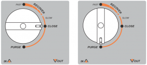
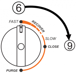
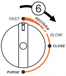
Close: Inlet valve is closedRecover: Input valve is partially openedFast: Input valve is fully openedPurge: Input closed, and output is opened to allow the unit to remove most of the refrigerant inside the recovery machine.
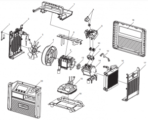
Parts Diagram
| Parts name | |
| 1 | O.F.P Adaptor Assy |
| 2 | Left side Plate |
| 3 | Fan |
| 4 | Wind Guide Cover |
| 5 | Motor |
| 6 | Support Assy |
| 7 | Top Plate |
| 8 | Knob |
| 9 | Control Assy |
| 10 | Valve Assy |
| 11 | Cylinder |
| 12 | Copper Pipe |
| 13 | Coupling |
| 14 | Compressor |
| 15 | Condenser |
| 16 | Rear Plate |
| 17 | Right Side Plate |
| 18 | Base |
| 19 | Motor Control Board (MCB) |
| 20 | Front Side Plate with Digital Manifold Gauge |
Wiring Diagram
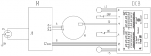
| Graphics Code | ITEM |
| HS | High pressure sensor |
| M | Motor |
| MCB | Motor control board |
| XS | Socket |
| DCB | Digital gauge control board |
| LS | Low pressure sensor |
| OFP | Over filling protector |
| TP | Temperature protector |
| HP | High pressure switch |
Operating Instruction
Refrigerant Hoses exhaust
Preparation
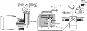
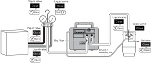
It’s required to use hoses with ball valves on this recovery machine. Connect the hose correctly and firmly (see diagram above)
- Check the refrigeration device and make sure the gasvalve and liquid valve are closed.
- Check the refrigerant tank and make sure the gas valveand liquid valve are closed.
- Open the gas valve and liquid valve of the manifoldgauge.
- Open the ball valves on the recovery machine outletand valves on the hose connected to the outlet
- Power on the recovery machine, the LCD screen willdisplay the inlet and outlet pressures.
- Turn the knob to “FAST”.Start
- Start the vacuum pump and let it run until the recovery machine’s display (low pressure) shows above -20inHg.
- Close the ball valve of the vacuum pump hose which is connected to the refrigerant tank.
- Turn the knob to “Close”.
- Connect the recovery machine outlet to the refrigerant tank with a hose
Recovery mode
Preparation
Connect the hoses correctly and firmly. (Please refer to the connection diagram)Make sure all valves are closed.
- Switch off the power of refrigerant equipment.
- Open the vapor and liquid valves of refrigerant equipment.
- Open the vapor valve of the refrigerant tank.
- Open the ball valves on the hose connected to the recovery machine outlet Start operation
- Press the “START” button to start machine.
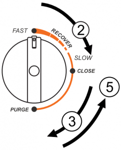
- Turn the knob to “Recover”.
- If recover liquid refrigerant, please open the liquid valve of the manifold gauge.
- If recover vapor refrigerant, please open the vapor valve of the manifold gauge.
- Recovery is completed when machine enters into
- vacuum. In Automatic shutoff this would be at -20inHg
- When recovery is completed, you can run self-purging right away without powering off
![]() Notice
Notice
- If liquid hammer happens in the recovery, please slowly turn the knob to “Slow” position, let the reading of the low-pressure gauge drops until liquid hammer stops. Do not let the reading drop to zero, otherwise the inlet port will not pump.
- lf it is difficult to start, turn to “CLOSE” when liquid, turn to “PURGE” when vapor, then press “START” to restart the machine, and turn to the required position
Self purge mode
![]() NoticeThe unit must be purged every time after use; Liquid refrigerant remained may expand and damage the components and pollute the environment.
NoticeThe unit must be purged every time after use; Liquid refrigerant remained may expand and damage the components and pollute the environment.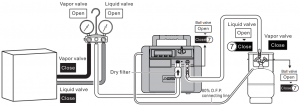
Start operation
- The machine stops automatically after recovery finished based on LP cutoff setting.
- Turn the knob to “Close”, press “START” button to start the machine.
- Turn the knob to “Purge” and start self purging.
- The self purging mode will be finished when machine automatic stops or runs to certain vacuum level.Finish operation
- Turn the knob to “Close”.
- After confirming the machine has stopped, unplug the power cord from the charger to the power socket first, then unplug the cord from the charger to the recovery machine to avoid sparks.
- Close the ball valves at both ends of the outlet hose.
- Close the vapor valve of the tank.
- Remove all the hoses and recycle them properly.
Liquid push/pull mode
![]() NoticeAn electronic scale is needed to monitor the recovery process to prevent overfilling.
NoticeAn electronic scale is needed to monitor the recovery process to prevent overfilling.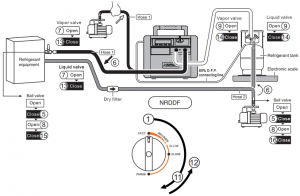
PreparationConnect the hoses correctly and firmly. (Please refer to the connection diagram)Make sure all valves are closed.
- Turn the knob to “FAST”.
- Connect hose 1 to the vacuum pump.
- Start the vacuum pump to pump the vacuum.
- Let the vacuum pump run for 20 secs, close theball valve on hose 1, turn off the vacuum pump,and remove the hose from the vacuum pump.
- Connect hose 2 and repeat step 2, 3, 4
- Connect the hoses to the gas port of the system andthe liquid port of the refrigeration tank.Start operation
- Open the vapor valve, liquid valve of the HVAC system.
- Open the ball valves on the connecting hose 1 and hose 2
- Open the vapor valve, liquid valve of the tank.
- Press “START” button to start machine, then it starts liquid push/pull mode. * If the reading on the scale keeps the same or changes slowly, it means liquid in HVAC system has been recovered and vapor recovery mode can be underway.
- Turn the knob slowly to “Purge” and start self purging mode for the liquid.
- Turn the knob to “Close”
- Close the vapor valve, liquid valve of the HVAC system.
- Close the vapor valve, liquid valve of the tank.
- Close the ball valves on the hose connecting the recovery machine outlet and the system.
- Close the ball valves on the hose connecting the refrigerant tank and the system.
- Reconnect the hoses, and start recovery mode for the vapor.Finish
Trouble Shooting
| PROBLEM | CAUSE SOLUTION | |
|
LCD does not work after power is on |
1. Power cord is damaged.
2. Inner connection is loose. 3. Connect to J6 is damaged. 4. Malfunction of circuit board.
|
1. Replace cord.
2. Check the connection. 3. Replace the connect. 4. Replace MCB or DCN circuit board. Contact NAVAC tech support |
|
Machine does not run after pressing START |
1. HP Cutoff, or OFP Cutoff works (screen shows.)
2. Fault 2 or Fault3 3. Fault 4 or Fault 8 4. Fault 7 5. Button is damaged. 6. Circuit board is damaged. |
1. Check if the connection between HP or OFP to DCB is good.
2.1 Adjust to correct voltage. 2.2 If the voltage is correct, replace the MCB 3.1 If this happens only when starting the machine: for liquid recovery, turn the knob to “CLOSE”, for gas recovery, turn the knob to “PURGE”, press “START” again to start the machine, and turn the knob to “FAST”. 3.2 Only when inlet pressure is too high or fluid hammer happens, turn the knob to “SLOW” 3.3 When error occurs at no load, power off the machine and check if the fan can be manually rotated. If yes, replace the control board. If not, send the machine back to the factory for repair. 4. Check if the connection between TP and MCB is good. If good, contact NAVAC tech support. 5/6. Replace the front side plate with digital manifold gauge. |
|
Machine stops after running a period of time |
1. Misoperation causes HP Cutoff.
2. Thermal protector is on and shows Fault 7. 3. Refrigerant is 80% in the tank, and O.F.P Cutoff shows. 4. low pressure protection switch is on.
|
1. Refer to section 6 of OPERATION MANUAL on
page 3. 2. When Fault 7 and Restart flash, press START. 3. Replace the tank. When O.F.P Cutoff and Restart flash, press START. 4. See refer to self-cleaning operation steps for self-cleaning. |
| E1 shows at LP or HP | Pressure sensor is not connected well or is open circuit. | Check if the connection between LS or HS to DCB is good. If good, replace pressure sensor. |
|
Slow recovery rate |
1. The pressure of the refrigerant tank
2. The valve is not open enough. 3. Piston ring of compressor is damaged. |
1. Cooling the tank help decrease the pressure. is too high. 2. Turn the knob towards “FAST”.3. Contact NAVAC tech support |
| Not evacuate | 1. Connection hose is loose.
2. Machine leaks. |
1. Tighten the connection hosed.
2. Contact NAVAC tech support. |
![]() AttentionIf you have the compressor repaired in any circumstances, please do a leak test before use and make sure there’s no leak.
AttentionIf you have the compressor repaired in any circumstances, please do a leak test before use and make sure there’s no leak.
How to do the leak test:
- Block the outlet port with a ball valve, keep the inlet in connection with the atmosphere;
- Turn the knob to the “FAST” and start the machine. When the outlet pressure rises to 30bar, press the “STOP”, and then turn the knob to the “PURGE”.
- Leave it alone for 30 minutes. Check the reading of the low pressure gauge. If the pressure is higher than 15bar, then it passes the test. If it is lower than 13bar, there a leak; if it is between 13bar and 15bar, leave it for another 30 minutes. If the pressure drops 5_ 2bar, then it passes the test
[xyz-ips snippet=”download-snippet”]