NAVAC NRRD Recovery Unit User Guide
Refrigerant Hoses’ Exhaust
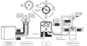
Ready for operation
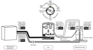
- Connect hoses correctly and tight, referring to the connection diagram.
- Open the vapor and liquid valves of manifold gauge.
- Loosen the connecting hoses of refrigerant tank.
- Open the valve to the hoses
Start operation
- Turn the switch to positon START.
- Press
 button.
 - Turn the switch to position 2 and start purging the air out of the hoses.
- While the input gauge getting to 15″ of vacuum (-1 bar) turn the switch to position 3 to start selfpurge.
- While the input gauge getting to 15”(-1 bar) again, turn the switch to position 0 to finish self-purge.
- Tighten the hoses at refrigerant tank.
Finish operation
- Press button.
Recovery Mode
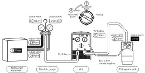
Ready for operation
- Connect hoses correctly and firmly. (Please refer to the connection diagram)
- Make sure all valves are closed.
- Turn off the power to system equipment.
- Open the vapor and liquid valves of refrigeration or air conditioning system equipment.
- Open the vapor valve of the refrigerant tank.
Start operation
- Turn the switch to the position START.
- Press button.
- Open the liquid valve for liquid recovery. Open the vapor valve for vapor recovery.
- Turn the switch slowly to positon 2 for faster recovery.
- When the recovery is finished, the unit gets to the required vacuum or automatically stops by low pressure protection
![]() Notice
Notice
- If compressor liquid slugging occurs at position 2, turn the switch to position “START”until the liquid slugging stops.
- If the recovery restarts after interruption of power or fails to start,2.1 Turn the switch to positon START, turn on the power switch, press START button for liquid recovery.2.2 Turn the switch to position 3,turn on the power switch, press START button for vapor recovery
![]() Notice
Notice
- Turning the switch to position 1 gets a stable recovery of liquid with low speed of 1.2kg/Min.
- If compressor slugging occurs at the position 1 turn the switch slowly to position START until slugging stops. Make sure the pressure is at zero, because it doesn’t work at 10.
- There is no need to turn off the power and it cando theself-purge cycleautomatically.
Self-purge Mode
![]() NoticeThe unit must be purged after each use; Liquid refrigerant remained may expand and damage the components and pollute the environment.
NoticeThe unit must be purged after each use; Liquid refrigerant remained may expand and damage the components and pollute the environment.
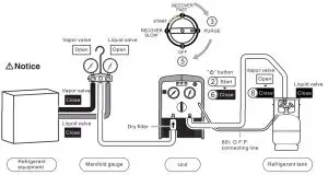
Ready for operation
- The unit stops automatically when reco very is finished.
- Press button.
- Turn the switch slowly to position 3 to start purge
- .When the self-purging cycle is finished, the unit goes into a vacuum.
Finish operation
- Turn the switch to position 0.
- Press button.
- Close the check valve to hoses
- Turn off the vapor valve of refrigerant tank.
Liquid Push/Pull Mode
![]() NoticeAn electric scale is needed to monitor the recover process to prevent overfilling.
NoticeAn electric scale is needed to monitor the recover process to prevent overfilling.
Ready for operation
- Connect the hoses correctly and firmly.(Please refer to the connection diagram)
- Make sure all valves are closed.
Start operation
![]() Warning
Warning
When the electric scale shows that the refrigerant in the tank has reached 80% capacity, turn the power off and close the tank valves.
- Open the vapor and liquid valves of the system equipment.
- Open the vapor and liquid valves of the recovery tank.
- Turn the switch to position START.
- Press button.
- Turn the switch to position 2 to start push/pull mode. When the display of electric scale stops rising or increases very slowly, it means the liquid recovery is finished, and it is time to switch to vapor recovery.
- Turn the switch to position PURGE and follow self-purge mode instructions to purge the refrigerant vapor.
- Turn the switch to position OFF.
- Press button.
- Close the vapor and liquid valves of the system equipment
- Close the vapor and liquid valves on the recovery tank.
- Connect the hoses again and recover the vapor from the system equipment according to recovery mode instructions.
TroubleShooting
| FAULT | CAUSE | SOLUTION |
| Fan no response | Mechanical damage | 1.Replace the fan 2.Factory service required |
| Compressor not start (Jammed) |
|
1.a.When recover the liquid,
turn the knob to “SRART” positon, then restart b.When recover the vapor turn the knbo to “PURGE” / “3” position,then restart 2.a.Replace the components b.Factory service is needed |
| Press the “ ” button but compressor no respense |
|
1.a.Lower the pressure of the unit b.Check if the hoses are well connected c.Check the connection
2.a.Be checked by qualified technician b.Factory service required |
| Compressor start but stops within a few minutes |
red alarm light turns on b.Recovery is over and the unit is under low pressure protection,green alarm light turns light c. Overload during liquid recovery,red alarm light goes out after a flash |
|
| Low recovery speed |
|
|
| Unit doesn’t pull out a vacuum |
|
|
WarningIt’s not suitable for class A3 refrigerants and toxic refrigerants of class B2,B3.
[xyz-ips snippet=”download-snippet”]