NAVAC R-410A NRRD Recovery Unit User Manual
GENERAL SAFETY
Use information
- Read the operating manual carefully before use, so you could fully understand the safety, specifications, as well as operating procedures for the recovery unit.
- Please make sure the product received is the same one you ordered and the accessory and operating manual are included. Please check the product for shipping damage. Contact your local distributor if a problem is found.
Notice Classifications
![]() WarningIndicates procedures that must be strictly followed to prevent hazards to people or equipment.
WarningIndicates procedures that must be strictly followed to prevent hazards to people or equipment.
![]() NoteIndicates procedures must be strictly followed to prevent damage or destruction of the unit.
NoteIndicates procedures must be strictly followed to prevent damage or destruction of the unit.
Matters Needing Attention![]() Warning
Warning
- Strictly follow instruction and procedures. This could prevent damage of the unit as well as hazard to people and equipment.
- Only a certified technician can operate this recovery unit.
- Before turning on the recovery unit, make sure the electrical power supply is grounded.
- When using an extension cord, verify the power cord is properly connected and grounded.
- If the original power supply cord is damaged, choose the properly rated replacement, or you may buy the replacement directly from your authorized wholesaler.
- If the unit stops working, you must disconnect the power before attempting any repairs.
- Make sure the extension cord is rated for the power supply and amperage of the recovery unit.
- Only certified refrigerant tanks are to be used. Only use recovery tanks with a Service Pressure 400 PSI and Test Pressure 800 PSI. Do not fill the recovery tank over 80% capacity to make sure that there is enough space for liquid expansion. Overfilling of the tank may cause an explosion.
- Always wear safety goggles and protective gloves while working with refrigerants to protect your skin and eyes from injury.
- Do not use this equipment near flammable liquids or gasoline.
- An accurate electronic scale is needed to prevent overfilling the recovery tanks.
- It’s not suitable for class A3 refrigerants and toxic refrigerants of class B2, B3.
- Be sure the work area is thoroughly ventilated.
- Please boot check before connect with refrigerant:1). please check if wind exists around the compensator to judge whether the fan is normal.2). connect valve to air outlet , turn the knob on recovery unit to “FAST” position to recovery air. The exhaust pressure rise to 558 psi within 1 min, then high voltage switch action, recovery function automatic stop.
![]() Note
Note
- Be sure that unit is connected to the correct voltage.
- When using an extension cord it should be minimum of 12 AWG and no longer than 75 feet, otherwise it may cause a voltage drop causing damage the compressor.
- The input pressure of the unit should not exceed 26bar (377.1psi).
- The unit needs to be paced on even surface otherwise it will lead to vibration, noise or even physical damage.
- Do not expose the equipment to heat of direct sun, and cover if used in the rain.
- The ventilation opening of the unit must not be blocked.
- If the overload protection opens, allow at least 5 minutes before attempting to reset.
- If this unit has an oil separator, it will only clean the refrigerant during vapor recovery process and recycling of the refrigerant through the machine.
- When recovering more than 20 lbs. of refrigerant, you will need to remove oil from the oil separator.
OPERATION MANUAL
![]() Note
Note
- Do not mix different refrigerants together in one tank. They cannot not be separated or used.
- Before recovering refrigerant, the recovery tank should be under vacuum level of 29.6″, which is for purging non-condensable gases. Each tank was full of nitrogen when it was manufactured and must be evacuated before the first use.
- The switch should be at 0ff Position before operation. All valves must be closed, the input and output fittings should be covered with protective caps when the unit is not in operation, as air and moisture are harmful to the recovery machine, shortening the life span of the unit.
- A filter-drier should always be used and should be replaced frequently. You must change the filter drier when recovering different refrigerants. To insure normal operation of the unit, use only filter driers specified by NAVAC. High quality filter driers will give the best service.
- Special caution is needed when recovering refrigerant from a shorted system, and two filter- driers are needed.
- This unit has an Internal High Pressure Shut-Off switch. If the pressure inside the system is above the rated shut-off pressure (see specification), compressor will automatically shut off and the high pressure alarm light will turn on. To restart the compressor, lower the internal pressure (output gauge shows less than 30 bar/435.1 PSI). After the high pressure alarm light turns off, press the reset button, and turn on power to restart the compressor. If the high pressure protection trips, please find out the cause and fix it before restarting the unit.Cause of High Pressure Protection and Troubleshooting:1. The input valve of the refrigerant tank is closed–open the valve will help solve the problem.2. The connecting hose between the recovery unit and refrigerant tank is plugged — close all valves, check the hose and replace it if necessary.3. The temperature of the refrigerant tank is too high, pressure is too high–cool down the tank with cold water or give it time to cool down until pressure will come back to normal.
- This recovery machine can be used with tanks that have a float level sensor. Connect the recovery unit and the tank with the 80% O.F.P. Cable. When the liquid refrigerant reaches 80% capacity of the tank, the recovery unit will automatically shut off and the Red Alarm Light turns on. Before restarting, change for an empty tank.
- Please press
 button when start or stop the unit. The light is on when compressor runs.
 - If the refrigerant tank has no float level sensor, please take the 80% O.F.P Cable off. Otherwise the recovery unit will not start. In this case, an electric scale is required to monitor the recovered refrigerant weight. DO NOT OVERFILL THE TANK!
- In order to get maximum recovery speed, a hose with inner diameter bigger than 5/32″ is recommended, and should be 5 feet or shorter.
- While recovering large amounts of liquid, use the Push/Pull Mode.
- After recovery, make sure no refrigerant is left in the unit. Follow the Purge Operation carefully. Liquid refrigerant remaining in the unit may expand and damage the components.
- If the unit is to be stored or not used for any length of time, we recommend that it be completely evacuated of any residual refrigerant and purged with dry nitrogen.
- Connection hoses with check valves are recommended to prevent refrigerant loss.
- The intake port is equipped with filter screen, so clean it frequently.
- The Low Pressure Gauge shows the pressure of the intake port of the compressor and the High Pressure Gauge shows the pressure of the outlet port of the recovery unit.
- After use, turn the knob to 0ff position.
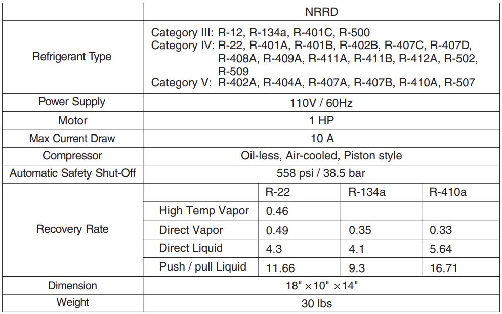
SPECIFICATIONS

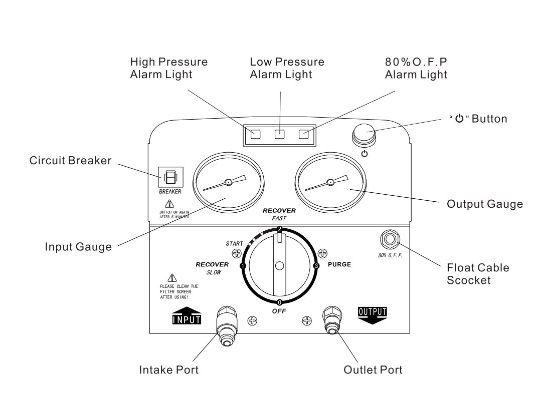
CONTROL PANEL
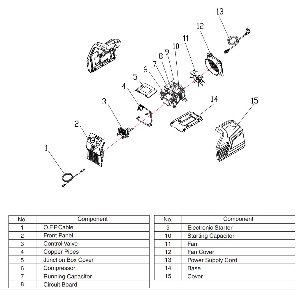
PARTS DIAGRAM
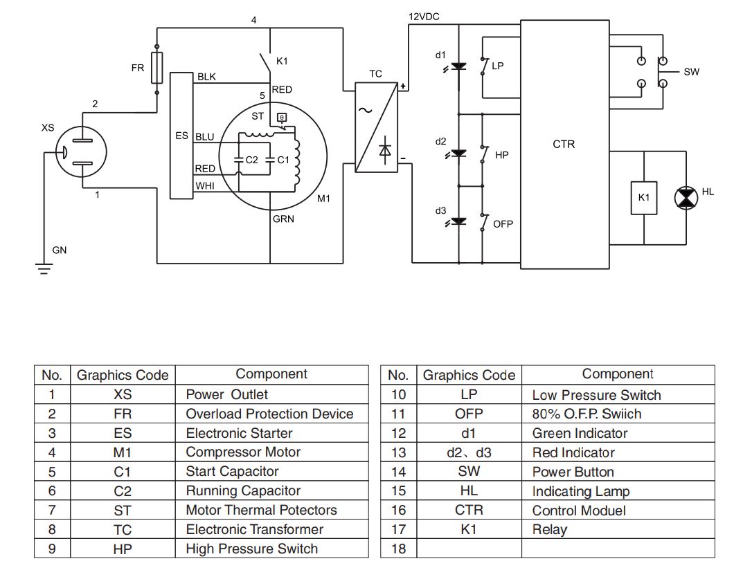
WIRING DIAGRAM
OPERATING INSTRUCTIONS
1. Initial Purge
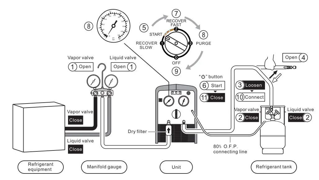
Initial Purge
- Connect hoses correctly and tight according to setup diagram.
- Open the vapor and liquid valves of manifold gauge.
- Disconnect hose from refrigerant tank.
- Open the output valve.
- Turn the switch to START.
- Press button.
- Turn the switch to position 2 and start purging the air out of the hoses.
- While the input gauge getting to 15″ of vacuum (-1 bar), turn the switch to position 3 to start self-purge.
- While the input gauge getting to 15″ (-1 bar) again, turn the switch to position 0 to finish self-purge.
- Connect the hose back to refrigerant tank.
- Press button.
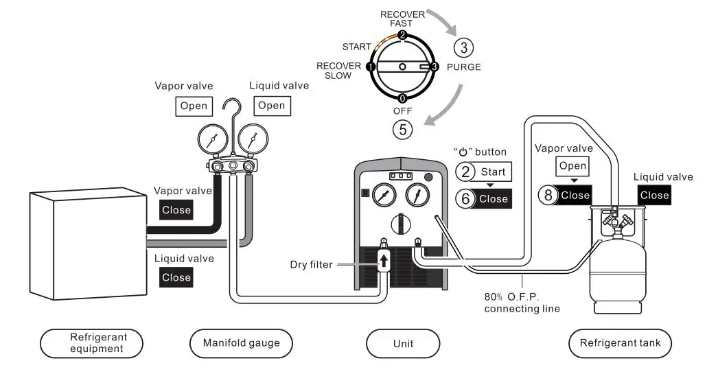
2. Recovery Process
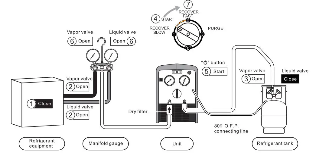
Recovery Procedure
- Connect hoses correctly and firmly. (Please refer to the setup diagram)
- Make sure all valves are closed.
- Turn off the power to system equipment.
Start Operation
- Open the vapor and liquid valves of refrigeration or air conditioning system equipment.
- Open the vapor valve of the refrigerant tank.
- Turn the switch to the position START.
- Press button.
- a. Open the liquid valve for liquid recovery.b. Open the vapor valve for vapor recovery.
- Turn the switch slowly to position 2 for faster recovery.
- When the recovery is finished, the unit gets to the required vacuum or automatically stops by low pressure protection.
![]() Note
Note
- If compressor liquid slugging occurs at position 2, turn the switch to position START until the liquid slugging stops.
- If the recovery restarts after interruption of power or fails to start,2.1 Turn the switch to position START, turn on the power switch, press START button for liquid recovery.2.2 Turn the switch to position 3,turn on the power switch, press START button for vapor recovery.
![]() Note
Note
- Turning the switch to position 1 gets a stable recovery of liquid with low speed of 2.6 lbs./Min.
- If compressor slugging occurs at the position 1 turn the switch slowly to position START until slugging stops. Make sure the pressure is at zero, because it doesn’t work at 10.
- There is no need to turn off the power and it can do the self-purge cycle automatically.
3. Self-purge Process
![]() NoticeThe unit must be purged after each use; Liquid refrigerant remained may expand and damage the components and pollute the environment.
NoticeThe unit must be purged after each use; Liquid refrigerant remained may expand and damage the components and pollute the environment.
Self-purge Procedure
- The unit stops automatically when recovery is finished.
- Press button.
- Turn the switch slowly to position 3 to start purge.
- When the self-purging cycle is finished, the unit goes into a vacuum.
- Turn the switch to position off.
- Press button.
- Close the check valve to hoses. 8
- Turn off the vapor valve of refrigerant tank.
4. Push/Pull Mode
![]() NoticeAn electric scale is needed to monitor the recover process to prevent overfilling.
NoticeAn electric scale is needed to monitor the recover process to prevent overfilling.
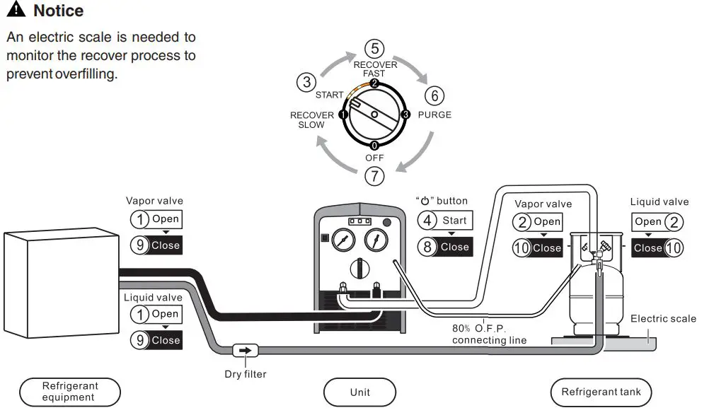
Liquid Push/Pull Mode
- Connect the hoses correctly and firmly. (Please refer to the connection diagram)
- Make sure all valves are closed.
Start operation
![]() WarningWhen the electric scale shows that the refrigerant in the tank has reached 80% capacity, turn the power off and close the tank valves.
WarningWhen the electric scale shows that the refrigerant in the tank has reached 80% capacity, turn the power off and close the tank valves.
- Open the vapor and liquid valves of the system equipment.
- Open the vapor and liquid valves of the recovery tank.
- Turn the switch to position START.
- Press button.
- Turn the switch to position 2 to start push/pull mode. When the display of electric scale stops rising or increases very slowly, it means the liquid recovery is finished, and it is time to switch to vapor recovery.
- Turn the switch to position PURGE and follow self-purge mode instructions to purge the refrigerant vapor.
- Turn the switch to position OFF.
- Press button.
- Close the vapor and liquid valves of the system equipment
- Close the vapor and liquid valves on the recovery tank.
- Connect the hoses again and recover the vapor from the system equipment according to recovery mode instructions.
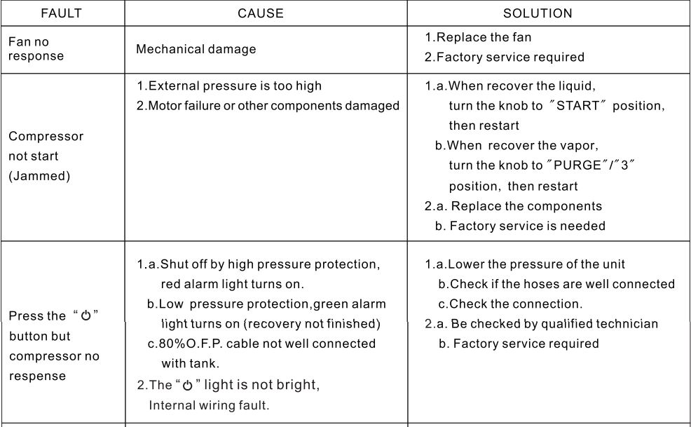
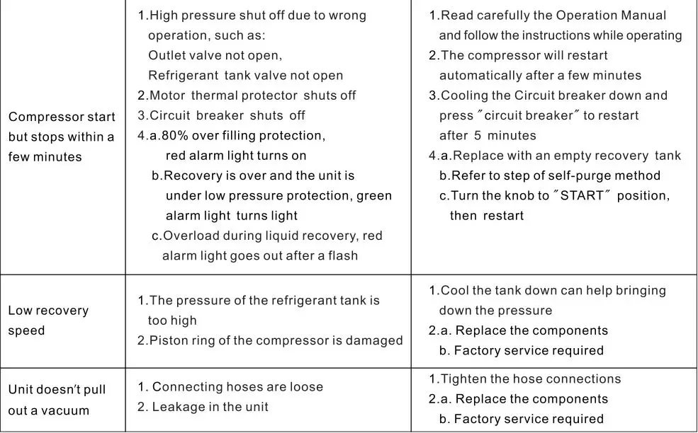
TROUBLESHOOTING
_______________________________________________________________________________________________________________________________________________________________________________________________________________________________________________________________________________________________________________________________________________________________________________________________________________________________________
NAVAC Inc.www.NavacGlobal.comTel/Fax: +1 877 MY-NAVAC877 696 2822MADE IN CHINA
References
[xyz-ips snippet=”download-snippet”]