![]() SUNCONTROL2
SUNCONTROL2
User manualValid for the following modelsSC320MSC350M
INSTRUCTIONS FOR THE PROPER DISPOSAL  This electronic product is subject to the European Directive 2012/19 / EU. Comply with local waste disposal regulations, do not dispose of old products with normalhousehold waste. The proper disposal of products that can no longer be used prevents potential negative consequences for the environment and for the population.

Safety instructions
- Child Safety: Keep the device Out of Reach.
- Carefully check the integrity of the device and connectors.
- To avoid overheating and possible fires do not install the device in a sealed environment, Always choose a well-ventilated area.
- Do not place the device on highly flammable surfaces or environments (eg: paper, cloth, etc.).
- Do not cover the cooling slots on the side and the fan on the top.
- Do not install the device near flooded batteries: they produce flammable, corrosive, and explosive gas while working, and it can damage the product.
- protect the device from sunlight or direct sources of heat.
- To avoid malfunctions, DO NOT install and use the device in very humid environments, in contact with water splashes, various liquids, or exposure to rain.
- To avoid the risk of electric shock and/or fire, the vehicle’s fuel system must be in good condition.
- In case of damaged connecting cables or inadequate sections, immediately replace them with suitable cables as specified by this manual or by a qualified electrician.
- In case of anomalies in the conformity of the product do not use it! it is strictly forbidden to open the device. Repairs may only be carried out by qualified technical personnel using original spare parts.
- Keep the instruction manual near the device for easy access to the essential safety, use, and maintenance information.
- The information contained in this manual may be changed without notice. NDS Energy s.r.l. reserves the right to make changes and improvements to the product at any time without notice and without obligation to apply these changes to the devices previously distributed.
- The images of the products are purely indicative and may therefore not be fully representative of the
characteristics of the product, differing in color, size, or accessories.
Package contents
Check the contents of the package:
- N°1 SUNCONTROL2
- N° 1 Replacement fuse
- Wall mounting screws
DESCRIPTION
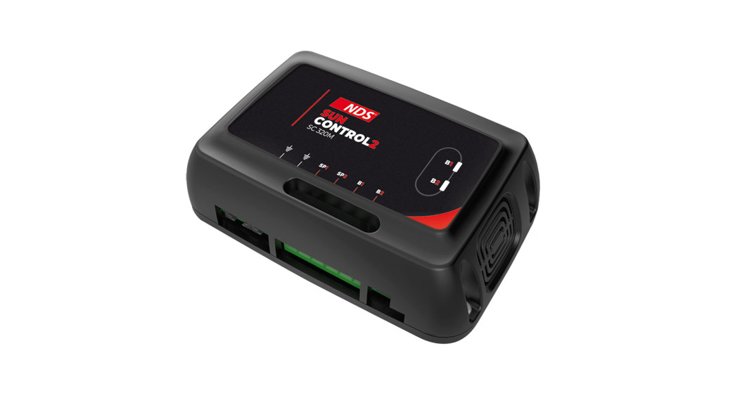
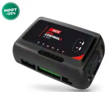
SUNCONTROL2, the automatic solar regulator with MPPT technology to pushes the efficiency of photovoltaic modules to the maximum: more energy, less space.The MPPT algorithm always uses the “maximum power peak” delivered by the panel, with a significantly higher performance than the PWM technology (up to 25% more).SUNCONTROL2, available in two models SC320M and SC350M, manages (depending on the model), up to 350W input, with a maximum charge of 25A. The new microprocessor, equipped with OPTICHARGE firmware, performs up to 6 charging phases, including desulphation and maintenance phases, for optimal recharging of theon-board batteries.SUNCONTROL2 is compatible with the following battery technologies: Free Acid, GEL, AGM, and LiFePO4 and both the leisure batteries and the starter battery can be recharged.The state of charge (SoC) of both connected batteries is immediately visible on top of the device thanks to the two multicolored LEDs.The system works with a 12V nominal voltage and it is possible to connect two photovoltaic panels, on separate inputs, with a maximum power of 180Wp (depending on the model).The Dip Switch selector, located next to the power connections, allows you to select the output charge curve in a simple and fast way.The touch screen displays DT002 (optional) with new management software, allowing you to view the charge information and set the various settings with the new communication protocol NDS.MAIN FEATURES
- MPPT technology (+25% performances)
- Charging curve selection: Wet, GEL, AGM e LiFePO4
- New Firmware OPTICHARGE
- Up to 6 charging phases
- Starting battery charge
- Desulphation curve
- Independent inputs for 2 solar panels
- SoC Quick view with status LEDs.
- Touch screen Display (Optional)
operations
SUNCONTROL2, charges up to two batteries: one service battery (B1) and one starter battery (B2), with priority charging to the service battery.SUNCONTROL2 will start charging the batteries if the following conditions are satisfi ed:
- The connected Solar Panels deliver a voltage 1V higher than the voltage of the batteries to be recharged.
- The battery voltage is higher than 8V.
The Leisure Battery will be charged with the selected curve.The Starting Battery will be charged if the following conditions are satisfied:
- Leisure battery charged between 80% and 100%.
- Starting battery with voltage under 12,5V.
Every charging phase has a maximum run time, with the exception of the maintenance phase, which constantly monitors the state of charge and, if necessary, delivers an impulse current to keep the battery 100% charged.NOTEIf the photovoltaic panels interrupt the power supply (during the night, shadowed solar panel, etc. …) the system goes into StandBy mode: LEDs off and self-consumption to the minimum (<2mA).
installation
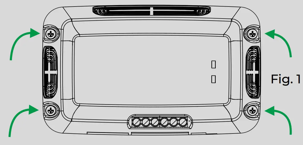
Place the SUNCONTROL2 on the chosen surface and secure the entire device using the fixing holes integrated into the shell with the supplied screws or equivalent (Fig.1).
All electrical and setup connections are on the front, it is not necessary to disassemble the plastic shells, except for the protection fuse replacement.On the front side, after the power connections, there’s a Dip Switch for the charging curve selection, it’s important to select the correct curve according to the type of battery supplied, for the selection of the correct curve please refer to the chapter “Charging curve selection”.NOTEThe optional DT002 display allows you to change parameters and charging curves. If connected, the display will receive the parameters set on the Dip Switch, further changes will be made only on the display DT002.
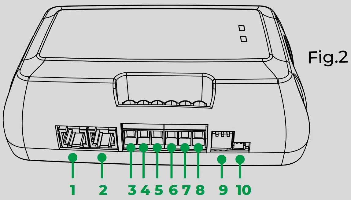
| N° PIN | CONNECTION |
| 1 | Display Connection |
| 2 | Secondary connection (for future connections) |
| 3 | Solar Panel Negative poles |
| 4 | Batteries Negative poles |
| 5 | Solar Panel 1 Positive pole |
| 6 | Solar Panel 2 Positive pole |
| 7 | Leisure battery Positive pole (B1) |
| 8 | Starting battery Positive pole (B2) |
| 9 | Dip Switch – Charging curve selection |
| 10 | Temperature sensor connection for B1 (optional) |
CAUTION
- For electrical connections, use cables of appropriate cross-section: from 6 mm2
- In case of a long stay, it is advisable to disconnect the negative cable from the device to completely neutralize any residual consumption that may inadvertently discharge the leisure battery.
charging curve selection
The Dip Switches, located next to the power connections, allow you to select the proper charging curve for the installed services battery, use the table to set the correct curve for your battery. The Dip Switches affect the B1 charging curve (leisure battery), not B2 (starter battery). The B2 charging curve is preset to curve N°4 (wet – desulphation OFF).
|
CURVENUMBER |
SWITCH SETTING | CURVE TYPE |
CHARGING DATA |
| 0 |  |
GELDesulphation OFF |
Vmax = 14,3VVmaint = 13,6V |
| 1 | 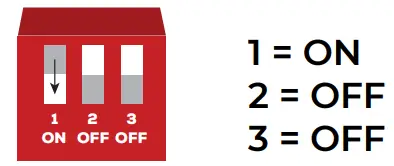 |
GELDesulphation ON |
Vmax = 14,3VVmaint = 13,6VVdes= 15,8V |
| 2 | 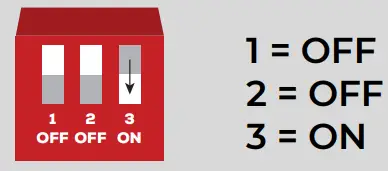 |
AGMDesulphation OFF |
Vmax = 14,8VVmaint = 13,8V |
| 3 | 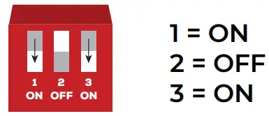 |
AGMDesulphation ON |
Vmax= 14,8VVmaint = 13,8VVdes = 15,8V |
| 4 | 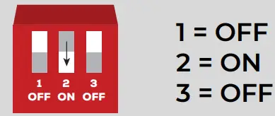 |
WetDesulphation OFF |
Vmax= 14,4VVmaint = 13,5V |
| 5 | 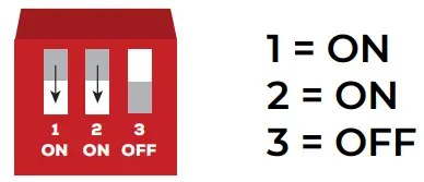 |
WetDesulphation ON |
Vmax= 14,4VVmaint = 13,5VVdes = 15,8V |
| 6 |  |
LiFePO4 LithiumMaintenance OFF |
Vmax= 14,6V |
| 7 | 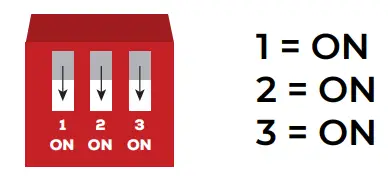 |
LiFePO4 LithiumMaintenance ON |
Vmax= 14,6VVmaint= 13,7V |
NOTE
- The default setting is Curve 0, for GEL batteries – desulphation OFF.
- In order to safeguard the battery, with an ambient temperature below 0°C, the LiFePO4 charge curve will not be started.
CHARGING CURVE
|
B1 – PHASE DISCUSSION |
|
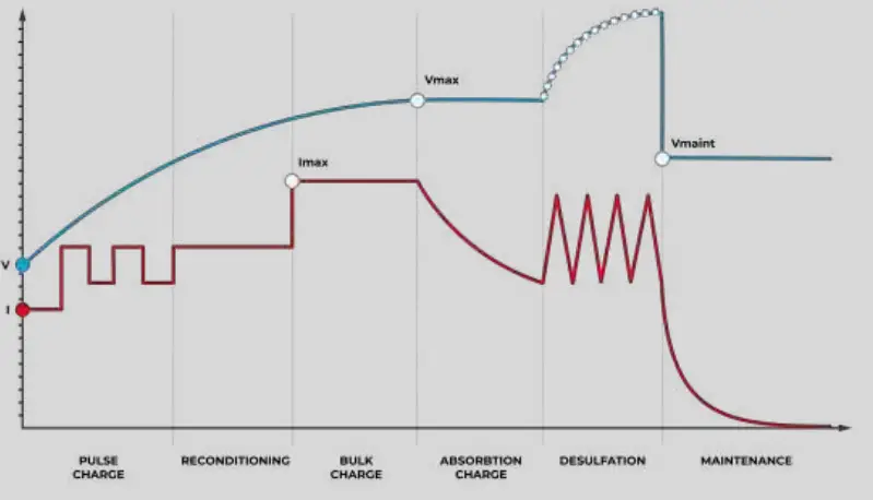
| PULSE CHARGE | With voltage between 8V and 10.5V, a current between 1A and 2A will be delivered, every 5 seconds. Timeout 4 hours. |
| RECONDITIONING | With voltage between 10.5V and 12.0V, an approximately 2A constant current will be delivered.Timeout 8 hours. |
| BULK CHARGE | With voltage between 12V and Vmax (Maximum voltage of the selected charging curve), will be delivered a constant current of 20A model SC320M and 25A model SC350M. |
| ABSORPTION CHARGE | With battery voltage equal to Vmax (Maximum voltage of the selected charging curve), will be delivered a constant Voltage equal to the selected curve Vmax. The delivered current will decrease as the battery state of charge increases to about 3A.Timeout 6 hours. |
| DESULPHATION (ONLY IF SELECTED) | An approximately 2A constant current will be delivered, allowing the battery voltage to rise independently to the maximum value of 15.8V. This phase ends with the achievement of 15.8V. Timeout 2 hours. |
| MAINTENANCE | This phase keeps a constant voltage related to the selected charging curve (Vmaint). This phase has a 4 hours timeout for the LiFePO4 charging curve with maintenance ON (curve N°7), while for the other curves there’s no time limit. If during the maintenance phase the voltage should fall below 13.15V for LiFePO4 curve and 12.65V Wet curve and 12.8V and for the other curves, the charge will be restarted from the first phase. Timeout 4 hours. |
|
B2 – PHASE DISCUSSION |
|
| PULSE CHARGE | With voltage between 8V and 10.5V, a variable current between 1A and 2A, every 5 seconds.Timeout 4 hours. |
| RECONDITIONING | With voltage between 10.5V and 12.0V, an approximately 2A costant current will be delivered.Timeout 8 hours. |
| BULK CHARGE | With battery voltage between 12V and 14,4V, will be delivered a 5A constant current. |
| ABSORPTION CHARGE | With battery voltage, 14,4V will be delivered at a 14,4V constant voltage. The delivered current will decrease as the battery state of charge increases to about 3A. Timeout 6 hours. |
| MAINTENANCE | This phase keeps a constant voltage of 13,5V.Timeout 8 hours. |
Led indicators
The two LEDs on the upper part of the device marked B1 and B2, allow you to quickly understand the charge status of the connected battery.Each LED can emit different colors referred to a precise state of charge of the battery, the table below explains the relationship between the LED color and the battery state of charge.
| SIGNAL | MEANING |
| Red LED | Charging |
| Orange LED | Reconditioning |
| Green LED | Fully charged / Maintenance |
CAUTIONA fast flashing of both LEDs (with the solar panel active) shows an error due to the internal fuse breaking, or services battery voltage below 6V.
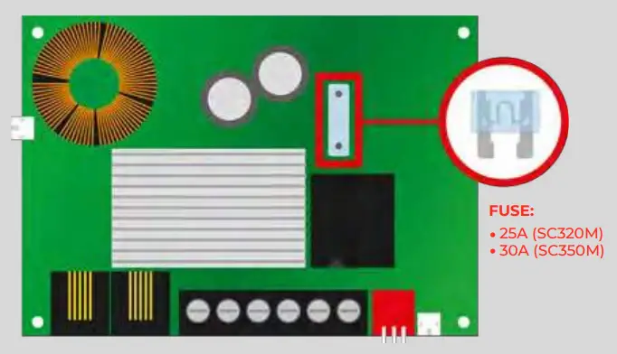
Fuse replacement
If the protective fuse on the SUNCONTROL2 electronic board is damaged, it can be replaced with the original replacement fuse (supplied) or with a common 25A (for SC320M) or 30A (for SC350M) automotive fuse.
 report this ad
Follow these steps to reach the fuse:
- Remove SUNCONTROL2 from its housing.
- Rotate the device to reveal the screws on the bottom of the device.
- Unscrew the 4 screws.
- Remove the front shell of SUNCONTROL2 to access the fuse.
- Replace the fuse.
Technical features
|
DESCRIPTION |
SC320M |
SC350M |
|
INPUTS |
||
| Maximum input Voltage solar panels (open circuit voltage) | 29,5V | 29,5V |
| Solar Panel input Connections | 2 | 2 |
| Solar Panel input Maximum Power Supported | 50W – 160W | 50W – 180W |
|
OUTPUT B1 |
||
| Battery nominal voltage | 12V | 12V |
| Charging current maximum output | 20A | 25A |
| Minimum battery capacity required Lead-acid | 60Ah | 80Ah |
| Minimum battery capacity required LiFePO4 | 40Ah | 50Ah |
| Mimumum battery voltage required | 8V | 8V |
| Charging curve selector/Curves number | Yes/8 | Yes/8 |
| Temperature regulated fan speed | No | Yes |
| Temperature regulated charging (by temperature sensor for B1 battery – optional) | Yes/-30mV/°C | Yes/-30mV/°C |
|
OUTPUT B2 |
||
| Battery nominal voltage | 12V | 12V |
| Charging current maximum output | 5A | 5A |
| Minimum battery capacity required Lead-acid/LiFePO4 | 15Ah/10Ah | 15Ah/10Ah |
| Minimum/maximum voltage starting charge | 8V / 12,5V | 8V / 12,5V |
| Maximum charging voltage | 14,4V | 14,4V |
| Temperature regulated fan speed | No | Yes |
| Maximum charging timeout | 8h | 8h |
|
GENERAL |
||
| Charging algorithm OPTICHARGE | Yes | Yes |
| Stand-by self-consumption | <2mA | <2mA |
| Display connection | Yes | Yes |
| Internal protection fuse | 25A | 30A |
| Reverse polarity protection | Yes | Yes |
| Night-time discharge protection | Yes | Yes |
| Overload protection | Yes | Yes |
| Overheating protection (output power reduction) | Yes | Yes |
| Size (mm) | 123 x 108 x 50 | 123 x 108 x 50 |
| Weight (cables excluded) | 400g | 420g |
| Working temperature | -20°C/+50°C | -20°C/+50°C |
| Ambient humidity | <90% no condensation | <90% no condensation |
| Maximum altitude |
3000m(maximum nominal output up to 2000m) |
3000m(maximum nominaloutput up to 2000m) |
F.A.Q.
- About solar panels, what’s the maximum voltage supported by SUNCONTROL2?The maximum supported voltage is 29,5V.
- Is it possible to connect one 200W solar panel only, on a single SUNCONTROL2 connection?It’s possible to connect just one bigger solar panel (200W), for example on SUNCONTROL2 Pin N°5, but you must connect Pin N°5 and Pin N°6. Use, at least, a 6 mm 2 cross-size cable.
- Is it normal to have a battery voltage (with solar regulator working) over 15V?It’s normal when the device is in desulphation mode.It is possible to turn OFF the desulphation selecting the proper charging curve: look at the chapter “Charging curve selection”.
warranty
![]() Tutta l’energia che ti serveall the energy you need
Tutta l’energia che ti serveall the energy you need NDS ENERGY s.r.l.Via Pascoli, 16965010 Cappelle sul Tavo (Pe) ItalyTel.:+39 085 4470396web: www.ndsenergy.itemail: [email protected]
 LIKE US: facebook.com/ndsenergysrl0037_MANB_Sc320_Sc350_GB02
References
[xyz-ips snippet=”download-snippet”]