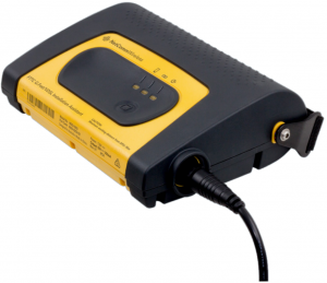
NetComm FTTC G.Fast VDSL Installation Assistant

This quick start guide provides an introduction to the FTTC G.Fast/VDSL Installation Assistant. The FTTC G.Fast/VDSL Installation Assistant is used to power an FTTC DPU and allows technicians to configure and perform diagnostics on an FTTC DPU.
Package contents
The NDD-0203-02 FTTC G.Fast/VDSL Installation Assistant package includes:
|
|
||
|
|
|
|
|
|
|
|
|
|
|
|
 1 x Battery pack (Li-ion,10.4 Ah, removable)
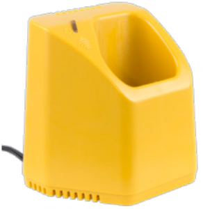 1 x Battery charger(12 V DC)
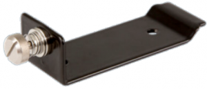 1 x Battery chargermounting bracket
 1 x 12 V DC Charge lead with cigarette lighter plug
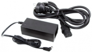 1 x 240 V AC to 15 V DC adapter with IEC-C7 cable
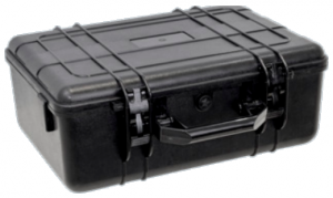 1 x Carry case
 1 x Magnetic wand
 1 x Quick Start Guide
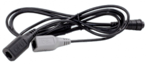 1 x Dual RJ11 lead
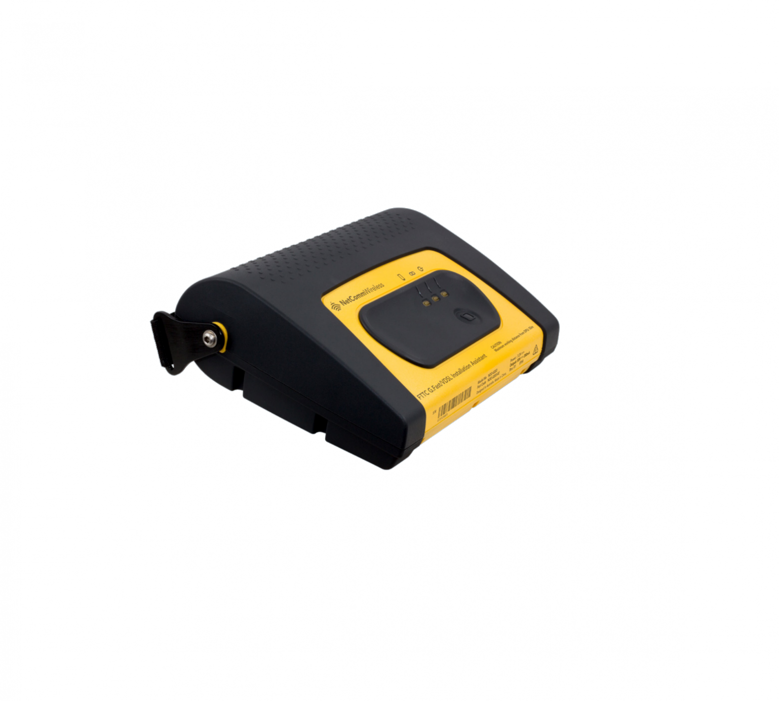
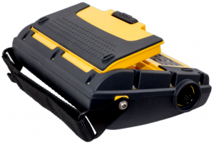
Device overview
| ITEM | |
| 1 | Power button |
| 2 | LED indicators |
| 3 | Output port (used with Dual RJ11 lead) |
| 4 | Battery compartment cover |
| 5 | Carry strap |

LED indicators
The LED indicators provide you with information about the power, connection and remaining battery level of the device
|
LED DESCRIPTION |
COLOUR |
FUNCTION |
| Power Status |
|
Displays the power (ON/OFF) status of the Installation Assistant. |
| Link Status | Displays the connection status between the FTTC DPU and the Installation Assistant. Also displays fault states. See the table below for further detail. | |
| Battery Status |
|
Displays battery life status. |
 Red / Amber / Green
 Link Status LED
The Link Status LED indicator is a bi-colour (red/blue) indicator which displays the status of the power link with the FTTC DPU.
|
COLOUR |
STATE |
STATUS |
|
|
Blinking one time per second | Start up phase. |
|
|
On | Connected and power feed active |
|
|
Blinking one time per second | Line fault – short circuit or overcurrent |
|
|
Blinking four times per second | Line fault – foreign voltage detected |
|
|
On | Line fault – FTTC G.Fast/VDSL Installation Assistant overheated |
|
|
Blinking one time per second, alternating colours | Line fault – off-hook telephone detected, find and disconnect telephone or other device connected to your phone line |
 Red
Red Battery Status LED
| COLOUR | STATE |
STATUS |
|
|
Blinking one time per second | < 10% |
|
|
On | 10 – 30% |
|
|
On | 30 – 60% |
|
|
On | 60% – 100% |
 Note: We recommend that you do not begin an installation if the battery charge level is below 10%.
Audible Alerts
| ALERT |
STATUS |
| Single short beep | Power button push |
| Single short beep every 5 seconds | Low battery (<10%) |
| Three short beeps | Reverse power feed negotiation complete |
| Long beep (2 seconds) | Line fault (e.g. Off-hook, foreign voltage, over current) |
Getting started with the Installation Assistant
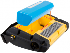
- Push the retaining clip up and then lift as shown in the image below to remove the battery compartment cover.
- Insert the battery pack into the battery compartment as shown below, taking care to align it correctly, then replace the battery compartment cover.
- Place the carry strap over your wrist. Adjust the strap by lifting the Velcro and tightening it so that the unit is secure.
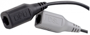
- Connect the round end of the dual RJ11 lead to the output port of the Installation Assistant and turn the cable gland clockwise to lock it in place.
- Connect the pre-wired line of the FTTC DPU to the black DPU port of the dual RJ11 lead.
- For DSL diagnostics, connect a DSL test tool to the grey DSL port of the dual RJ11 lead.
- Push the power button on the top panel of the Installation Assistant once. The unit beeps once and the power LED lights up blue to indicate the Installation Assistant has turned on. The DPU takes approximately 10 minutes to pre-charge.Once connected and powering the DPU, the Installation Assistant beeps three times and the Link Status LED turns solid blue to indicate that the reverse power feed negotiation is complete. The FTTC DPU then begins bootup which takes approximately 2 minutes.When it has completed booting, you may begin diagnostics. When you have finished performing diagnostics, press and hold the power button for 3 seconds to turn off the Installation Assistant.
Note: The FTTC G.Fast/VDSL Installation Assistant has a maximum operating distance of 50 metres, hence it is not intended for use inside a customer’s premises.If the power connection has not successfully negotiated within 15 minutes, the FTTC G.Fast/VDSL Installation Assistant powers off automatically.When packing up the FTTC G.Fast/VDSL Installation Assistant, carefully place all items in the carry case so that the case can be closed easily. Do not force the case shut.
Using the magnetic wand
The FTTC DPU features a magnetic service button which is used with the magnetic wand to trigger the following functionality:
![]() A short hold with the magnetic wand reactivates the LED indicators for 10 minutes (1 to 10 seconds magnet proximity).
A short hold with the magnetic wand reactivates the LED indicators for 10 minutes (1 to 10 seconds magnet proximity).![]() A medium hold with the magnetic wand reboots the FTTC DPU (11 to 20 seconds magnet proximity).
A medium hold with the magnetic wand reboots the FTTC DPU (11 to 20 seconds magnet proximity).![]() A long hold with the magnetic wand restores factory default settings (21 to 22 seconds magnet proximity).
A long hold with the magnetic wand restores factory default settings (21 to 22 seconds magnet proximity). To perform the above functions, place the magnetic wand on the magnetic service button of the FTTC DPU’s panel.
|
ACTION |
SWITCH ACTIVATION WINDOW TIME |
LEDS FLASHING |
|||||
|
MIN (SECONDS) |
MAX (SECONDS) | FIBRE | LINE 1 | LINE 2 | LINE 3 |
LINE 4 |
|
| Reactivate LED indicators |
1 |
10 |
 |
|
|||
| Reboot |
>10 |
20 |
|
|
|
||
| Restore Factory Default settings |
>20 |
22 |
|
|
|
|
Charging the battery
- Place the battery in the charger as shown below. The battery may only be inserted into the charger in one direction.
- The Installation Assistant package includes both a 12 V DC Charge lead with cigarette lighter plug and a 240 V AC to 15 V DC adapter which can be used to power the charger. Connect the appropriate charger as shown below. Note: When using the charger in a vehicle, the charger will stop charging when the car battery reaches 12 V. To avoid draining the car battery, we recommend only charging the battery when the engine is running.
- The LED flashes green to indicate that the battery is being charged. When it stops flashing and displays as solid green, remove the battery. The battery takes approximately 7 hours to fully charge from empty
Charger Status LED
The charger features a single bi-colour (red/green) LED indicator. See the table below for a description of each status of the LED indicator.
|
COLOUR |
STATE |
STATUS |
|
|
On | Charger powered on. No battery |
|
|
Blinking once per second | Fault (Battery overheated, battery fault, or charger voltage too low) |
|
|
Blinking once per second | Charging |
|
|
On | 100% charged |
 Green
GreenCharging time and battery life
The battery takes approximately 7 hours to charge from 0-100%. A fully charged battery can power the device for more than 5 hours of constant operation.Battery packs have a finite lifespan and should be replaced after 2-3 years or when they no longer hold an acceptable charge level.
 Warning: Risk of explosion if battery is replaced by an incorrect type.
Important Notice: Dispose of used batteries according to the instructions. For more details, see the Product handling section.
Mounting the charger
To mount the charger, place screws, bolts or other fastening equipment through the holes on the mounting bracket. The dimensions of the holes are given below.
Ensure that you leave at least 157mm from the top of the charger to allow the battery to be inserted and removed.
Ordering additional parts
If you require additional parts, contact your sales representative and quote the following part numbers:
| PART NUMBER | PART NAME |
| CBL-0094-PKG | FTTC Dual RJ11 lead |
| BAT-0005-PKG | FTTC Battery pack |
| HDW-0067-PKG | FTTC Magnetic wand |
| HDW-0062-PKG | FTTC Battery charger pack |
DPU Troubleshooting
DPU is not powering up
- Only use the FTTC Installation Assistant to power up the DPU. The Network Connection Device (NCD) must not be used in the field for installation.
- Check the ports of the Y-cable and the RJ-11 plug from Line 1 of the DPU.
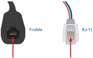
There should be no dirt or dust obstructing the connecting pins. If pins are dirty, clean them with compressed air.Pins should be straight and not bent. If they are bent, order a replacement Y cable.
- Check that the DPU is connected to the DPU port of the Y-cable. The DPU end of the Y-cable is BLACK.
- If the DPU powers up and won’t attach to the OLT, check that the fibre connector is clean.

Safety and product care
Warning: This is a class A product. In a domestic environment, this product may cause radio interference in which case the user may be required to take adequate measures.
Electrical Safety
AccessoriesOnly use approved accessories. Do not connect with incompatible products or accessories.
Product handlingYou alone are responsible for how you use your device and any consequences of its use.Use of your device is subject to safety measures designed to protect users and their environment.
- Always treat your device and its accessories with care and keep it in a clean and dust-free place.
- Avoid exposing the device and its accessories to direct sunlight for prolonged periods.
- Do not expose the device or its accessories to open flames or lit tobacco products.
- Do not expose any of the accessories to liquid, moisture or high humidity.
- Do not drop, throw or try to bend your device or its accessories.
- Do not use harsh chemicals, cleaning solvents, or aerosols to clean the device or its accessories.
- Do not paint your device or its accessories.
- Do not attempt to disassemble your device or its accessories, only authorised personnel must do so.
- Do not use or install this product in extremely hot or cold areas. Ensure that the device is installed in an area where the temperature is within the supported operating temperature ranges: In Use: (-5°C to 50°C) Charging: (0°C to 40°C)
- FTTC G.Fast/VDSL Installation Assistant IP rating: IP54
- Do not use your device in an enclosed environment or where heat dissipation is poor. Prolonged use in such space may cause excessive heat and raise ambient temperature, which will lead to the automatic shutdown of your device for your safety. To use your device normally again after such shutdown, cool it in a well ventilated place before turning it on.
- Do not operate the device where ventilation is restricted.
- Do not use or install this product near water to avoid fire or shock hazard. Avoid exposing the equipment to rain or damp areas.
- Do not cover the air vent of the battery charger while it is in use.
- Arrange cables in a manner such that they are not likely to be stepped on or have items placed on them.
- Ensure that the voltage and rated current of the power source match therequirements of the device. Do not connect the device to an inappropriate power source.
- Do not dispose of batteries in a fire, they may explode. Please check local regulations for disposal of electronic products.
- Keep away from heat and open flames. Store battery in a cool, dry place
Device heatingYour device may become warm during normal use.
ChildrenDo not leave your device and its accessories within the reach of small children or allow them to play with it. They could hurt themselves or others, or could accidentally damage the device.
Faulty and damaged productsDo not attempt to disassemble the device or its accessories.The device and its accessories do not contain any user-serviceable components.Only qualified personnel must service or repair the device or its accessories.If your device or its accessories have been submerged in water punctured or subjected to a severe fall, immediately cease using them.
NETCOMM WIRELESS LIMITED ABN 85 002 490 486Head Office, 18-20 Orion RoadLane Cove, Sydney, NSW 2066, AustraliaPhone: +61 2 8205 3888 f: +61 2 9424 2010Email: [email protected]www.netcommwireless.com

References
[xyz-ips snippet=”download-snippet”]