
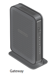
DOCSIS3.0 N900 Wireless Data Gateway CG4500BDPackage Contents
Connect the Gateway
To configure the gateway, you need a computer with DHCP enabled that has an available Ethernet port.
-
- Ensure that the gateway can be conveniently wired to the computer and is close to a power outlet.
- For better wireless performance, position the gateway vertically in the stand.
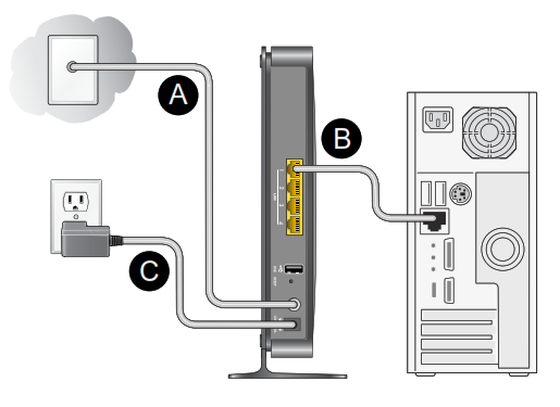
- Connect cable port on the gateway to your cable line splitter or outlet (A).Use the coaxial cable from your cable company.

- Connect your computer to the gateway with the included Ethernet cable (B).
- Connect the power adapter to the gateway (C).
- Plug the other end of the power adapter into an electrical outlet.
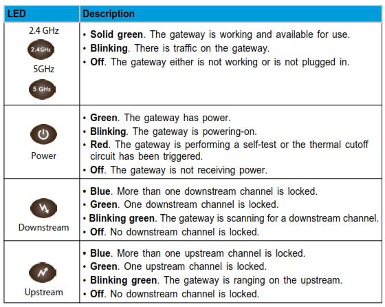
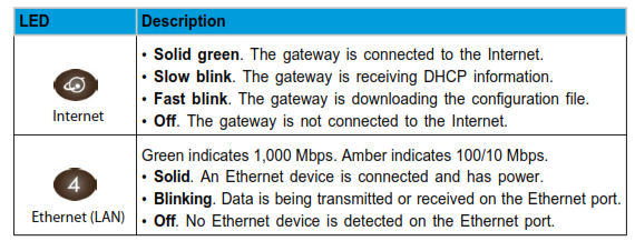
- Wait about 50 seconds for the gateway to start.The Internet LED blinks, then turns solid green, indicating that a link was established to the cable network.You can use the buttons and LEDs on the front of the gateway to check its status. For more information, see the following table and the LED table on the other side of this document.
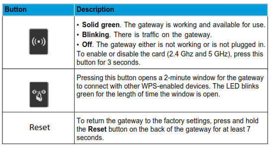
To return the gateway to its factory settings, use the end of a paper clip to press and hold the Reset button on the back of the gateway for at least 7 seconds. All LEDs simultaneously blink amber three times. The gateway resets and returns to the factory settings.
Log In to the Gateway
To log in to the gateway to view or change its settings:
-
- On a computer that is connected to the gateway with an Ethernet cable, launch an Internet browser such as Mozilla Firefox or Microsoft Internet Explorer.
- Type http://192.168.0.1 in the address field of the browser.
- When prompted to log in, enter the user name admin and its default password of password.The Product Family menu displays.
Technical Support
Contact your cable Internet service provider for technical support.
Note to CATV System InstallerPlease note, this reminder is provided to call the CATV system installer’s attention to Section 820-93 of the National Electrical Code, which provides guidelines for proper grounding and, in particular, specifies that the coaxial cable shield be connected to the grounding system of the building as close to the point of cable entry as possible.
WARNING: When installing or realigning an outside antenna system, take extreme care to avoid any contact with power lines or circuits. Contact could be fatal.
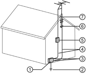
Reference to the Grounding Figure
The numbers in the figure on the right indicate:
-
-
- Electric service equipment
- Power service grounding electrode system (NEC Art 250, Part H)
- Ground clamps
- Grounding conductors (NEC Section 810-21)
- Antenna discharge unit (NEC Section 810-20)
- Ground clamp
- Antenna lead-in wire
-
NETGEAR, the NETGEAR logo, and Connect with Innovation are trademarks and/or registered trademarks of NETGEAR, Inc. and/or its subsidiaries in the United States and/or other countries. Information is subject to change without notice. © NETGEAR, Inc. All rights reserved.For indoor use only. Valid in all EU member states, EFTA states, and Switzerland.
NETGEAR, Inc.350 East Plumeria DriveSan Jose, CA 95134 USA
DOCSIS3.0 N900 Wireless Data Gateway CG4500BD User Manual – DOCSIS3.0 N900 Wireless Data Gateway CG4500BD User Manual –