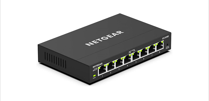

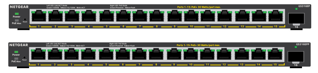
Installation Guide16-Port PoE+Gigabit Ethernet Plus Switch with 1 SFPPort (180W)GS316EP16-Port High-Power PoE+ Gigabit Ethernet PlusSwitch with 1 SFP Port (231W)GS316EPP
Package contents
• NETGEAR Gigabit Ethernet Plus Switch• Power adapter (power cable varies by region)• Wall‑mount installation kit• Rubber feet• Mounting ties (for power adapter)• Installation Guide
Register the switch
- From a computer or mobile device that is connected to the Internet, visit my.netgear.com.
- Log in to your NETGEAR account.Note: If you don’t have a free NETGEAR account, you can create one.The My Products page displays.
- From the menu on the left, select Register a Product.
- In the Serial Number field, type the serial number of your switch.The serial number is 13 digits long. It is printed on the switch label.
- From the Date of Purchase menu, select the date that you purchased the switch.
- Click the REGISTER button.Your switch is registered to your NETGEAR account.A confirmation email is sent to your NETGEAR account email address.
Connect the switch
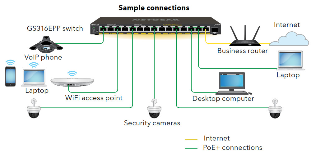
Note: We recommend that you use a Category 5e (Cat 5e) cable or higher‑rated cable for Gigabit Ethernet connections.
To use the SFP port, you must insert an SFP transceiver module, which you can purchase from NETGEAR.This switch is designed for indoor use only. If you want to connect it to a device located outdoors, the outdoor device must be properly grounded and surge-protected, and you must install an Ethernet surge protector inline between the switch and the outdoor device. Failure to do so can damage the switch.WARNING: Before connecting this switch to outdoor cables or devices, see https://kb.netgear.com/000057103 for safety and warranty information.
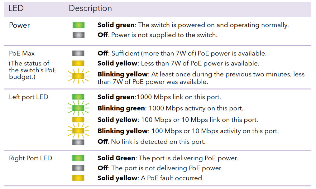
Check the LEDs
When you connect the power cord to the switch and plug it into an electrical outlet, the LEDs indicate the status:
Discover the switch’s IP address and access the switch
The NETGEAR Switch Discovery Tool (NSDT) lets you discover the switch in your network and access the local browser interface of the switch from a Mac or a Windows‑based computer.To install the NETGEAR Switch Discovery Tool, discover the switch in your network, access the switch, and discover the switch IP address:
- To download the tool, visit https://www.netgear.com/support/product/netgear-switch-discovery-tool.aspx.Download either the Mac or Windows version.
- Temporarily disable the firewall, Internet security, antivirus programs, or all ofthese on the computer that you use to configure the switch.
- Unzip the NSDT files, and click or double-click the executable file (for example, NDST‑1.2.102.exe) to install the program on your computer.You might see the tool icon appear on your Mac dock or Windows desktop.
- Reenable the security services on your computer.
- Power on the switch.
- Connect your computer to the same network as the switch.
- Open the NSDT.The initial page displays a menu and a button.
- From the Choose a Connection menu, select the network for this switch.
- Click the Start Searching button.The NSDT displays the IP addresses of the switches that it discovers.
- Click the ADMIN PAGE button.The login page or login window of the local browser user interface (UI) opens.
- Enter the default password that is printed on the switch label.
- If prompted, enter a new admin password for the switch.The Switch Information page displays, and shows the IP address assigned to the switch.
- Save the password and IP address for future use.You can now configure and monitor your switch.
Mount the switch on a wall
We recommend that you use the wall‑mount screws that are included.
- Locate the two mounting holes on the bottom panel of the switch.
- Mark and drill two mounting holes in the wall where you want to mount the switch.The two mounting holes must be 3.94 in. (100 mm) apart, center‑to‑center.
- Insert the supplied anchors into the wall and tighten the screws with a No. 2 Phillips screwdriver.Leave about 0.125 in. (4 mm) of each screw protruding from the wall so that you can insert the screws into the holes on the bottom panel.
Note: The screws are 6.5 mm in diameter, 16 mm in length.
PoE considerations
PoE power supplied by the switch is prioritized in ascending port order (from port 1 to port 15):• Model GS316EP ships with a 200W power adapter and can supply a total of 180W across all active PoE+ ports.• Model GS316EPP ships with a 254W power adapter and can supply a total of 231W across all active PoE+ ports.This table shows the standard power ranges without overrides applied, calculated with the maximum cable length of 328 feet (100 meters). If a device receives insufficient PoE power from the switch, consider using a shorter cable.
| Device Class | Compatible PoE Standard | Class Description | Maximum Power Supplied by the Switch | Power Delivered to the Device |
| 0 | PoE and PoE+ | Default power (full) | 15.4W | 0.44W–13.00W |
| 1 | PoE and PoE+ | Very low power | 4.0W | 0.44W–3.84W |
| 2 | PoE and PoE+ | Low power | 7.0W | 3.84W–6.49W |
| 3 | PoE and PoE+ | Mid power | 15.4W | 6.49W–13.00W |
| 4 | PoE+ | High power | 30.0W | 13.0W–25.5W |
PoE troubleshooting
Here are some tips for correcting PoE problems that might occur:
- If the PoE Max LED is solid yellow, disconnect one or more PoE devices to prevent PoE oversubscription.
- For each powered device (PD) that is connected to the switch, the associated PoE LED on the switch lights solid green. If the PoE LED lights solid yellow, a PoE fault occurred and PoE halted because of one of the conditions listed in the following table:
| PoE Fault Condition | Possible Solution |
| A PoE‑related short circuit occurred on the port. | |
| The PoE power demand of the PD exceeded the maximum level that the switch permits. The maximum level is 15.4W for a PoE connection and 30W for a PoE+ connection. | The problem is most likely with the attached PD. Check the condition of the PD, or restart the PD by disconnecting and reconnecting the PD. |
| The PoE current on the port exceeded the classification limit of the PD. | |
| The PoE voltage of the port is outside the range that the switch permits. | Restart the switch to see if the condition resolves itself. |
Support and Community
Visit netgear.com/support to get your questions answered and access the latest downloads.You can also check out our NETGEAR Community for helpful advice at community.netgear.com.
Regulatory and Legal
(If this product is sold in Canada, you can access this document in Canadian French at https://www.netgear.com/support/download/.)For regulatory compliance information including the EU Declaration of Conformity, visit https://www.netgear.com/about/regulatory/.See the regulatory compliance document before connecting the power supply.For NETGEAR’s Privacy Policy, visit https://www.netgear.com/about/privacy-policy.By using this device, you are agreeing to NETGEAR’s Terms and Conditions at https://www.netgear.com/about/terms-and-conditions. If you do not agree, return the device to your place of purchase within your return period.Do not use this device outdoors. The PoE source is intended for intra building connections only.
NETGEAR, Inc.350 East Plumeria DriveSan Jose, CA 95134, USA
NETGEAR INTERNATIONAL LTDFloor 1, Building 3University Technology CentreCurraheen Road, Cork,T12EF21, Ireland
References
NETGEAR Privacy Policy | NETGEAR
Download Center | Support | NETGEAR
Error | NETGEAR
NETGEAR Terms and Conditions | NETGEAR
NETGEAR – Common Account Management
NETGEAR Support | NETGEAR
Do I need to use a surge protector with my NETGEAR Business device? | Answer | NETGEAR Support
English – NETGEAR Communities
Regulatory | NETGEAR
[xyz-ips snippet=”download-snippet”]