
nLiGHT Power Relay Pack

SPECIFICATIONS (rPP20)
Electrical SpecificationsInput Ratings 120-277VACMaximum Load 20A general-purpose, tungsten, and standard ballast; 16A electronic ballastDimming Load Sinks 100mA; 0-10VDC dimmable ballasts or LED drivers; “D” 0-10V leads Class 1, “DS” 0-10V leads Class 2Minimum Load NoneClass Rating 0-10V Dimming can be wired Class 1 or 2
MechanicalMounting 1/2″ Knockout (7/8″ hole)Connection Type Line and Low Voltage Leads
EnvironmentalWarrantied Operating Temperature -10°C to 60°C up to 5 amps; -10°C to 50°C up to 20 ampsStandards/ Ratings RoHS, UL 916, UL 924 (optional), FCC / IC / IFETEL
FCC ID: 2ADCB-RMODIT IC: 6715C-RMODIT IFETEL: RCPACRM18-1879 Acuity Brands Lighting Inc. RMODITThis device complies with Part 15 of the FCC Rules. Operation is subject to the following two conditions: (1) This device may not cause harmful interference, and (2) this device must accept any interference received, including interference that may cause undesired operation.Este equipo contiene el módulo con IFT #: RCPRIBM18-1491 La operación de este equipo está sujeta a las siguientes dos condiciones: (1) es posible que este equipo o dispositivo no cause interferencia perjudicial y (2) este equipo o dispositivo debe aceptar cualquier interferencia, incluyendo la que pueda causar su operación no deseada.
IMPORTANT SAFEGUARDSWHEN USING ELECTRICAL EQUIPMENT, BASIC SAFETY PRECAUTIONS SHOULDALWAYS BE FOLLOWED INCLUDING THE FOLLOWING:
- DO NOT USE OUTDOORS.
- DO NOT MOUNT NEAR GAS OR ELECTRIC HEATERS.
- EQUIPMENT SHOULD BE MOUNTED IN LOCATIONS AND AT HEIGHTS WHERE IT WILL NOT READILY BE SUBJECTED TO TAMPERING BY UNAUTHORIZED PERSONNEL.
- THE USE OF ACCESSORY EQUIPMENT NOT RECOMMENDED BY THE MANUFACTURER MAY CAUSE AN UNSAFE CONDITION.
Changes or modifications not expressly approved by the party responsible for compliance could void the user’s authority to operate this equipment.
This device contains license-exempt transmitter(s)/receiver(s) that comply with Innovation, Science, and Economic Development Canada’s license-exempt RSS(s). Operation is subject to the following two conditions:
- This device may not cause interference.
- This device must accept any interference, including interference that may cause undesired operation of the device.”
NOTE: This equipment has been tested and found to comply with the limits for a Class B digital device, pursuant to part 15 of the FCC Rules. These limits are designed to provide reasonable protection against harmful interference in a residential installation. This equipment generates, uses, and can radiate radio frequency energy and, if not installed and used in accordance with the instructions, may cause harmful interference to radio communications. However, there is no guarantee that interference will not occur in a particular installation. If this equipment does cause harmful interference to radio or television reception, which can be determined by turning the equipment off and on, the user is encouraged to try to correct the interference by one or more of the following measures:1. Reorient or relocate the receiving antenna.2. Increase the separation between the equipment and receiver.3. Connect the equipment into an outlet on a circuit different from that to which the receiver is connected.4. Consult the dealer or an experienced radio/TV technician for help.

WARRANTY 5-year limited warranty. Full warranty terms located at: www.acuitybrands.com/CustomerResources/Terms_and_conditions.aspxNOTE: Specifications subject to change without notice. Actual performance may differ as a result of the end-user environment and application.
- To reduce the risk of death, personal injury, or property damage from fire, electric shock, falling parts, cuts/abrasions, and other hazards please read all warnings and instructions included with and on the fixture box and all fixtures labels.
- Before installing, servicing, or performing routine maintenance upon this equipment, follow these general precautions.
- Installation and service should be performed by a qualified licensed electrician.
- Maintenance should be performed by a qualified person(s) familiar with the products’ construction & operation & any hazards involved. Regular maintenance programs recommended.
- To be installed to a circuit with overvoltage control to Overvoltage category Cat.III or less, minimum suppression rating 6.0 kV for a 600 V ac RMS system voltage
- DO NOT INSTALL DAMAGED PRODUCTS! This product has been properly packed so that no parts should have been damaged during transit. Inspect to confirm. Any part damaged or broken during or after assembly should be replaced.
![]() CAUTION: RISK OF PRODUCT DAMAGE
CAUTION: RISK OF PRODUCT DAMAGE
✓ Electrostatic Discharge (ESD): ESD can damage the product(s). Personal grounding equipment should be worn during all installation or servicing of the unit.✓ Do not touch individual electrical components, as this can cause ESD and affect product performance.✓ Do not stretch or use cable sets that are too short or are of insufficient length. Do not tamper with contacts.✓ Do not modify the product.✓ Do not change or alter internal wiring or installation circuitry. Do not use the product for anything other than its intended use.
WARNING – RISK OF ELECTRIC SHOCK✓ Disconnect or turn off the power before installation or servicing.✓ Verify that supply voltage is correct by comparing it with the product information. ✓ Make all electrical and grounded connections in accordance with the National Electrical Code (NEC) and any applicable local code requirements.✓ All wiring connections should be capped with UL-approved recognized wire connectors.✓ All unused connector openings must be capped.
WARNING – RISK OF BURN or FIRE✓ Do not exceed maximum wattage, ratings, or published operation conditions of the product.✓ Do not overload.✓ Follow all manufacturer’s warnings, recommendations, and restrictions to ensure proper operation of the product.CAUTION – RISK OF INJURY✓ Wear gloves and safety glasses at all times when installing, servicing, or performing maintenance.
OVERVIEW
nLight AIR rPP/rPP20 is a device that provides on/off switching and dimming for light fixtures. It is suitable for the control of commercial and industrial light fixtures in indoor environments. When installed as part of a nLight AIR lighting control system, the rPP/rPP20 will respond to wireless commands from other devices, to be programmed during startup.
INSTALLATION INSTRUCTIONS
REQUIRED TOOLS & SUPPLIES
- Electrical Pliers
- Screwdriver
 Wire nuts
- Electrical box
- 2mm Precision Slotted Screwdriver, used for 24V terminals only
INSTALLATION STEPS
- Turn the power off at the circuit breaker.
- Install electrical box in accordance with state, local, and nationalelectrical codes and requirements.
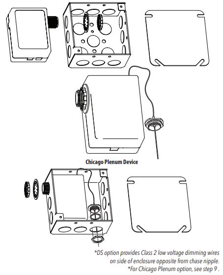
- Remove knock-out from the side of the electrical box.
- Remove retaining nut and washer from power pack mounting nipple.
- Feed Class 1* wires and mounting nipple through the knockout hole.
- Install washer and thread retaining nut onto the nipple, and hand-tighten to the wall of electrical box, then apply additional quarter-turn tightening with pliers.
- Using wire nuts, connect line, and low voltage wires as shown in the applicable wiring diagram in accordance with state, local, and national codes and requirements.
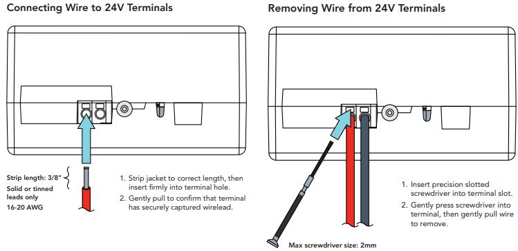
- “24V” models only: Connect +/- DC power leads from nLight AIR sensor(s) to 24VDC terminal block on side of rPP enclosure if needed. See diagrams below for additional details.
- For Chicago Plenum models only: Connect the antenna with the gasket to the inside of the sealed box, with the retaining nut on the outside of the box, as illustrated. Once installed, the antenna is IP 67 rated.
- Install electrical box cover plate before restoring power.
INITIAL OPERATION
Following power-up, the relay shall close to energize the load. The dimming output shall be at 100% light output. The device shall remain in this state until programmed with Clarity Pro mobile application. See Clarity Pro User Guide for additional programming information.
For Emergency Variant ERThe RPP/RPP20 ER version is a UL924 listed device that is powered on the Emergency circuit and provides full light output (at user-defined high-trim level) in absence of AC voltage on Normal Power sense leads. Normal operation of the control device is restored when AC line voltage is restored to the normal power sensing leads.
TROUBLESHOOTING TIPS
The device cannot be viewed in Clarity Pro
- Press the user button for a specified time to reset the device to place the device in Maintenance Mode
- Once the user-button LED confirms that the RP20 is in Maintenance Mode, open the Clarity Pro application and search for the device in Clarity Pro. a. If you still cannot see the device in Clarity Pro, contact Technical Support for additional assistance; the device may need to be replaced.
- Once the device is identifiable Clarity Pro, attempt to group or configure the device. If you are still having issues, refer to the Clarity Pro User Manual or contact Technical Support for assistance using Clarity Pro to complete the programming of your device.
For further troubleshooting guidance, please contact the Controls Technical Support Team1(800)-535-2465
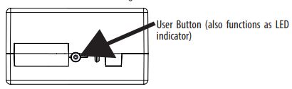
On the side of the controller is a lighted user button. This button can be used for testing and re-programming purposes.
UL924 Test (ER model only)Use this test to confirm that the lighting load is properly connected and provides the necessary output in event of loss of power.1. Press and release the button.2. Relay will close and dimming output will go to full brightness for 4 seconds.3. After 4 seconds expires, the device returns to its previous state and the indicator LED shuts off.
LED DiagnosticsThe LED is illuminated whenever the button is depressed and blinks to confirm the start of maintenance mode. Depress the button from the side to view the LED and confirm that the device is operational.
Maintenance ModeUse this mode if you are unable to Identify this device within the Clarity Pro application.1. Press and hold the button for 10 seconds, then release. LED will begin to flash rapidly after 10 seconds and stop flashing when the button is released.2. Immediately press and hold the button again for 10 seconds, then release. LED will begin to flash rapidly after 10 seconds and stop flashing when the button is released.3. The LED will flash twice to confirm entry into Maintenance Mode.
For 60 minutes, the device becomes identifiable in the Clarity Pro app and available for direct connection from mobile app to device (without requiring Group Monitor to be present, in case of a fault or connectivity issue with the Group Monitor).
Clarity Pro can then be used to perform functions such as:* Reprogram device settings* Reset device network settings* Firmware update* General troubleshooting and diagnostic functions
WIRING (DO NOT WIRE HOT)
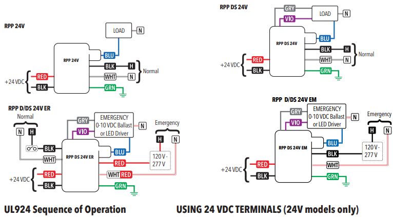 LegendRED 120-277VAC Emergency HotWHT/RED Emergency NeutralBLK Unswitched Norm. Hot*WHT Norm. Neutral*BLU Switched OutputVIO 0-10V Dim (+)GRY 0-10V Com (-)RED (Terminal) – +24VDCBLK (Terminal) – DC ComGRN Ground– Optional Test Switch (by others)* Emergency on EM devices
Do NOT wire while connected to live power, damage may occur.
ER Units: When normal power sense leads have an absence of voltageEM Units: For 90 minutes following any complete AC power interruption 30 ms:· Relay is closed and 0-10V dimming is at high-end trim level· Device ignores wireless lighting control commands· 24VDC output is disabled
Acuity Brands | One Lithonia Way Conyers, GA 30012 Phone: 800.535.2465 www.acuitycontrols.com © 2019 Acuity Brands Lighting, Inc. All rights reserved. Rev. 05/08/2020912-00056-002 FCC ID: 2ADCB-RMODIT IC: 6715C-RMODIT IFETEL: RCPACRM18-1879 Acuity Brands Lighting Inc. RMODIT
References
[xyz-ips snippet=”download-snippet”]