![]()
Noctua NA-FC1 | User manual![]() Scon this code to display multi-lingual manuals on your mobile phone
Scon this code to display multi-lingual manuals on your mobile phone
Dear customer,Thank you very much for choosing our NA-FC1. The NA-FC1 is a compact, highly flexible controller for 4-pin PWM fans that can both work on its own for manual speed reduction and also work in tandem with the automatic motherboard fan control. Each Noctua product is double-checked for flawless operation by our quality control team before it leaves the factory and I’m confident that you will be able to sense some of the research, attention and care we’ve put into making this device.Enjoy your NA-FC1!Yours sincerely,
 Roland Mossig, Noctua CEO
This manual explains how to use the NA-FC1 fan controller. Should you encounter any difficulties, please check the FAQs on our website (www.noctua.at/faqs) and don’t hesitate to contact our support team at [email protected].Noctua cannot be held responsible for any damage or losses caused by compatibility issues. Multilingual versions of this manual are available on our website: www.noctua.at/manuals.
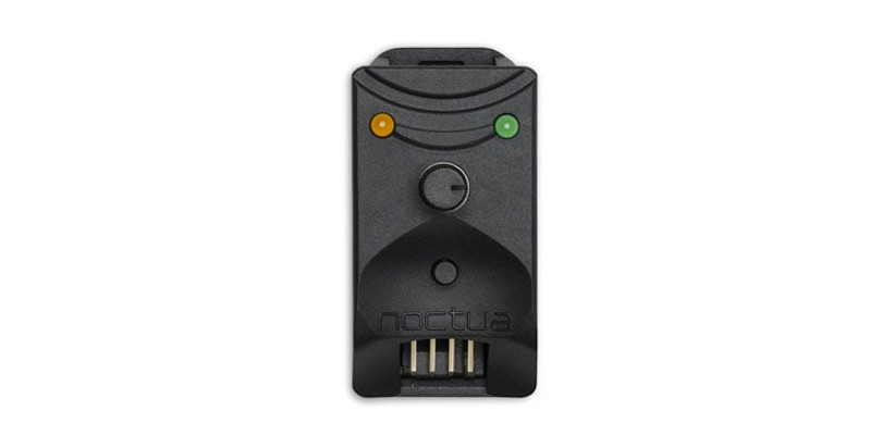
Overview of the device and accessories

- Speed control dial: Sets PWM duty cycle between 0 and 100% in manual mode or adjusts input signal from 100 to 0% in motherboard control mode (see modes of use).
- Speed setting status LED (orange): Changes in brightness according to the setting of the speed control dial (max. brightness = max. speed, min. brightness = min. speed).
- “No stop” mode push button: Press to enable/disable “no stop” mode (see “no stop” mode).
- “No stop” mode status LED (green): On in “no stop” mode, off in normal mode.
- Input connector: Connected to the motherboard or other power source using the supplied NA-EC1 cable.
- Output connector: Connected to the fan or multiple fans if splitter cables are used.
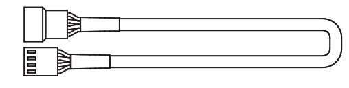
- NA-EC1 input cable: Connects the device to the motherboard or other power source.

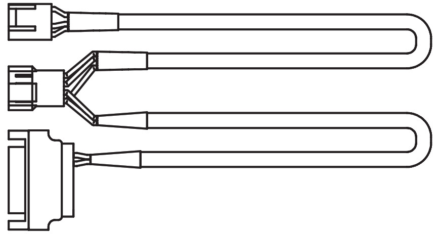
- NA-AC4 input cable with power supply adaptor: Connects the device to the power supply (S-ATA connector) and the motherboard (obtaining PWM input from the motherboard and forwarding RPM speed information to the motherboard).
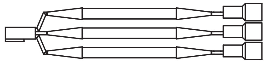
- NA-SC1 3-way splitter cable: Connects up to three fans to the output connector.
Setup
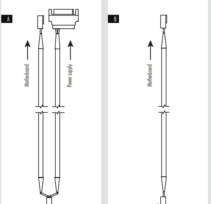
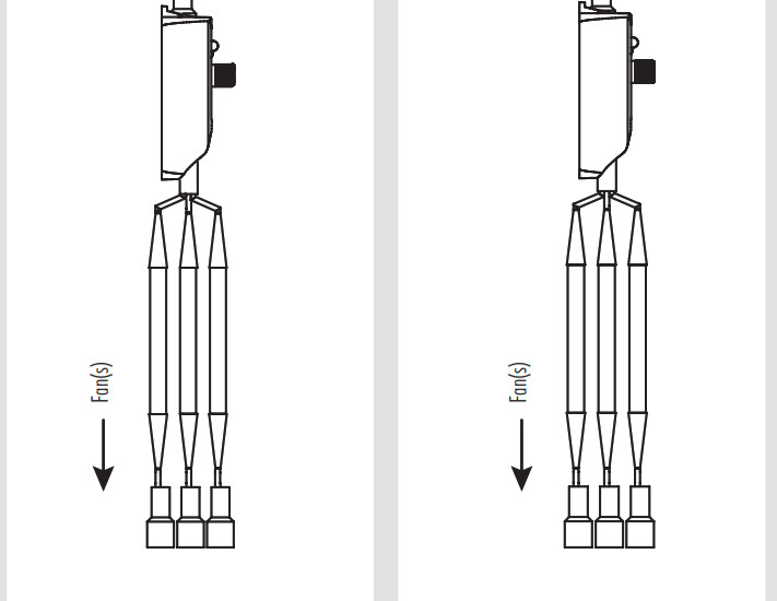
A NA-AC4 input cable with power supply adaptor 8Plug the S-ATA connector of the NA-AC4 8 to one of the S-ATA connectors of your power supply.Plug the female 4-pin connector of the NA-AC4 to the motherboard fan header and the male 4-pin connector to the NA-FC1’s input connector 5. Then connect the fan to the output connector 6. If you want to control multiple fans, first connect the NA-SC1 splitter cable 9 to the output connector and the fans to the NA-SC1.
B NA-EC1 input cable 9Caution: Please bear in mind that common motherboard fan headers usually only support up to 9.6 or 12W (check your motherboard manual for detailed information). Exceeding this rating may permanently damage your motherboard and Noctua cannot be held responsible for any such damage. Please always use the supplied NA-AC4 adaptor (see setup option A) if the combined power draw of the connected fan(s) exceeds the max. power rating of the motherboard fan header.
Connect the NA-EC1 input cable 7 to the input connector 5 and to the motherboard fan header or other power sources. Then connect the fan to the output connector 6. If you want to control multiple fans, first connect the NA-SC1 splitter cable 9 to the output connector and the fans to the NA-SC1.
Modes of use
a) Manual controlIf the NA-FC1 receives no PWM signal on the input side (from the motherboard), it will act as a manual speed controller. The NA-FC1 will then generate a PWM signal between 0 and 100% PWM duty cycle depending on the setting of the speed control dial 1. Turn the speed control dial clockwise to increase speed and anticlockwise to reduce speed. The orange speed setting status LED 2 will change in brightness according to the speed setting.
Note that the NA-FC1 can be used in manual mode when powered both from motherboard fan headers or from other power sources. It just depends on whether there is an input PWM signal or not, so simply deactivate automatic fan control in the BIOS of your motherboard if you would like to use the NA-FC1 in manual mode.
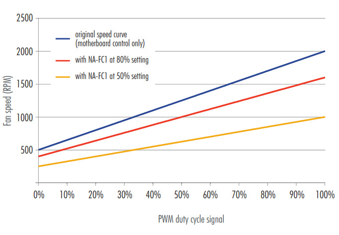
b) Adjusting automatic motherboard fan controlIf the NA-FC1 receives an input PWM signal, it will adjust the incoming signal between 100% and 0%, depending on the setting of the speed control dial . For example, if the dial is set to 50% and the motherboard provides a 100% PWM duty cycle signal, the NA-FC1 will reduce the signal by 50%, thus giving an output PWM duty cycle of 50%. If the motherboard provides 80% and the NA-FC1 is set to 50%, it will put out 40% etc. This way, the NA-FC1 will work in tandem with the motherboard’s automatic fan control, allowing you to lower the original control curve in order to achieve lower fan speeds and noise levels:
Turn the speed control dial clockwise to increase speed and anticlockwise to reduce speed. The orange speed setting status LED 2 will change in brightness according to the speed setting.
“No stop” mode
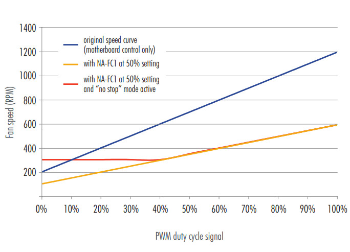
Regardless of whether the NA-FC1 works as a manual controller or adjusts an incoming PWM duty cycle signal from the motherboard, turning the speed control dial to a very low setting (or using low-speed fans) may result in very low fan speed or the fan stopping altogether. If you would like to prevent the fan from stopping, press the “no stop” mode push button 3 in order to activate “no stop” mode. In “no stop” mode (indicated by the green “no stop” mode status LED 4 being on), the NA-FC1 will not allow the fan to fall below a minimum fan speed of 300rpm, regardless of how low the speed control dial setting or incoming PWM duty cycle signal is:
“No stop” mode can be used in order to avoid motherboard fan errors that can occur below certain speed levels or if the fan stops. To exit “no stop” mode, press the “no stop” mode push button 3 again, so that the green “no stop” mode status LED 4 goes off.
Please note that many PWM fans have a minimum speed higher than 300rpm and as the function of “no stop” mode is to not let fans go below 300rpm, it is only useful for fans which are generally able to go below this speed. For example, a fan with 500rpm minimum speed will act the same with “no stop” mode on and off.
Additional notes
PWM duty cycle and fan speedResponse to PWM input can vary from fan to fan and is not always linear, so for example some 2000rpm fans may run at 1000rpm at 50% PWM duty cycle while others may run at 1200rpm. The NA-FC1 can only set a specific duty cycle, not a specific fan speed. If you would like to set a specific fan speed, please either use hardware monitoring software provided by the motherboard manufacturer or 3 rd -party tools like SpeedFan in order to check actual fan speeds during setup.
Minimum speeds and behaviour below 20% duty cycleNote that some PWM fans will stop at duty cycles below 20% while others will keep running at the same speed as they have at 20%. Also, the minimum speed achieved at 20% varies from fan to fan. As this is determined by the fan’s motor and internal electronics, the NA-FC1 cannot make fans go slower or stop, which are designed not to go below their 20% speed and/or have a high minimum speed setting. Please refer to the fan specifications for the minimum PWM speed. If you want to prevent the fan from stopping, please use the “no stop” mode.
Changing fansWhen changing fans, please briefly disconnect the NA-FC1 from the power source first in order to make sure that the cache is cleared and the new fan can be tracked correctly.
Lags when switching into “no stop” mode at low speedsPlease note that it may take up to 30 seconds until the fan is brought up to 300rpm when switching into “no stop” mode at low-speed settings.
References
[xyz-ips snippet=”download-snippet”]