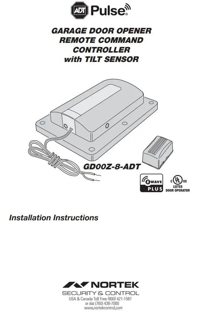
NORTEX Garage Door Opener with Tilt Sensor
GD00Z-8-ADT Installation Guide
Regulatory Information
- Z-Wave® is a registered trademark of Sigma Designs Inc. and/or its subsidiaries.
- Changes or modifications not expressly approved by the manufacturer could void the user’s authority to operate the equipment.
- This device complies with FCC Part 15 and Canada Rules and Regulations. Operation is subject to the following two conditions: (1) This device may not cause harmful interference and (2) this device must accept any interference received, including interference that may cause undesired operation.
NOTICE TO USERS IN CALIFORNIA – CR COIN CELL LITHIUM BATTERY INFORMATION: THIS PRODUCT CONTAINS A CR COIN CELL LITHIUM BATTERY WHICH CONTAINS PERCHLORATE MATERIAL – SPECIAL HANDLING MAY APPLY – SEE www.dtsc.ca.gov/hazardouswaste/perchlorate
KEEP AWAY FROM SMALL CHILDREN. IF BATTERY IS SWALLOWED, PROMPTLY SEE A DOCTOR. DO NOT TRY TO RECHARGE THIS BATTERY. DISPOSAL OF USED BATTERIES MUST BE MADE IN ACCORDANCE WITH THE WASTE RECOVERY AND RECYCLING REGULATIONS IN YOUR AREA.
Product Description
Overview
- This is a Security enabled Z-Wave product and must be used with a Security enabled Z-Wave controller in order to fully utilize this product. As such, this device will not respond to Basic CC commands.
- The GD00Z-8-ADT is a garage door opener remote command transceiver with built-in Z-Wave® technology.
- Allows remote operation of a garage door opener using the ADT Pulse touch screen, web portal, or mobile app.
- Z-Wave is an Interoperable two-way RF mesh networking technology designed for use with a Z-Wave gateway/controller and other Z-Wave enabled devices from different manufacturers.
- Acts as a Z-Wave repeater to improve communications within the Z-Wave mesh network.
- ASSOCIATION: The GD00Z-8-ADT supports 1 Group with 1 Node. Group 1 must be assigned the Node ID of the controller to which unsolicited notifications from the Controller will be sent. The ADT Pulse should set this association automatically after inclusion.
- NOTIFICATION: The GD00Z-8-ADT supports the following notification types and events: Access Control (Type 0x06) with events 0x44 (HW failure), 0x45 (UL Lockout), 0x46 (Obstruction), 0x49 (Loss of Tilt Sensor) and 0x4A (Sensor Low Battery). And additional type, Home Security (0x07) is also supported with event 0x03 (Tilt Sensor Tampered).
- Security 2 DSK label can be found on the bottom side of the product.
Summary of Operation
- Controller connects to the garage door opener’s pushbutton wall console terminals.
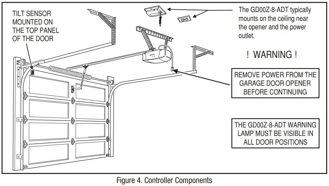
- A wireless tilt sensor mounts on the garage door and reports the door’s position to the Controller.
- GD00Z-8-ADT responds to Z-Wave commands from ADT Pulse to open or close the garage door.
- A warning indicator light flashes and a beeper sounds for 5 seconds before the door begins to move.
- If the door does not completely open or close, a second open or close command can be sent after 30 seconds.
- If the door does not completely open or close after the second attempt, the Controller operation is suspended until a local garage door pushbutton is activated.
Package Contents
The Garage Controller System
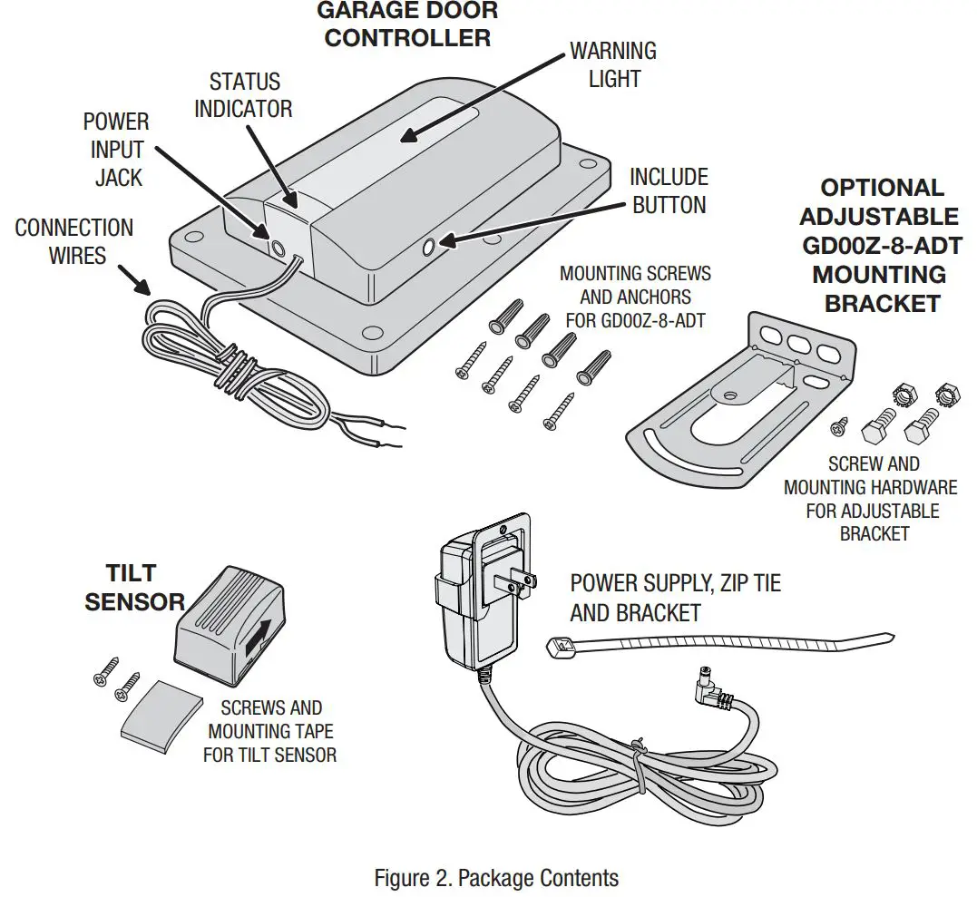
The GD00Z-8-ADT System consists of three major components:
- The Controller — The Controller wires to the garage door opener’s pushbutton terminals, receives door status from the tilt sensor, and communicates with the ADT Pulse system.
- The Tilt Sensor — The battery powered Tilt Sensor monitors the position of the garage door and sends the status to the Controller.
- The Power Supply — The Power Supply provides low voltage power to the Controller.
Tilt Sensor Installation
Mounting the Tilt Sensor
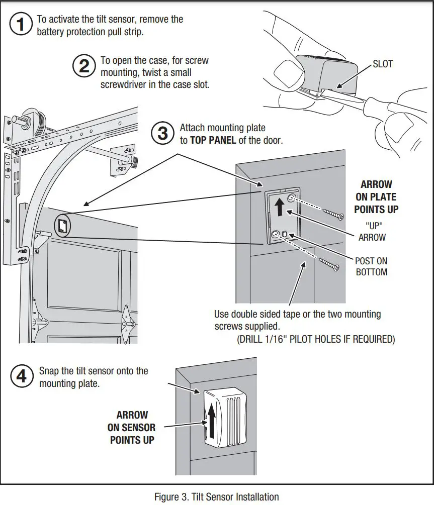
The battery powered Tilt Sensor attaches to the top panel of the garage door.
- Before installation, activate the Tilt Sensor by pulling and removing the battery protection strip.
- If using screws to mount the Tilt Sensor, open the sensor case with a small screwdriver.
- Use the double-sided tape or screws supplied to attach the Tilt Sensor to the top panel of the garage door.✓ NOTE: Drill two 1/16″ pilot holes if using the screws to attach the mounting plate.
- If the plate was removed for screw mounting, snap the Tilt Sensor on to the mounting plate.✓ NOTE: Be sure the arrow on the side of the Tilt Sensor points UP.
Enrolling with the System
Enrolling the Garage Door Controller
Before the system can be used, the ADT Pulse system needs to enroll the Garage Door Controller. Bring the Controller near your ADT Pulse Gateway and apply power to the Garage Door Controller.✓ NOTE: Before enrolling device to any Z-Wave network, or after removing it from any Z-Wave network, it is recommended that the Controller be factory reset. Reset the Controller by pressing the Include button 5 times.(Location of Include button is shown in Figure 2 on Page 3). A quick beep followed by a longer beep will indicate proper reset of the GD00Z-8-ADT.
To add a Garage Door Controller:
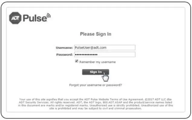
- Open your Web browser and in the address bar enter:https://portal.adtpulse.com
- Enter your Username and Password, then click the Sign In button.

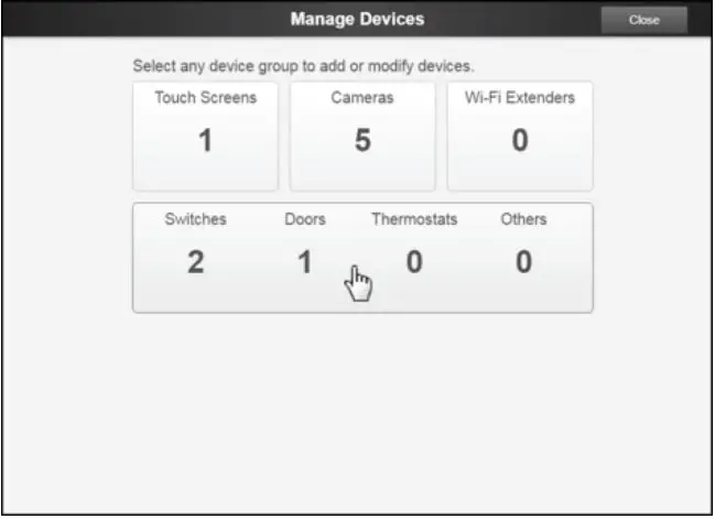
- In the Pulse portal, select the System tab, then click the Manage Devices button. The Manage Devices window opens.
- In the Manage Devices window, click Switches/Doors/Thermostats/Others. The Z-Wave Devices screen is displayed.
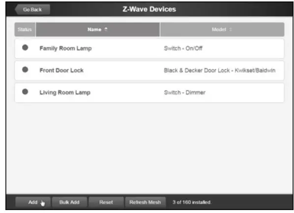
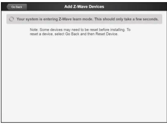
- At the bottom left of the Z-Wave Devices screen, click Add. The Add Z-Wave Devices screen is displayed.
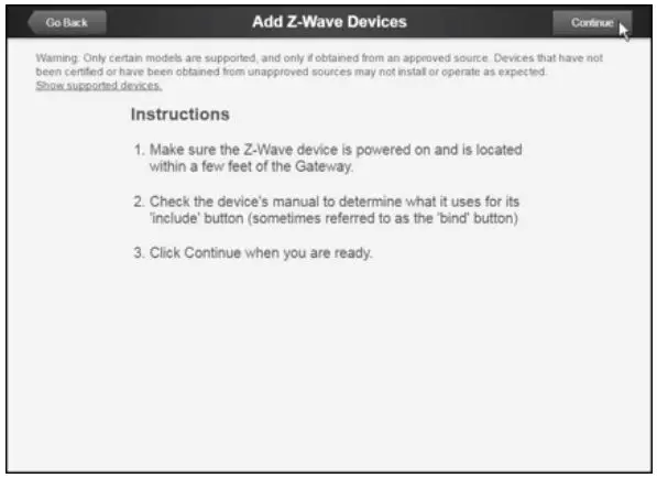
- On the Add Z-Wave Devices screen, click Continue.
- Press and hold the Garage Door Controller’s include button for 1 second (See page 3, Figure 2 for the location of the include button).
- Wait while the system finds the GD00Z-8-ADT Device.✓ NOTE: Adding the Garage Door Controller can take one to three minutes. A successful inclusion is also indicated by three short audible beeps.
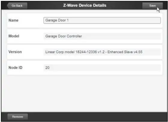
- When the device is successfully recognized, the Z-Wave Device Details screen opens. Enter a name for the device, and then click Save at the upper right.
- Click Go Back, and then Close the exit Manage Devices.
- Click Close again to confirm.
Resetting or Excluding the Garage Door Controller
If you have trouble adding the Garage Door Controller you can reset the device. Resetting the device removes it from a site (Not the same as factory resetting the device). You can then try to add the device again.
To reset a Garage Door Controller:
- In the web portal, click the System tab.
- Click Manage Devices.♦ The Manage Devices window opens..
- Click Switches/Doors/Thermostats /Others.♦ The Z-Wave Devices screen is displayed..
- At the bottom of the screen, click Reset.
- Press and release the Garage Door Controller’s include button for (1) one second.♦ The Z-Wave device resets and a two second long audible beep can be heard.♦ Click Go Back, and then Close to exit Manage Devices.
- Click Close again to confirm.
To remove a Garage Door Controller:
- In the web portal, click the System tab.
- Click Manage Devices.♦ The Manage Devices window opens.
- Click Switches/Doors/Thermostats/Others.♦ The Z-Wave Devices screen is displayed.
- Click the name of the device you want to delete.♦ The Z-Wave device Details screen displays information about the selected device.
- Click Remove at the bottom left of the screen.♦ A pop-up window prompts you to confirm.
- Click Remove to complete the deletion.✓ NOTE: If you attempt to delete a device that is referenced in an automation, alert, or schedule, or replace the device in all automations, alerts, and schedules in which it is referenced before you can delete the device. Click OK to exit without deleting the device.
Controller Mounting
Mounting the Controller in the Garage
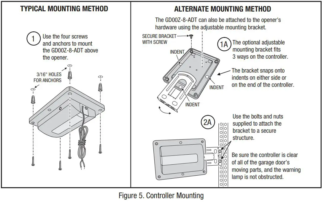
The Garage Door Controller mounts in the garage near the garage door opener. It will need to be near a power outlet and where its warning lamp can be seen, regardless of the door position. Un-plug the garage door opener before continuing.The Garage Door Controller can be screw mounted directly, or by using the supplied adjustable mounting bracket.
- Use the four anchors and screws to directly mount the Controller (use a 3/16″ drill for the screw anchors, if the anchors are used).– OR –1. Snap the adjustable mounting bracket onto the Controller and secure it with the short screw.
- Use the bolts and nuts supplied to attach the mounting bracket to available hardware.
Controller Connections
Wiring the Controller to the Opener
The Garage Door Controller wires to the garage door opener with a two wire connection.
1. Connect the GD00Z-8-ADT connection wires to the two pushbutton terminals on the garage door opener. The terminals on various models may have different names. Either wire can connect to either terminal.✓ IMPORTANT! Be sure the wires clear all moving parts of the door and opener.
Connecting the Power Supply
2. Plug the Power Supply’s cord into the jack on the Garage Door Controller.3. Join the Power Supply with the Adapter.4. Remove the outlet faceplate screw. Plug the Power Supply and bracket into a 115 VAC outlet. Align the bracket hole to the outlet hole and secure. Be sure the outlet is powered at all times and not controlled by a switch. Secure the bracket with the provided zip tie strap.✓ IMPORTANT! Do not disconnect any wires currently connected to the Garage Door Opener.
System Operation
Opening and Closing the Garage Door
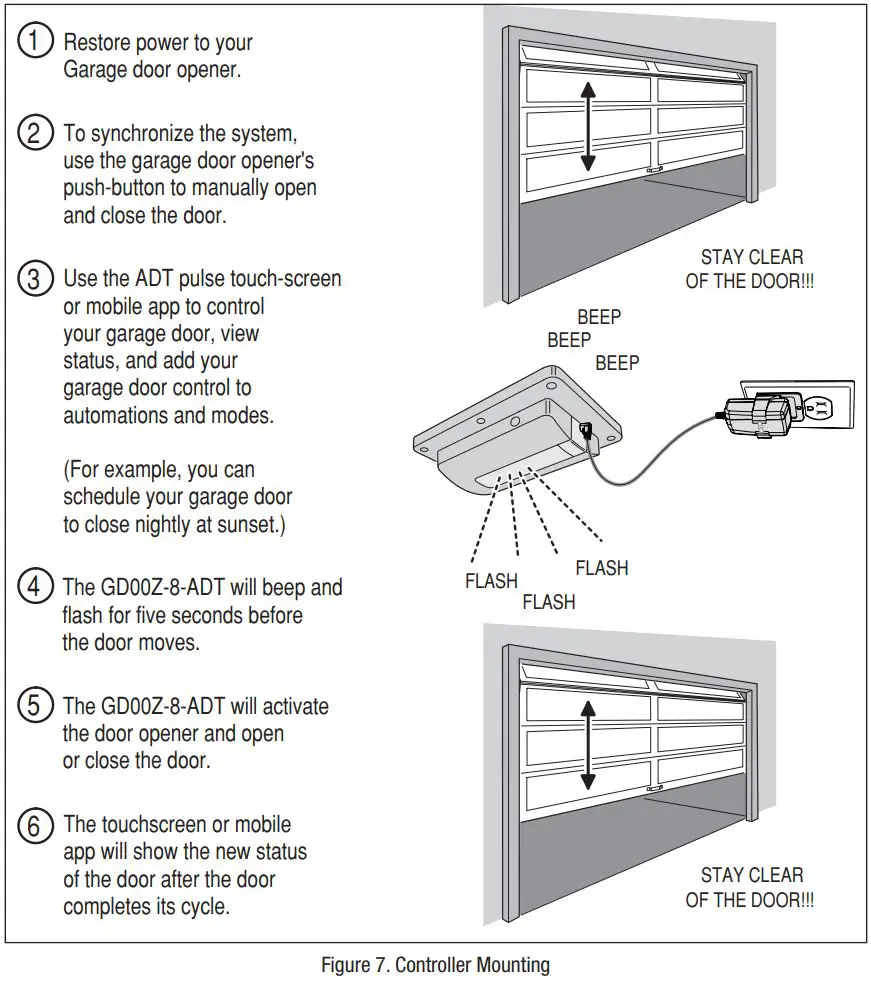
After the installation is complete, the garage door opener can be activated by the ADT Pulse system and the door’s status can be viewed through the system.
- Restore power to the garage door opener.
- Cycle the door open and closed using the wall pushbutton to synchronize the system.
- Command the ADT Pulse system to activate the garage door.
- Verify that the Garage Door Controller flashes for five seconds before the door moves.
- The door should open or close.
- Verify that the ADT Pulse system indicates the open or closed status of the garage door.
Operation Notes
Indications and Operation Notes
- The warning light will flash and the warning beeper will sound for five seconds before the door opener is activated. STAY CLEAR OF THE DOOR, AND DOOR OPENER. THEY ARE ABOUT TO MOVE!
- If the door does not completely open or close after remote activation, the Controller will allow user to try to operate the door one more time. If the second attempt fails, the Controller will go into lock-out mode. See next paragraph.
- If the GD00Z-8-ADT is in lock-out mode and will not accept remote commands, activate the door from the pushbutton wall console.
- Once the Controller has initiated the movement of the garage door, another command cannot be sent for 30 seconds. This eliminates the chance of “bouncing” the garage door and possibly damaging the garage door opener.
Tilt Sensor Battery Replacement
When The Tilt Sensor Battery Gets Low
The system will notify you when the Tilt Sensor battery gets low and needs replacing.
- Use a small screwdriver to open the Tilt Sensor case.
- Remove the low battery and insert a fresh Type CR2032 coin cell battery. BE SURE THE PLUS SIDE IS UP.✓ IMPORTANT! Disposal of used batteries must be made in accordance with the waste recovery and recycling regulations in your area.
- Return the Tilt Sensor to the garage door top panel and snap it onto the mounting plate. BE SURE THE ARROW ON THE SIDE OF THE TILT SENSOR IS POINTING UP.

Troubleshooting
If Something is not Working
Refer to the following table for information regarding possible problems and solutions if the Garage Door Controller is not operating as expected.


 report this ad
![]()
References
[xyz-ips snippet=”download-snippet”]