N1500FT Flow Rate Indicator
N1500FT IndicatorFLOW RATE INDICATOR INSTRUCTIONS MANUAL V1.2x F
SAFETY ALERTSThe symbols below are used on the equipment and throughout this document to draw the user’s attention to important operational and safety information.
CAUTION:Read this manual carefully prior to installation and operation of the unit.
CAUTION OR DANGER: Electric shock hazard
All safety related instructions that appear in the manual must be observed to ensure personal safety and to prevent damage to either the instrument or the system. If the device is used in a manner not specified in this manual, its safety features may be impaired.
INTRODUCTIONThis flow rate indicator provides indication, totalization, retransmission, alarm and RS485 communication features (optional RTU Modbus slave). It reads most flow signals available in the market, such as pulse, magnetic pickup and 4-20 mA. The pulse input allows connecting sensors with outputs such as reed-switch, NPN, PNP and tension. Both for pulse input and 4-20 mA input, unit is selectable and a scale factor is set to turn the input signal into the unit of choice. It provides an isolated pulse output for totalized flow retransmission and a 4-20 mA output for immediate flow retransmission. Alarms are set off through 2 to 4 relays, depending on the equipment model.AC models provide a 24 Vdc / 50 mA output.
INPUTSThe flow rate indicator allows for two basic input types:· Instantaneous flow input through a 4-20 mA signal. In this case, flow totalization is obtained by integrating instantaneous flow rate.· Totalized flow input through a pulse signal. In this case, instantaneous flow rate is obtained by deriving totalized flow rate.Pulse signals may come from sensors/transmitters with NPN, PNP, dry contact (reed switch) and tension signal output, or even magnetic pickup outputs.When the input is set to 4-20 mA, you should establish on screens InLL and InKL which flow values are equivalent to 4-20 mA.When the 4-20 mA input is not used as flow input, it may be used alternatively as auxiliary input. This way it is possible to measure the pressure of a pipeline, for instance.The pulse flow input may be scaled, both for instantaneous and totalized flow rates (independently), through `K’ multiplication factors: k.1nst and k.tot.Both flow time base and unit must be defined on screen Un1t 1. To do so, there are six characters, the first five of which are used to set the unit and the last one (to the right) is used to set the time base on which the flow rate is measured. Available time bases are `s’ (seconds), `m’ (minutes), `h’ (hours) and `d’ (days).
With pulse flow input, totalization will continue even if the input rate is below the minimum rate required. Instantaneous flow rate indication will be zero whenever there is a time lapse of 10 seconds without input variation. In this case, whenever there is a totalization increase (more input pulses), the instantaneous flow value will be shown for the next 10 seconds.“K” FACTORSThe instantaneous K factor (k.1nst) and the total K factor (k.tot) allow the user to view the instantaneous and totalized flow in different units.The instantaneous K factor will be available only in case the selected flow input type is different from 4-20 mA. When the input type is 4-20 mA, the configured range limits already provide the parameters for the indication.Instantaneous flow is directly related to the time base set in parameter Un1t1.In case user erroneously configures parameters k.1nSt and k.tot with value “0” (zero), this will be assigned value “0.00001”.Example 1:Chosen meter gives us an information of (pulses per volume) 50 pulses per liter. User wants to view the instantaneous flow in liters (l) and the totalized flow in cubic meters (m³).In order to do that, parameter k.1nst should be set a value of “50”, so indicating the instantaneous flow in liters. Parameter k.tot should be set a value of “50000”, so indicating the totalized flow in m³.Instantaneous flow will be viewed based on the selected time base in Un1t1. In case the example meter output is 50 pulses per second, which means 1 liter/second, and the selected time base is m (minute), the instantaneous flow indication will be 60 (liters/minute).Example 2:Chosen sensor gives us an information in 4-20 mA that corresponds to a flow between 0 and 100 liters per minute. User wants to view the totalized flow in cubic meters (m³).On this case, parameter 1N.TYPE sholud be selected as 4-20 mA and parameters InLL and InKL should be configured as “0” and “100”. This way, we pass to the equipment the information that 4 mA relates to 0 liters per minute and 20 mA relates to 100 liters per minute. In case sensor output is 12 mA, flow will be displayed as 50 liters/minute.Parameter k.tot should have a value of 0.001 (1 liter = 0.001 m³). This way, the totalized flow will be converted and displayed in m³ (cubic meters).When the instantaneous flow type is selected as 4-20 mA, the time base selected in Un1t1 have no influence over the indicated values, having just unit display purposes. The indication conversion from “liters per minute” to “liters per hour” should be adjusted directly on input limits InLL and InKL.In case user wanted instantaneous flow indicated in cubic meters per hour (m³/h) with the same meter, the values “0” and “6” should have been selected in input limits InLL and InKL, where the second value means 100 l/min converted to m³/h. k.tot parameter should be changed to “1” because input is already in m³.
NOVUS AUTOMATION
1/9
CUSTOMIZED LINEARIZATIONWhen the flow rate is read through a 4-20 mA input, it is possible to apply a customized linearization composed of 30 input points and 30 output points. Whenever the reading falls between two input points, it will be normalized to the range defined by the respective points in the output range.The input range considered as an input to the linearization table is the range defined by the user in the InLL and InKL parameters (it is not the current in mA). In case user wants to enter the values directly in mA to convert to the desired viewing unit, parameter 1n LL must be set as 4 (mA) and parameter 1n xl as 20 (mA), using as many decimal places as needed to the desired precision. It will be possible then to enter values between 4-20 (mA) as input points for the customized linearization.The search for framing the value read is done while the list of input points is incrementally declared. The search is terminated if the next point in the list is lower than the current one. If the input value is lower than the first value in the list of input points, linearization will return the first output value. Similarly, if the input value is greater than the highest value in the list of input points, linearization will return the highest value in the output list.IMPORTANT: At least two pairs of input-output points are required for adequate customized linearization.RETRANSMISSIONFlow rate retransmission can be done via 4-20 mA output and pulse output.The 4-20 mA output may be used regardless of the type of flow input. To use it, just set the retransmission range to RTLL and RTKL, associating the flow rates to 4-20 mA.In the case of retransmission via pulse output, one must choose between volumetric pulse output and frequency pulse output. The former may be used regardless of the type of input, while the latter is available only for pulse inputs.In the volumetric mode, a pulse of configurable length is generated every time the totalizer accumulates a preset volume. For example, for a period of 1 second and volume of 10 liters, a 1-second pulse will be generated for every 10 liters totalized. The counting to the output pulse will be reset every time the user resets the totalizer or whenever a feeding process is finished.Note: In case the feeding process is running and the totalizer is reset by the user, the process will remain running normally, but the output pulse will not be synchronized with this process anymore, which can lead to a missing pulse informed at the end of the feeding process. As it is always reset at the end of the process, output pulse counter will synchronize again for a new feeding process.In the frequency mode, the pulse output will divide the input frequency by a programmable constant whose value is equal to or higher than 2.IMPORTANT: Maximum output frequency has hardware limitation. See Specifications. Check the “Specifications”.ALARMSThe indicator’s basic version has 2 alarm outputs, with the option of up to 4 alarms. Whenever an alarm is on, a corresponding light signal will be displayed on the front panel.ALARM FUNCTIONSThe alarms can be programmed to operate with four different functions, described below. They may also be turned off.Alarms use only the instantaneous flow rate reading. Totalization readings cannot be used as input for alarms. The auxiliary 4-20 mA input (when it is not being used for flow rate measurement) may be used only as input for the open sensor alarm.· Open Sensor I.errorThe open sensor alarm operates whenever the input sensor is badly connected or broken. Valid only for 4-20 mA inputs.NOVUS AUTOMATION
N1500FT Flow Indicator
· Minimum Value LoIt sets off when the reading is below the value determined by the alarm Setpoint.
· Maximum Value KiIt sets off when the reading is above the value determined by the alarm Setpoint.
· Feeder Function FEEDER
It activates the output relay when it is started by pressing
or
via the auxiliary digital input (according to setup) and deactivates
when the reading reaches the value determined by the alarm setpoint
or when the
key or digital input is pressed/closed again,
putting the process on hold. In case of pressing the
key or
digital input more than 3 seconds, process is reset and stays waiting
to be started.
Further details in the “Feeder” section.
ALARM TIMERThe indicator allows setting up an Alarm Timer, where users can set the alarm to go off with a delay, to go off in only one pulse or to go off in sequential pulses.Figures in Table 1 show these functions. There, times T1 and T2 may vary from 0 to 32000 seconds and are defined while programming the indicator. For regular (no timers) operation of alarms, simply set T1 and T2 to 0 (zero).He alarm light signals will be displayed whenever there is alarm condition, regardless of the current status of the output relay, which may be temporarily out of power because of the timer function.
ADVANCED FUNCTION
T1
T2
ACTION
Regular Operation
0
Alarm
0
Output
Alarm Event
Delay
Alarm
0
1 to 32000 Output
T2
Alarm Event
Pulse 1 to 32000 0
Alarm
Output
T1
Alarm Event
Alarm
Oscillator 1 to 32000 1 to 32000 Output
T1
T2
T1
Alarm Event
Table 1 – Alarm timer functions
ALARM HYSTERESISHysteresis defines the difference between the value measured when the alarm is triggered and the value at which it is deactivated.
INITIAL ALARM BLOCKThe initial block option prevents the alarm from going off in case there is alarm condition at the time the indicator is being energized. The alarm may be triggered only after a non-alarm condition is followed by an alarm condition. This function is not valid for alarms programmed as Open Sensor.
SPECIAL FUNCTIONS
MAXIMUM AND MINIMUM
The flow indicator continuously records the minimum and maximum
values of instantaneous flow rate. These values can be viewed on
the first screen of the main cycle by pushing
and
,
respectively. The
key can be set to zero maximum and
minimum values.
2/9
AUXILIARY DIGITAL INPUT AND
KEY
Similarly to a digital input, the
key can be set to zero the
totalizer, freeze the main screen, zero minimum and maximum
readings or control the feeder function.
FEEDER
The feeder function is used to control the volume of fluids based on its flow rate. It is typically used for storage applications, where there is a start signal that triggers a relay and the flow rate begins to be measured. When reaching a given setpoint, this relay is deactivated to stop flow.
Its use depends on correct configuration of the related alarm.
During the feeder process, it is not possible to change the alarm
setpoint. Process should be reset first to allow it.
Functions of
key and/or digital input, when assigned to the
feeder function:
· When the
key or digital input is activated, the feeder
process is started, activating all relays related to the feeder alarm;
· In case the
key or digital input is activated once again, the
process is frozen and all relays related to the feeder alarm are
deactivated;
· To restart the feeder process,
key or digital input must be
activated for 3 seconds, until the process is restarted, zeroing all
existing feeder indication. This can be done with the process
stopped or running;
· At the end of the feeder process, when alarm setpoint is reached,
process values are frozen and all related relays are deactivated.
To restart a new process, just activate the
key or digital
input for all counters to be reset and process will start running;
· In case of a power shortage, if the feeder batch reset parameter (Bat.rst) is configured as no, whenever the equipment powers up again the process will restore from where it stopped. This means that, if it was in the middle of a feeder process, all relays assigned to the feeder alarm will be activated. If the process was stopped, all counters will keep their values and the process will remain stopped until it is activated either by thekey or the digital input.
MANUAL OPERATION MODEIn the hardware cycle, outputs can be set manually. This can be extremely useful for tests and simulations. After exiting the cycle, outputs go back to their regular status.
24 VDC AUXILIARY POWER SUPPLY DC power supply models provide a 24 Vdc output for field transmitters.
INSTALLATIONThe indicator must be installed on a panel. To do so, remove the two plastic clamps, introduce the device in the panel cutout and put the clamps back from the rear side of the indicator.
INSTALLATION RECOMMENDATIONS· Input signal conductors should be disposed in the system separately from output conductors and power conductors, preferably in grounded electrodes.· Instruments should be powered through a dedicated network.· For control and monitoring applications it is vital to consider what might happen if any part of the system fails. The alarm internal relay does not ensure total protection.· It is recommended to use RC FILTERS (47 and 100 nF, series) in contactor coils, solenoid coils, etc.
N1500FT Flow IndicatorELECTRICAL CONNECTIONS All the inside can be removed without the need to undo the electrical connections. Disposition of signals in the rear panel of the indicator is shown in Fig. 1.
Fig. 1 Rear panel connections POWER SUPPLY CONNECTION
Fig. 2 Power supply terminalsCONNECTIONS FOR INPUT AND OUTPUT SIGNALS It is important that these connections are well made, with signal or sensor wires securely attached to rear panel terminals. Check the “Specifications” section for the range of the input signals.The images below show connections for different input types:
Fig. 3 Auxiliary digital input connection
Fig. 4 – Flow pulse input Voltage signals
Fig. 5 – Flow pulse input NPN signals
Fig. 6 – Flow pulse input PNP signals
Fig. 7 – Flow pulse input Dry Fig. 8 Coil Signal connection
contact signals
(magnetic pickup)
NOVUS AUTOMATION
3/9
The images below show connections for different output types:
Fig. 9 – Current connection
Fig. 10 Pulse output connection
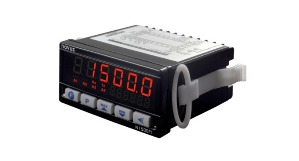
Fig. 11 – 24 V auxiliary power supply connectionOPERATIONThe indicator front panel, and its parts, can be viewed in Fig. 12:
Fig. 12 Identification of front panel parts
The indicator has the following parts:Upper Display / Programming: Shows the intended value (set on Ma1n screen of Function Cycle). At the time of setup, it shows the mnemonics for the different parameters that should be defined.Lower Display / Parameters: Shows the intended value (set on Ma1n screen of Function Cycle). At the time of setup, it shows the values established for the several parameters.Rx and Tx Indicators: They show activity in the RS485 communication line.A1, A2, A3 and A4 Indicators: They show the alarms that are on.
Key: “Function” key, whose operation is user selectable.
Key: This key has two functions. When you press it quickly, you are taken to the next screen. When you press and hold for more than 3 seconds, you will be taken to the next cycle and subsequently on if you keep holding.
Up
and Down
keys: They allow changing the parameter
values. They are also used for viewing the memorized maximum and
minimum values.
Key: Return key. When you press it quickly, you are taken to the previous screen. If you press and hold for more than 3 seconds outside the main cycle, you will be taken back to the main cycle. If you hold this key for more than 10 seconds inside the main cycle, the 8-digit serial number will be shown on both displays.
FUNCTION
OPERATION METHOD
Go to the next cycle.
Press seconds.
for more than 3
Go to next screen in the cycle.
Press
.
Go to previous screen in the cycle.
Press
.
Increase the number of decimal places in the value viewed.
Press
while holding
.
Available only for some parameters!
Reduce the number of decimal places in the value viewed.
Press
while holding
.
Available only for some parameters!
N1500FT Flow Indicator
Change a digit in the value being modified.Change a parameter.Show the maximum value. Show the minimum value. Show the equipment serial number.
Press
while holding
.
Available only for some parameters!
Press
or
to select the
next option or, in the case of a
numerical value, to increase or
decrease the value.
On the first screen of the main cycle, press .
On the first screen of the main cycle, press .
On the first screen of the main cycle,
press
for 10 seconds.
SPECIAL KEYBOARD FUNCTIONS (DECIMAL PLACES)
There are several screens whose values are the “floating point” type, that is, they take a varying number of decimal places. In such cases, special combinations of keys may be used to edit values.
The special function is activated by pressing
, therefore you
have 3 seconds to use it with any other key, otherwise the original
.
In order to increase the number of decimal places, quickly press
while holding
. The number of decimal places will be
reduced if you quickly press
while holding .
When the operating element of the screen is the floating point type, it
is also possible to choose which digit will be increased or decreased.
In order to choose the digit, quickly press
while holding .
Selection of the digit occurs from right to left and the chosen digit will
blink fast.
There is an exception to the main screen. Instead of parameters, this
screen shows values for the inputs. These values are shown as
floating points in both displays. In this case, it is possible to set the
number of decimal places in the lower display by quickly pressing
while holding
. In order to set the number of decimal
places in the upper display, quickly press
while holding .
Note: It is recommended to disable/suspend the control whenever it is necessary to change the device settings.
PROGRAMMING THE INDICATOR
MAIN CYCLE
888888 888888SP.A1Setpoint Alarm 1SP.A2Setpoint Alarm 2SP.A3Setpoint Alarm 3SP.A4Setpoint Alarm 4
The first screen of the main cycle can be programmed in the Main screen. Setpoint Alarm 1. Visible only is alarm 1 is active.Setpoint Alarm 2. Visible only is alarm 2 is active.Setpoint Alarm 3. Visible only is alarm 3 is active.Setpoint Alarm 4. Visible only is alarm 4 is active.
Table 2 Main cycle keys
NOVUS AUTOMATION
4/9
ALARM CYCLE
Fva1Function Alarm 1xya1Hysteresis Alarm 1BLA1Block Alarm 1A1t1Alarm 1 Timer 1A1t2Alarm 1 Timer 2Fva2Function Alarm 2xya2Hysteresis Alarm 2BLA2Block Alarm 2A2t1Alarm 2 Timer 1A2t2Alarm 2 Timer 2Fva3Function Alarm 3Xya3Hysteresis Alarm 3BLA3Block Alarm 3A3t1Alarm 3 Timer 1A3t2Alarm 3 Timer 2Fva4Function Alarm 4xya4Hysteresis Alarm 4BLA4Block Alarm 4A4t1Alarm 4 Timer 1A4t2Alarm 4 Timer 2
Selection of Alarm 1 function: off, 1.Error, Lo, x1 and FEEDER.
Hysteresis Alarm 1. Block Alarm 1.
Visible only if Fva1 is different fromoff, from 1.Error and Feeder.
Alarm 1 Timer 1 (in seconds).Alarm 1 Timer 2 (in seconds).
Visible only if Fva1 is different from off and Feeder.
Selection of Alarm 2 function: off, 1.Error, Lo, x1 e FEEDER.
Similar to Alarm 1.
Visible only if Fva2 is different from off, from 1.Error and Feeder.Visible only if Fva2 is different from off and Feeder.
Selection of Function Alarm 3: off, 1.Error, Lo, x1 and FEEDER.Visible only for the 4 relays model.
Similar to Alarm 1
Visible only if Fva3 is different from off, from 1.Error and Feeder.Visible only if Fva3 is different from off and Feeder.
Selection of Function Alarm 4: off, 1.Error, Lo, x1 and FEEDER.Visible only for the 4 relays model.
Similar to Alarm 1
Visible only if Fva4 is different from off, from 1.Error and Feeder.Visible only if Fva4 is different from off and Feeder.
Table 3 Alarm cycle keys
NOVUS AUTOMATION
N1500FT Flow Indicator
FUNCTION CYCLE
Ma1nMain screen ProgKey fKey Functiond.1n FDigital Input FunctionresetResetBat.rst Feeder BatchResetbavdBaud rateParityParityADDRAddress
Setup of first screen of the main cycle. See Table 5.
Selection of See Table 6.
key function.
Selection of digital input function. See Table 6.
Resets totalizer.When the no option is selected: In case of a power loss, feeder process states and variables will not be lost and, whenever power is back, it will resume feeding automatically, just as it was before the power loss. When the yes option is selected: In case of a power loss, feeder process states and variables will be reset and, whenever power is back, it will remain waiting for a new process start.Serial communication baud rate.
Serial communication parity.
Serial communication address.
Table 4 Function cycle keys
Table 5 shows the available options for the main screen.
UPPER DISPLAY
LOWER DISPLAY
Scrn 1 Scrn 2Scrn 3
Instantaneous flow rate Totalized FlowInstantaneous flow rate
Totalized FlowInstantaneous flow rateNon-resettable Totalized Flow
Scrn 4
Non-resettable Totalized Flow
Instantaneous flow rate
Scrn 5 Scrn 6Scrn 7
Instantaneous flow rate Unit
Totalized Flow
Unit
Non-resettable Totalized Flow
Unit
Scrn 8 Varies between Scrn 5 and Scrn 6
Scrn 9 Varies between Scrn 5 and Scrn 7
Scrn 10 Scrn 11Scrn 12
Instantaneous flow rateTotalized FlowNon-resettable total flow rate
Auxiliary AuxiliaryAuxiliary
Scrn 13
Feeder flow (counting forwards)
Feeder setpoint
Scrn 14
Feeder flow (counting backwards)
Feeder setpoint
Scrn 15
Instantaneous flow rate
Feeder flow (counting forwards)
Scrn 16
Instantaneous flow rate
Feeder flow (counting backwards)
Scrn 17 Totalized Flow
Feeder flow (counting forwards)
Scrn 18 Totalized Flow
Feeder flow (counting backwards)
Table 5 – Main screen options
5/9
For screens that show totalizations, whether it is the total or the non-resettable value, when the reading cannot be shown in six digits it will be shown in two halves; that is, the lower six digits and the higher five digits (preceded by a k. to indicate it is the high half) will be displayed in turns every five seconds.
In case no alarm is configured as “feeder”, a “——” will be displayed.
Table 6 shows the options for digital input and the
key.
Off Rst.totkold.1n
No function.Totalization reset.Freezes display while the input is active or the key is pressed.
Rst.MM feeder IGnore
Resets minimum and maximum values.Start of Feeder function. Further details in the “Feeder” section. Suspends totalization, ignoring input signal, but keeps retransmission working.
Table 6 – Options for digital input and the
key
INPUT SETUP CYCLE
1N.TYPEInput Type1N.4-20Input 4 to 20 mA1n LLInput Low Limit1n xLInput High Limit(Ut0ffCut OffFLTR.1nFilter InputUn1t 1Unit InstantaneousUn1t tUnit totalizerk.1nstK Instantaneousk.totK totalizerS.rootSquare root
Selection of flow input type. See Table 8.Selection of 4-20 mA input as auxiliary input. Available only if flow input is different than 4-20 mA.Value for the beginning of the auxiliary input range. Available only if the 4-20 mA input is enabled.Value for the end of the auxiliary input range. Available only if the 4-20 mA input is enabled.Minimum flow rate for indication. Any flow rate below this value is shown as 0 and will not increment the totalizer.4-20 mA input filter. Available only if the 4-20 mA input is enabled.Unit for indicating instantaneous flow rate. It also establishes the time base for this measurement in Seconds, Minutes, Hour or Days (free alphanumeric description): —–s / m / h / D (Seconds / Minutes / Hour / Days)Unit for totalized flow rate indication: “——” (free alphanumeric description).K factor to be applied on the flow rate reading through the digital input. Available only if flow input is different than 420 mA. Instantaneous K factor has its value set as “pulses per volume”.K factor to be applied on total volume. When using pulse input, total K factor has its value set as “pulses per volume”. Square root. Available only if the 4-20 mA input is enabled. The “YES” option applies quadratic function on the input signal within the limits programmed in “inLL” and “inkL”.Table 7 Input setup cycle keys
NOVUS AUTOMATION
N1500FT Flow Indicator
SELECTION OF FLOW INPUT TYPE
SENSOR
DESCRIPTION
4 to 20 d.1.nPn D1.PnP Sw1tch pickvp
4-20 mA analog signal NPN or tension type digital input NPN digital input Dry Contact (reed switch) digital input Coil signal input (from 30 mVpp)
Table 8 Input sensor type
Note: For information about reading speed, check Specifications.
OUTPUT SETUP CYCLE
rtllRetransmition Low LimitrtxlRetransmition High Limit0UT.errOutput ErrorPULSePulsew.pulseVolume PulsePulse.tPulse TimefreqdwFrequence Divider
Retransmission lower limit. It is the flow rate value that corresponds to the 4-20 mA output lower limit. When rtkl is equal to rtll, output is turned off.Retransmission higher limit. It is the flow rate value that corresponds to the 4-20 mA output higher limit. When rtll is equal to rtkl, output is turned off.Value to be applied to 4-20 mA output in case of input failure.Configuration of pulse output. Options are off, volumetric pulse and frequency.Volume to be accumulated to generate an output pulse. Available only when pulse output is set to volumetric pulse.Time period during which pulse remains active after having reached intended volume. Available only when pulse output is set to volumetric pulse.Input frequency divider. Available only when pulse input is set to frequency.
Table 9 Output setup cycle keys
When pulse output is set as volumetric pulse, a pulse is generated every time the totalizer accumulates the value programmed on the w.pulse screen. For example, if u.pulse is programmed to 10, then a pulse will be generated for every 10 units of computed volume.When pulse output is set to frequency, the output signal will be an input signal divider.
RELAY CONFIGURATION CYCLE
Rl 1Relay 1Rl 2Relay 2Rl 3Relay 3Rl 4Relay 4
Relay 1 function selection: off, Al 1, al 2, al 3 e al 4.Relay 2 function selection: off, Al 1, al 2, al 3 e al 4.Relay 3 function selection: off, Al 1, al 2, al 3 e al 4.Relay 4 function selection: off, Al 1, al 2, al 3 e al 4.
Table 10 Relay configuration cycle screens
If there is need for activating more than one output relay by the same alarm, just assign the desired relays to the desired alarm. Default configuration assigns one relay to its related (same index) alarm (relay 1 for alarm 1, relay 2 for alarm 2, and so on).
6/9
CUSTOMIZED LINEARIZATION CYCLE
Lin.enblLinearization Enable1np.01Input 010vT.01Output 011np.02Input 020vT.02Output 02
Enables linearization. Applicable only when flow input is 4-20 mA. First input point for linearization. First output point for linearization. Second input point for linearization. Second output point for linearization.
…
27 input and output points for linearization.
1np.30Input 300vT.30Output 30
Last input point for linearization. Last output point for linearization.
Table 11 Customized linearization cycle keys
HARDWARE CYCLE (MANUAL MODE)
manualManual mode(ur.0utCurrent OutPUl.0utPulse OutRl1.0utRelay 1 OutRl2.0utRelay 2 OutRl3.0utRelay 3 OutRl4.0utRelay 4 Out
Enables manual mode of operation.Current output status in manual mode.Pulse output status in manual mode.Relay 1 output status in manual mode.Relay 2 output status in manual mode. Relay 3 output status in manual mode. Visible only for the 4 relays model. Relay 4 output status in manual mode. Visible only for the 4 relays model.
Table 12 Hardware cycle keys
CALIBRATION CYCLE
All input and output types are factory calibrated. If recalibration is required, it must be performed by a specialist. If this cycle is accidentally accessed, go through all parameters without changing values.
PASSPassword
Access Password entry.This parameter is shown before protected cycles. See item Configuration Protection.
(alibCalibrationinL(Input Low Calibrationinx(Input High Calibration
Enables calibration.Entry of value close to the beginning of scale in 4-20 mA input, within scale specified in InLL and InKL.Entry of value close to the end of scale in 4-20 mA input, within scale specified in InLL and InKL.
ovL(Output Low Calibration
On this screen, whenever you press
or
, a standard current close to 4 mA will
be applied. Measure current, in mA, and enter
it on this screen.
NOVUS AUTOMATION
N1500FT Flow Indicator
ovx(Output High CalibrationrstrRestorePa.(xPassword ChangeProtProtection
On this screen, whenever you press
or
, a standard current close to 20 mA will
be applied. Measure current, in mA, and enter
it on this screen.
Restores factory calibration.
Changes user password.
Protection level. Table 13 Calibration cycle keys
CONFIGURATION PROTECTIONThe indicator allows configuration protection as determined by user, preventing unauthorized changes. The Protection (PROt) parameter, in the Calibration cycle, determines the protection level to be adopted, limiting Access to cycles, as shown in the table below.
PROTECTION LEVEL
PROTECTED CYCLE
1
Calibration
2
Calibration + Hardware
3
Calibration + Hardware + Linearization
4
Calibration + Hardware + Linearization + Relays
5
Calibration + Hardware + Linearization + Relays + Output Config. + Input Config.
6
Calibration + Hardware + Linearization + Relays + Output Config. + Input Config. + Functions
Calibration + Hardware + Linearization + Relays
7
+ Output Config. + Input Config. + Functions +
Alarm
Calibration + Hardware + Linearization + Relays
8
+ Output Config. + Input Config. + Functions +
Alarm + Main
Table 14 Configuration Protection Levels
Access PasswordTo access the protected cycles, it is necessary to enter an Access Password that allows altering the configuration of parameters in these cycles.The access password is entered in the Pass parameter, which is shown in the first of protected cycles.Without a protection password, parameters of the protected cycles can be only viewed.The Access Password is defined by user in the Password Change (PA.(k) parameter, shown in the Calibration cycle.New indicators come from factory with access password “1111”.
Master PasswordIf you forget the access password, it is possible to use the Master Password feature. When this password is entered, users gain access to the Password Change (PA.(k) parameter and are allowed to specify a new access password to the indicator.The Master Password consists of the last three digits of the indicator serial number added to the number 9000.For example, for a device with serial number “12154321”, master password is “9 3 2 1”.
MAINTENANCEPROBLEMS WITH INDICATOR Connection errors and inadequate programming are the main problems when using the indicator. A final review should prevent losses and wasting time.7/9
MESSAGE VVVVVnnnnn ——
PROBLEM DESCRIPTIONValue reading is above limits allowed for this sensor or signal.Value reading is below limits allowed for this sensor or signal.Open input. No sensor or signal. Also displayed in the “feeder” screens in case no alarm is configured as “feeder”.
SPECIAL RECOMMENDATIONSShould your indicator be repaired, special care must be taken with handling. The device must be removed from the case and immediately placed in an antistatic wrap, protected from extreme heat and humidity.
CALIBRATION
Both analog input and output are factory calibrated, and recalibration should not be performed by inexperienced operators. If recalibration of a given range is necessary, proceed as follows.
INPUT CALIBRATION
1. Set input type to be calibrated to 4-20 mA;
2. Program inll (lower limit) and inkl (higher limit) indication parameters to maximum and minimum values of input type;
3. Apply to entry a signal corresponding to a known indication and close to its lower limit;
4. Enter calibration cycle with correct password;
5. Access inl( parameter. With
and
keys, have
parameter display show applied value. Then Press ;
6. Apply to entry a signal corresponding to a known indication and close to its higher limit;
7. Access ink( parameter. With
and
parameter display show applied value;
keys, have
8. Press
or
to exit screen and activate calibration.
OUTPUT CALIBRATION
1. Mount a millimeter in the analog control output;
2. Enter calibration cycle with correct password;
3. Select oUL( parameter. Use
and
keys so that the
device recognizes the process of calibration of current output.
4. Read current in the millimeter and enter it in the oUL( parameter
using
and
keys. Then press ;
5. In parameter oUx(, use
and
keys so that the device
recognizes the process of calibration of current output;
6. Read current in the millimeter and enter it in the oUx( parameter
using
and
keys;
7. Press
or
to exit screen and activate calibration.
SERIAL COMMUNICATIONThe indicator may be optionally supplied with a RS485 asynchronous serial communication interface for communicating with a supervisor computer (master). The indicator always operates as slave.Communication is always initiated by the master, which sends a request to the slave address with which it wants to communicate. The addressed slave takes control and sends a response to the master.The indicator takes broadcast type commands (addresses to all network instruments). For this type of command, the indicator does not send any reply or acknowledgement.
FEATURESSignals compatible with RS485 standard. MODBUS (RTU) Protocol. 2-wire connection between 1 master and up to 31 indicators (it is possible to address up to 247 units) in bus topology.
N1500FT Flow Indicator
Communication signals are electrically isolated from the rest of the indicator.· Maximum connection distance: 1000 meters.· Selectable speed; 8 bits of data; 1 stop bit; selectable parity (no parity, even or odd).· Start time of response transmission: 100 ms maximum after receiving the command.
ELECTRICAL CONNECTIONS: RS485 INTERFACE
RS485 signals are:
D1 D D+ B Bi-directional data line
Terminal 25
D0
D-
A
Reverse bi-directional data line
Terminal 26
C
Optional connection that
improves communication Terminal 27
GND
performance.
CONFIGURATION OF SERIAL COMMUNICATION PARAMETERS Two parameters must be configured for serial use: Baud: Communication speed. Prty: Communication parity. Addr: Communication address of indicator.REDUCED REGISTERS TABLE FOR SERIAL COMMUNICATION
Communication Protocol
Slave MODBUS RTU protocol supported. All configurable parameters of the indicator may be read and/or written through serial communication. Writing on registers in broadcast mode using the address 0 is also allowed.The following Modbus commands are available:
03 – Read Holding Register
06 – Preset Single Register
05 – Force Single Coil
16 – Preset Multiple Register
Holding Registers TableThe following are the most commonly used registers. For further information, refer to the Table of Registers for Serial Communication available for download on the flow indicator website at www.novusautomation.com.The registers below are read-only. The ones that are available in a floating point format require two registers for being 32-bit values.
Address Parameter
Register Description
0000
and
Instantaneous Instantaneous flow value in floating flow rate point (IEEE-754).
0001
0002
and
Totalized Flow
Flow totalization point (IEEE-754).
value
in
floating
0003
0004
and
Non-resettable Grand total flow value in floating point Totalized Flow (IEEE-754).
0005
0013
Flow totalization value in integer
to
Totalized Flow
format (with signal) of 64 bits. The most significant part is in the first
0016
register.
0017
Grand total flow value in integer
to
Non-resettable format (with signal) of 64 bits. The Totalized Flow most significant part is in the first
0020
register.
NOVUS AUTOMATION
8/9
SPECIFICATIONSDIMENSIONS:………………………………………48 x 96 x 92 mm (1/8 DIN) …………………………………………………….Approximate Weight: 242 gPANEL CUTOUT: ……………………………..45.5 x 93 mm (+0.5 -0.0 mm)POWER SUPPLY: ……………….. 100 to 240 Vac/dc (±10 %), 50/60 Hz Optional 24 V:………………. 12 to 24 Vdc / 24 Vac (-10 % / +20 %) Maximum Consumption: ……………………………………………. 7.5 VAENVIRONMENTAL CONDITIONS: Operation Temperature:………………………………………… 5 to 50 °C Relative Humidity: ……………………………….. 80 % max. up to 30 ºC For temperatures above 30 °C, reduce 3% by °C Internal use; Category of installation II, Degree of pollution 2; altitude < 2000 mINPUTS4-20 mA:…………………………………..Accuracy: ± 0.2 % of full scaleDry Contact: ……………………………………..Frequency: 0.1 to 10 HzPulse (Tension, NPN or PNP): ……..Frequency: 0.1 to 50000 Hz …………………………………………………… Amplitude: from 4 V to 24 V …………………………………………………Accuracy: ± 30 ppm @ 25 °CMagnetic Pickup: ……….. Frequency: 0.1 to 8000 Hz @ 30 mVpp …………………………………………………0.1 to 50000 Hz @ 250 mVpp ………………………………………….Amplitude: from 30 mVpp to 5 Vpp ……………………………………………………Accuracy: ± 0.1 % @ 25 °CInput impedance:………………… 4-20 mA: 150 (+4.5 Vdc @ 20 mA) OUTPUTS:4-20 mA:……………………………………….. 550 max., 10000 levels ………………………………………………………………..Isolation: 250 VrmsPulse: ……………………………………….. Maximum frequency: 100 Hz ……………………………………………………………… Voltage: 0 to 30 Vdc ………………………………………………………. Maximum current: 15 mA ………………………………………………………………..Isolation: 250 VrmsOUTPUT RELAYS:ALM1 and ALM2: ………………………………………………………………… ………………………….. SPDT: 3 A / 240 Vac (3 A / 30 Vdc resisitive)ALM3 and ALM4: ………………………………………………………………… ………………….. SPST-NA: 1.5 A / 250 Vac (3 A / 30 Vdc resisitive)ELECTROMAGNETIC COMPATIBILITY: …………………………………….. …………………………………..EN 61326-1:1997 and EN 61326-1/A1:1998SAFETY:……………………….EN61010-1:1993 and EN61010-1/A2:1995Connections suitable for fork-type terminals 6.3 mm.FRONTAL PANEL: ………………………… IP65, polycarbonate UL94 V-2CASE: …………………………………………………….IP20, ABS+PC UL94 V-0Operation is started: three seconds after connection to power supply.
IDENTIFICATION
N1500FT –
4R –
485 –
24V
A
B
C
D
A: Indicator model: N1500FT
B: Output relays:
Nothing shown (basic version with two SPDT relays);
4R
(version with two additional SPST relays);
C: Digital Communication:
Nothing shown (basic version with no serial communication);
485
(version with RS485 serial, Modbus protocol)
D: Power Supply:
Nothing shown (basic version, power supply of 100 to 240 Vac);
24V
(version with power supply of 12 to 24 Vdc /
24 Vac).
N1500FT Flow IndicatorWARRANTYWarranty conditions are available on our website www.novusautomation.com/warranty.
NOVUS AUTOMATION
9/9
[xyz-ips snippet=”download-snippet”]