MPG With Display NVMPG User Manual
Chapter 1. Brief Introdution
Products brief introduction
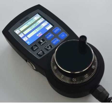
We design a new Manual Pulse Generator named NVMPG. This MPG has a screen, and 10 buttons. The coordinates and some other parameter are displayed on the screen.
And user can change axis and rate by the buttons. There are also few other functions e.g. ZERO/ GOTO0/HOME on the buttons.
The encoder of NVMPG is the same as general MPG. but the choice of axis and rate use USART port instead of general port.
Specification feature
- High performance, low prices
- 2.2′ TFT Screen
- 10 buttons
- Voltage 5VDC
- 8 wire control line
- 6 axis coordinates /RESET/FRO/SRO/SJR/SPINDLE are display on the screen
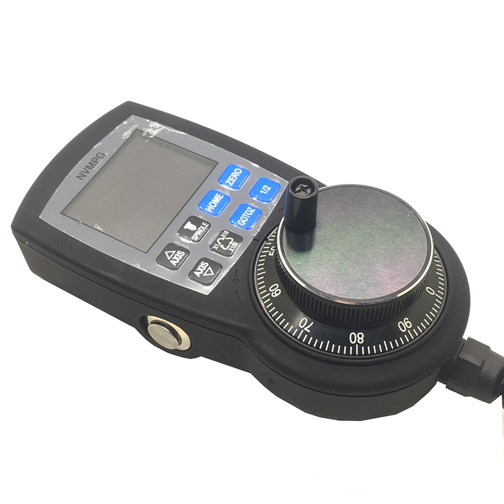
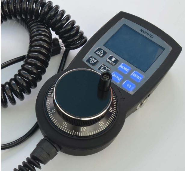
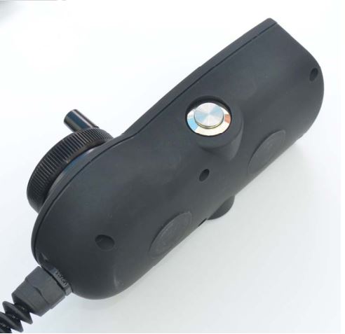
Product appearance and dimension
NVBDH+ product appearance pls see picture 1-1 to 1-3.
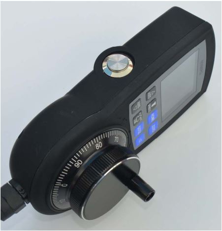
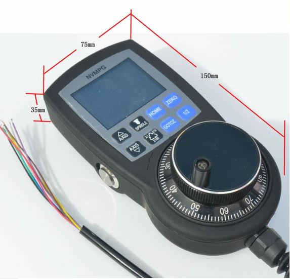
Product size is 150*75*35mm,as picture 1-6 shows.
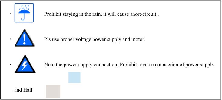
Notice and Waring
Chapter 2. Connection
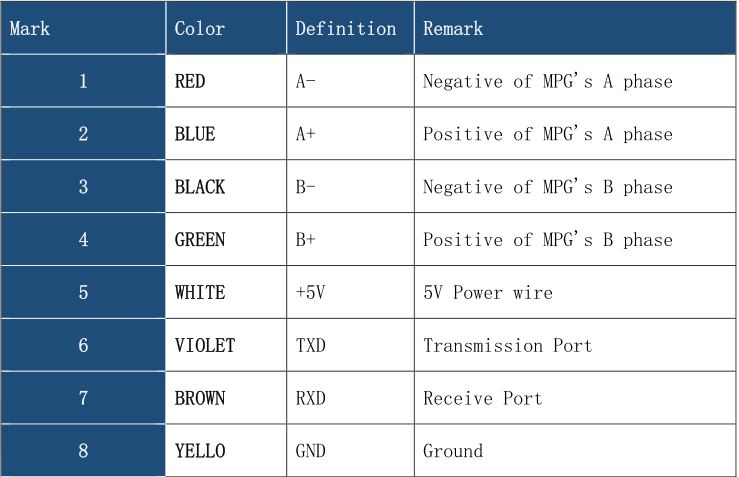
Connection interface definition
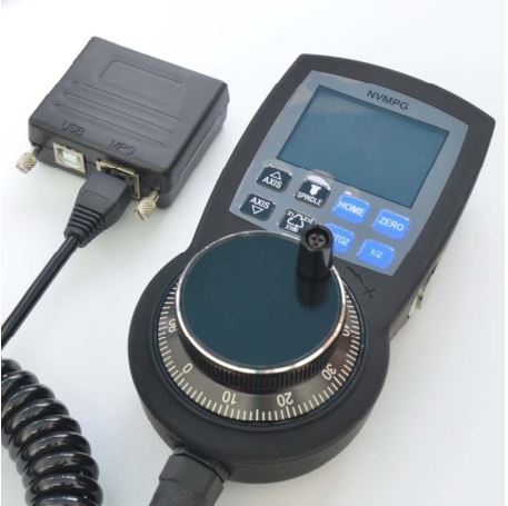
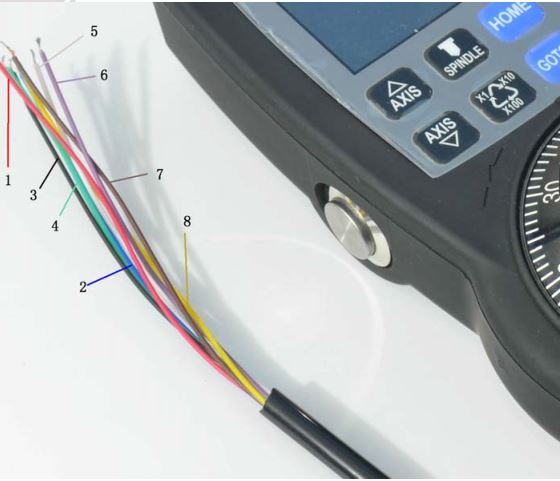
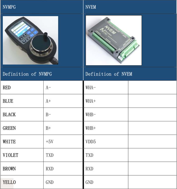
NVMPG has 8 wires connected to CNC system, the definition of NVMPG see as Chart 2-1.
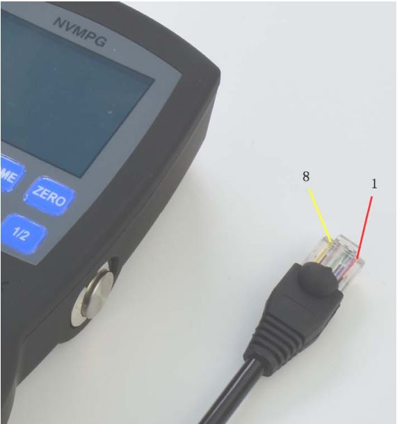
There are 2 mode of terminal, which are open wire(see as Figure2-1) and RJ45 port(see as Figure 2-2).
RJ45 port mode is only compatible with NC200. See as Figure 1-5.
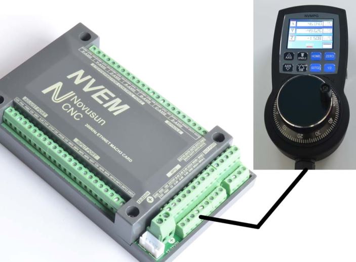
NVMPG connection
NVMPG can be connected to NVEM/NVUM and NC200. NVMPG and NVEM connecting method see as Figure 2-3 and Chart 2-2.
Connection between NVMPG and NC200 is very simply, it’s only need to put NVMPG’s RJ45 plug into NC200’s RJ45 socket. See as Figure 1-5.
Chapter 3. Configuration & Use
There are 2 DLL file we provide. If we use standard MPG, we should use NVEM_F.DLL, or if we use NVMPG, we should use NVEM_UART_F.DLL.
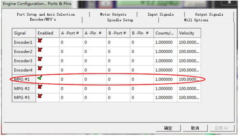
First we need to set MPG to valid, see as Figure 3-1. No need to set other parameter.
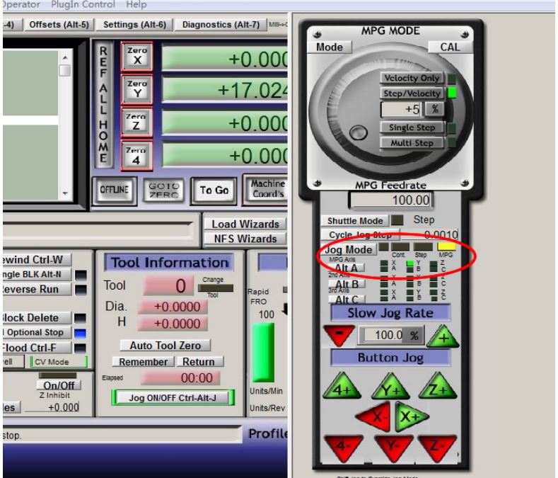
Second, if we need to use MPG, we should change Manual operation mode into MPG mode, see as Figure 3-2.
Use
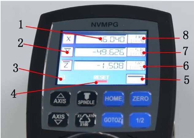
See as Figure 3-3,it’s definition of NVMPG’s screen. Specific description is as follows.
- Coordinate value of 6 axis
- Axis identification
- MPG rate.
- State of RESET.
- State and value of Spindle
- Value of SRO
- Value of SJR
- Value of FRO
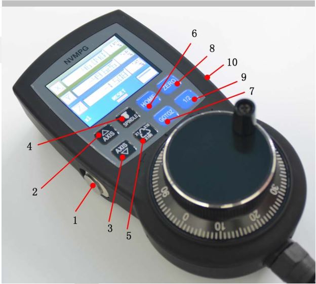
See as Figure 3-4, there are 10 buttons in NVMPG. Each key has a function. We list the function of these buttons in Chart 3-1.
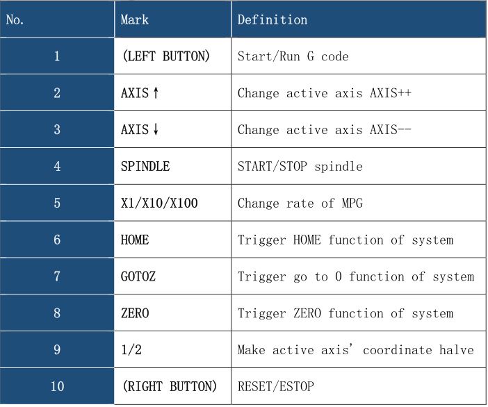
- Button 1(START) : After loading G code, push this button to run G code.
- Button2(AXIS↑):
- Button3(AXIS↓) : AXIS↑ and AXIS↓ are 2 button for change active axis. Each axis has a block above the axis label. Active axis’ block is yellow, and invalid axis’ block is black. You can notice the color of the block when you change active axis.
- Button4(SPINDLE) : Open or shut down the spindle.
- Button5(X1/X10/X100) : Change the rate of MPG, The rate of MPG is displayed on the screen.
- Button6(HOME) : Push this button is making machine to find it’s Machine zero port. If we set a active axis, e.g. X, then push this button is going to find X axis’ machine zero port. Or if we set no active axis, then push this button is going to find all axes’ machine zero port.
- Button7(GOTOZ) : Push is button is making machine to go to workpiece zero port. The method refer to button 6.
- Button8(ZERO) : Push this button is making current coordinates to 0. The method refer to button 6.
- Button9(1/2) : Push this button is making current coordinates halve. The method refer to button 6.
- Button10(RESET) : This button is RESET function.
Chapter 4. Contract us
MPG With Display NVMPG User Manual – MPG With Display NVMPG User Manual –