User Manual
![]()
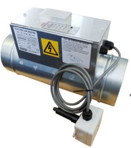
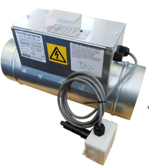
Thyristor Controlled Electric Heater
1.0 SAFETY INFORMATION
- The provision of the electrical supply and the connection of the unit to the mains must becarried out by a qualified electrician.
- Isolate from power supply before removing any covers. During installation / maintenance ensure all covers are fitted before switching on the mains supply.
- All-pole disconnection from the mains as shown in the wiring diagram must be incorporated within the fixed wiring and shall have a minimum contact separation of 3mm in accordance with latest edition of the wiring regulations.
- This unit must be earthed.
- Ducting must be securely fixed with screws to the spigot to prevent access to live parts. Duct runs terminating close to the fan must be adequately protected by suitable guards.
- If the supply cord is damaged, it must be replaced by the manufacturer, its service agent orsimilarly qualified persons in order to avoid a hazard.
- This appliance should not be used by children or persons with reduced physical, sensory ormental capabilities or lack of experience and knowledge, unless they have been given supervision or instruction concerning the safe use of the appliance by a person responsible for their safety. Children shall not play with the appliance. Cleaning and user maintenance shall not be carried out by children.
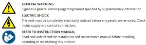
1.1 Symbols
1.2 Important Information
This manual contains important information on the safe and appropriate assembly, transport, commissioning, operation, maintenance, disassembly and simple troubleshooting of the product.
While the product has been manufactured according to the accepted rules of current technology, there is still a danger of personal injury or damage to equipment if the following general safety instructions and the warnings contained in these instructions are not complied with.
- Read these instructions completely and thoroughly before working with the product.
- Keep these instructions in a location where they are accessible to all users at all times.
- Always include the operating instructions when you pass the product on to third parties.
- When resetting the thermal cut-out, the heater may suddenly switch on and element terminals, etc. will become live.
1.3 Personal Protective Equipment
The following minimum Personal Protective Equipment (PPE) is recommended when interacting with Nuaire product:
- Protective Steel Toed Shoes – when handling heavy objects.
- Full Finger Gloves (Marigold PU800 or equivalent) – when handling sheet metal components.
- Semi Fingerless Gloves (Marigold PU3000 3DO or equivalent)– when conducting light work on the unit requiring tactile dexterity.
- Safety Glasses – when conducting any cleaning/cutting operation or exchanging filters.
- Reusable Half Mask Respirators – when replacing filters which have been in contact with normal room or environmental air. Nuaire would always recommend a site specific risk assessment by a competent person to determine if any additional PPE is required.
2.0 INTRODUCTION
Specifically designed to act as pre or re-heaters in small branch ducts from a main AHU or on systems where the supply fan is controlled from elsewhere.
Designed for simple installation into standard spiral ductwork systems the heater operates automatically via the dictate of the temperature setting and duct mounted temperature sensor to pulse the heater on and off to maintain a constant supply air temperature. The temperature set-point is adjustable 0-40 °C.
Similar to other in-built thyristor controllers the unit has a temperature set-point control on the front facia and indicator lamps to show the status. The heater units come with a pre-wired high temperature manual reset cut-out, a pre-wired duct mount combined airflow proving and temperature sensor on a 1.5-2 metre fixed lead. This should be mounted a minimum of 1 metre after the heater in the supply air duct.
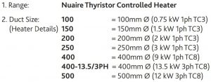
2.1 NALTCH100-250 (TC3) Thyristor Control The TC3 thyristor controller is designed for use with heaters up to and including 3kW single phase. There is no fan run-on timer so the heater relies on a volt-free or 230V start signal and stays off until airflow is detected by the combined airflow and temperature sensor.
The TC3 thyristor control is supplied for units with heater duties from 0.75 to 3kw.
2.2 NALTCH400-500 (TC8) Thyristor Control The TC8 thyristor temperature control panel controls a 220/250V single phase 2 step heater up to 2 X 19A (9.0kW) with an additional relay and has 5A fused outputs for single phase supply and extract fans up to a maximum of 4.5A each.
Although the TC8 has been designed primarily for single phase heater loads up to 9.0kW, it has a SSR (Solid State Relay) output which can be used to control larger three phase (380/430V) heater loads up to 42kW.
2.3 Code Description:

3.0 MECHANICAL INSTALLATION
Installation must be completed by competent persons, in accordance with good industry practice and should conform to all governing and statutory bodies i.e. IEE, CIBSE, etc.
- Unpack the heater taking care to ensure items and paperwork are removed from the centre of the heater duct.
- The terminal box may also contain wiring instructions. If you are only installing the heater in the air duct, leave these instructions for the electrician.
- The heater can be installed into an ISO standard spiral duct run with either horizontal or vertical flow. With vertical ducts consideration must be given to items in the run above the heater which could be damaged by heat rising when the fan is switched off. All heaters should be kept away from plastic conduits or materials easily damaged by heat. Allow for casing temperature of 100°C (ideal minimum air velocity = 2m/s).
- To install a heater, measure between the ridged rings and cut the spiral to suit. Use high temperature sealant and pop rivets to fix.
- These heaters must not be installed outside unprotected or in areas that are washed down.
- Do not use flexible connectors directly onto the heater. The best position for the terminal box is on the side of a horizontal duct. Ensure access to the terminal box is possible. Make sure lagging etc. does not cover the terminal box.
- A combined temperature and airflow sensor will be found attached to a coiled lead. This should be mounted in the duct 1 to 2 metres downstream from the heater where the sensor cannot be damaged by heat. A 20mm(TC3) / 25mm(TC8) holesaw and 2 PK fixing screws will be required.
- The sensor has an airflow direction arrow and will only operate if installed with the arrow pointing in the direction of airflow.
4.0 ELECTRICAL INSTALLATION
Every system should have an isolator switch which can be locked in the off position to prevent accidental reconnection during maintenance. When resetting the thermal cutout, the heater may suddenly switch on and element terminals, etc. will become live.
Ensure the heater is correctly earth bonded. Terminal covers must be secured after inspection and should be labelled “DISCONNECT SUPPLY BEFORE REMOVING THIS COVER”. It is the installer’s responsibility to ensure the installation meets all current Health & Safety Regulations.
All wiring must be carried out by a qualified electrician in compliance with the latest regulations. These units are internally pre-wired and require only a suitable supply feed connection to operate (see rating label).
4.1 NALTCH-(100-250) (TC3)4.1.1 NALTCH-(100-250) (TC3) PCB

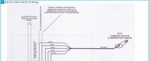
4.1.2 NALTCH-(100-250) (TC3) Wiring
4.2 NALTCH-(400/500) (TC8)If the option to feed the fans is not used and the supply fan is not local to the heater, it is possible to use only the sensed airflow to switch on the heater. The output air temperature will be as set on the face of the panel. If you need to switch the heater off from a remote time clock, remove the link provided and wire from the clock.
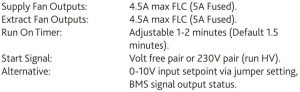
The TC8 controller has two 1ph fan outputs (4.5A max) which, if used, run the fan on for 2 minutes after the time clock switches off the heater. Other features are available, please refer to NALTCH-(400/500) (TC8) connections and settings.
4.2.1 NALTCH-(400/500) (TC8) PCB

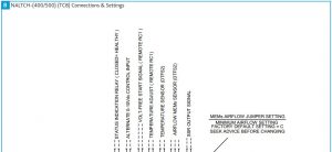
4.2.2 NALTCH-(400/500) (TC8) Connections & Settings

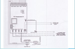
4.2.3 NALTCH-400 (TC8) Wiring

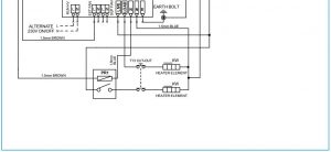
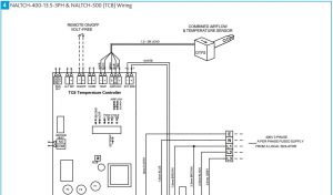
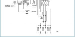
4.2.4 NALTCH-400-13.5-3PH & NALTCH-500 (TC8) Wiring
5.0 CONTROLS
Take care when using remote fan speed controllers not to let the air velocity drop too low. Also try to avoid using the controller to switch the system off as this can lead to nuisance tripping of the high temperature cutout in the heater.
5.1 NALTCH100-250 (TC3)
With the unit powered but not yet enabled via the volt-free ON/OFF terminals, the yellow POWER lamp will be lit. The red AIRFLOW FAILED lamp will also be lit if the supply air fan is not running.
Under normal working conditions with the volt-free ON/OFF terminals connected, the unit will display the yellow lamp with the red HEATER ON lamp either on or pulsing according to the heat demand.
If the red AIRFLOW FAILED lamp is lit, there is either insufficient airflow or the combined sensor has not been fixed into the ductwork correctly. There is an airflow direction Indicator arrow on the sensor and the unit will only operate when this is correctly installed.
5.1.1 NALTCH100-250 (TC3) LED Indicators
POWER ON – YELLOWAIRFLOW FAILED – REDHEATER HEALTHY – GREENHEATER ON – RED
5.2 NALTCH400-500 (TC8)

5.2.1 NALTCH400-500 (TC8) LED Indicators
AIRFLOW FAULT – REDPOWER ON – YELLOWHEATER ON – RED (solid or flashing, indicting pulsed control)SUPPLY FAN ON – GREENEXTRACT FAN ON – GREEN
6.0 MAINTENANCE
It is important that maintenance checks are recorded and that the schedule is always adhered to, in all cases, the previous report should be referred to.
6.1 Annually
- Before carrying out any maintenance ensure the electricity supply has been isolated.
- Check all electrical connections for tightness and broken terminations.
- Check all wiring for deterioration or overheating.
- Check unit for dirt or dust and wipe clean (except elements).
- Check the element section for obstructions or debris.
- Check all components for wear and physical damage.
- Check all safety devices for proper operation.
- Check temperature controls for proper operation as per the installation instructions.
- Check all inlet filters and replace where necessary.
- Ensure unit has been installed as per the installation instructions.
7.0 WARRANTY
The 1 year warranty starts from the day of delivery and includes parts and labour for the first year.
This warranty is void if the equipment is modified without authorisation, is incorrectly applied, misused, disassembled, or not installed, commissioned and maintained in accordance with the details contained in this manual and general good practice.
The product warranty applies to the UK mainland and in accordance with Clause 14 of our Conditions of Sale. Customers purchasing from outside of the UK should contact Nuaire International Sales office for further details.
Failure to maintain the unit as recommended will invalidate the warranty.
8.0 END-OF-LIFE AND RECYCLING
Where possible Nuaire use components which can be largely recycled when the product reaches its end-of-life:
- Fans, motors, controls, actuators, cabling and other electrical components can be segregated into WEEE recycling streams.
- Sheet metal parts, aluminium extrusion, heating/cooling coils and other metallic items can be segregated and fully recycled.
- EPP, plastic ducting, nylon corner pieces, plastic heat exchangers, packaging material and other plastic components can be segregated into mixed plastic and widely recycled.
- Cardboard packaging, wood, used filters and other paper components can be largely recycled or fully processed in energy from waste centres.
- Remaining Items can be further segregated and processed inb accordance with the zero waste hierarchy. Please call After Sales Support for further information on items not listed above.
Ensure that Nuaire product is made safe from any electrical / water / refrigerant supplies before dismantling commences. This work should only be undertaken by a qualified person in accordance with local authority regulations and guidelines, taking into account all site based risks.
9.0 AFTER SALES AND REPLACEMENT PARTS
For technical assistance or further product information, including spare parts and replacement components, please contact the After Sales Department.
If ordering spares please quote the serial number of the unit together with the part number, if the part number is not known please give a full description of the part required. The serial number will be found on the identification plate attached to the unit casing.
Telephone 02920 858 400
Technical or commercial considerations may, from time to time, make it necessary to alter the design, performance and dimensions of equipment and the right is reserved to make such changes without prior notice.
Thyristor Controlled Electric Heater User Manual – Thyristor Controlled Electric Heater User Manual –
[xyz-ips snippet=”download-snippet”]