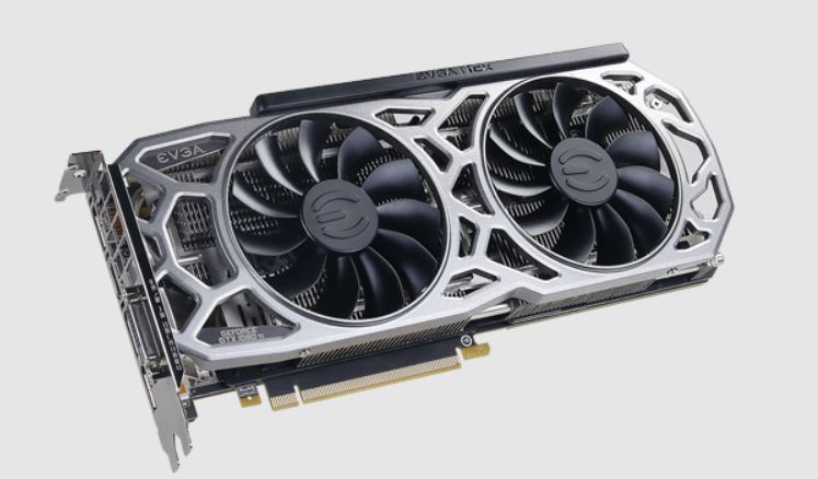
Nvidia EVGA GeForce GTX 1080
Ti Installation Guide

The following instructions and pictures are provided to assist your installation of the EVGA Gn<™ 1080 Ti SC HYBRID Cooling Kit to the EVGA GeForce GTX™ 1080 Ti graphics cards. Please be careful installing the Kit; there are several very small fasteners used that can be stripped if you are not careful.
Please be sure to keep your original shroud, heatsink, and screws so your card can be returned to its original condition in case you ever need to submit for warranty.
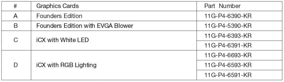
The instructions below will walk you through the removal of the original heatsink and fan(s), and installation of the EVGA HYBRID module and replacement shroud. Please see below for SKU’s compatible with this cooler:
Included Accessories:
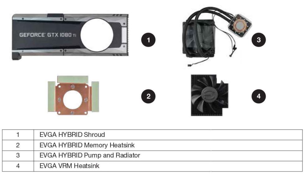
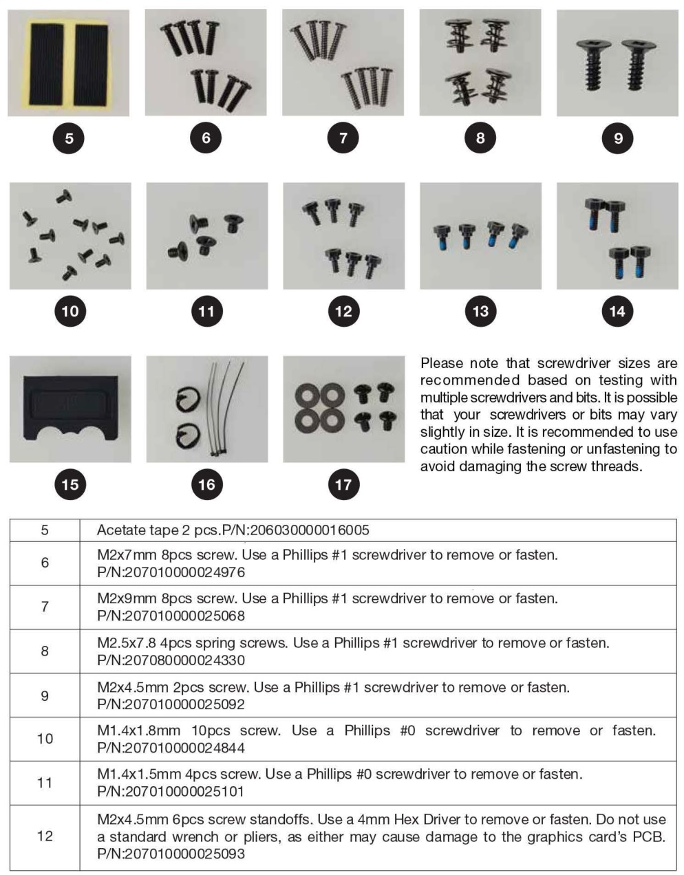
*Please note that the accessory list above covers all items expected to be included in the SC HYBRID Kit. It is possible that you may receive extra accessories that will go unused after completion of the installation manual. Please follow all directions carefully, and contact EVGA Customer Service if you have any missing accessories or questions.
See the instructions below.
01. Remove the backplate from the card
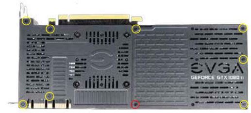
(a) For Founders Edition #A, remove 16 screws on the back side of the card. Use a Phillips #1 screwdriver for the 2 screws near the bracket, circled in yellow, and a Phillips #0 for the remaining 14, circled in red. This allows the backplate to be removed. Carefully set these aside, as these screws will not be used again.

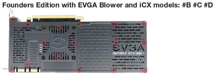
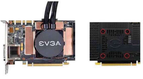
(b) For Blower and iCX models #B, #C, #D, remove the 16 screws circled in the picture below, using a Phillips #1 screwdriver. This allows the backplate to be removed. Carefully set these aside, as these screws will not be used again.
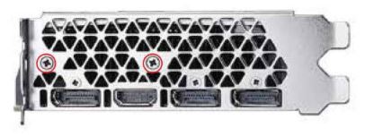
2. For Founders Edition (#A), remove the screws circled on the bracket below with a Phillips #1 screwdriver and set the screws aside, as these will not be used again.
3. Remove the remaining screws on the back of the card.
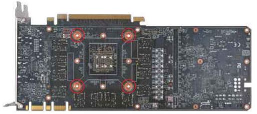
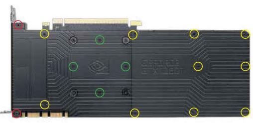
(a) For Founders Edition models (#A), use a Phillips #1 screwdriver to remove the 4 spring screws and a 4mm Hex driver to remove the remaining 14 standoff screws circled below. This will allow the thermal module to be removed. Carefully set these aside, as these screws will not be used again.
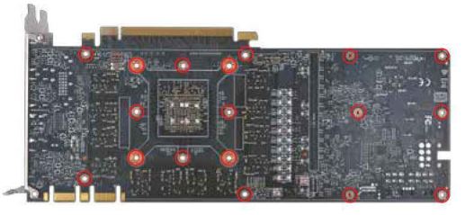
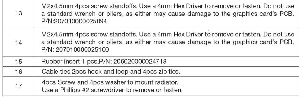
(b) For EVGA Blower models and all iCX models (#B,#C,#D), use a Phillips #1 screwdriver to remove the 4 spring screws circled below. This allows the thermal module to be removed. Carefully set these aside, as these screws will not be used again.
4. Remove heatsink and fan, while carefully disconnecting fan and LED connectors.
(a) For all cards, carefully remove the original heatsink and fan. You may need to gently twist the thermal module to loosen up the heatsink from the thermal pads and GPU thermal grease. Once loose, gently lift the side of the heatsink to expose the fan and LED wires/headers. Depending on your card model, you may have up to 2x fan headers and 1 x LED header.
(b) Please be careful when removing the fan and LED headers; the wires can snap if pulled too hard. The safest way to remove the connectors is with a small flat-head screwdriver, tweezers, or fingernails to raise the edge of the headers a little at a time. It is recommended to remove the LED header (left circle) before removing any fan headers (right circle). After removing the headers, set aside the heatsink/fan; it will no longer be needed for this Kit.

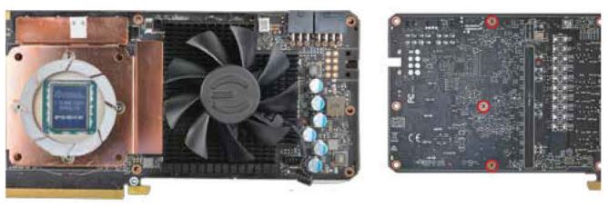
5. Clean the card for installation:Remove all thermal grease on the GPU and remove any pads that stick on the PCB. Clean the GPU with high-percentage isopropyl alcohol and a lint-free cloth. You may try to reattach the thermal pads to the same location on the original cooler in case you need to return the card to its original state for warranty purposes. After you are finished cleaning, the card should look like these photos:

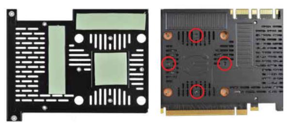
6. Install the memory baseplate
(a) Remove protective tape on the bottom of the #2 memory baseplate. Next, install the memory baseplate as shown in the left photo below. For Founders Edition cards (#A), hold the copper plate in place and turn the card over. Tighten 4 #14 standoff screws, as shown in the right photo below.

(b) If you have a Blower or iCX model (#8,#C,#D), please check to make sure that your thermal pads are in the same location as the left photo below. If not , please check the back of the card in case the matching thermal pad remains on the card. Install the memory baseplate, as shown in the left photo above. Hold the copper plate in place and turn the card over. Place the right backplate over the card and tighten the backplate with 4 #6 screws, as shown in the right photo below.
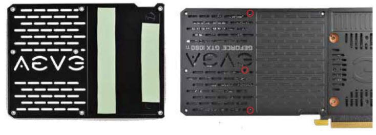
7. Install the MOS-FET heatsink
(a) Remove protective tape on the bottom of the heatsink. Next, install the #4 heatsink as shown in the left photo below. For Founders Edition cards (#A), hold the heatsink in place and turn the card over. Tighten 3 #13 screws, as shown in the right photo below.
(b) If you have a Blower or iCX model (#B,#C,#D), please check to make sure that your thermal pads are in the same location as the left photo below. If not, please check the back of the card in case the matching thermal pad remains on the card. Install the heatsink, as shown in the left photo above. Hold the heatsink in place and turn the card over. Place the left backplate over the card and tighten the backplate with 3 #6 screws, as shown in the right photo below.
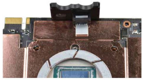
8. For all cards, install #15 rubber insert onto the metal post and make sure the grooves are facing upwards.
9. Install pumpFor all cards, carefully remove the plastic cover over the #3 pump without touching the thermal grease. Install the pump over the memory baseplate, as shown in the left photo below. Place the radiator fan wire in the middle of the grooves. Next, turn the card over while holding the pump in place. Fasten the pump to the card using 4 #8 spring screws, as shown in the right photo below:
10. Install pump power cable
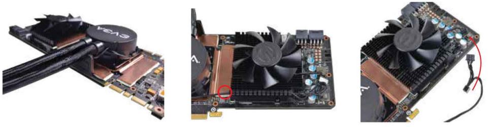
(a) For all cards, run the power connector with a Y adapter around the tube and pump. Next, use #5 acetate tape and a #16 cable tie (if necessary) to secure the wire (See left photo). Run the wire under the groove of the MOSFET heatsink and plug the power adapter into the fan header. Use acetate tape to secure the wire to the heatsink (See middle photo). Finally, plug the MOSFET fan cable into the passthrough connector (See right photo).
11. Connect LED wire and install shroudFor all models, connect the LED cable to the card based on the type of graphics card used:
1. 2 Pin: Plug into O if you have (#A,#B,#C) models2. 6 Pin: Plug into 8 if you have (#D) models

12. HYBRID radiator fan cableMake sure the radiator fan cable runs in the middle of the rubber grooves before you install the shroud.
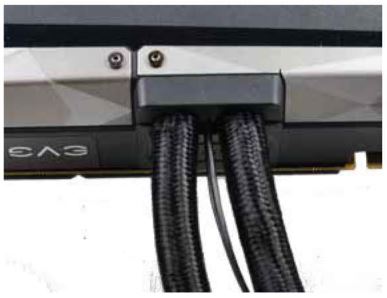
13. Install the shroudInstall the #1 shroud onto the card, making sure the shroud is beneath the edge of the bracket, and fits into the grooves on the rubber insert:

14. Reinstall the backplate and finish
(a) For Founders Edition cards (#A), tighten 6 #12 screws, circled in red, and 1 #13 screw, circled in yellow, as shown in the photo below.

(b) For Founders Edition cards (#A), tighten 2 #9 screws circled in red, 10 #10 screws circled in yellow, and 4 #11 screws circled in green.
(c) For Blower model and iCX cards (#B,#C,#D), tighten 8 #7 screws circled in yellow, and 1 #6 screw circled in red.
(d) Once the backplate has been fastened, the HYBRID installation is complete.
Mounting the Radiator
- To mount the radiator, it is recommended that the radiator be installed at a level above the HYBRID graphics card. This will reduce pump noise and the potential to create an air bubble in the loop .
- The radiator will fit mounting holes designed for a 120mm x 120mm case fan.
- The default setting for the HYBRID’s radiator/fan is to blow through the radiator and outside the chassis. For that reason, we recommend installing the radiator at the back or top of the chassis.
- If installing the radiator in the back of the chassis, we recommend positioning the tubes at the bottom of the radiator.
- Make sure that you leave some slack in the tubing lines to prevent damage to the tubing or internal fittings. If the tubes are twisted too much or pulled too tightly, you may cause damage to the pump/radia tor or cause the HYBRID kit to begin leaking.
- When ready, line-up the radiator with the mounting holes on the chassis. On the outside of the chassis use #17 washers and screws to fasten the radiator to the chassis.
- Once fully mounted, use the remaining #16 cable ties to secure the radiator fan wire to the tubing.
- Your EVGA GTX 1080 Ti SC HYBRID Kit installation is now fully complete!
Important Information
EVGA GTX™ 1080 Ti SC HYBRID Kit is an AIO Water Cooling System. You do not need to add any coolant , and the system is completely self-contained. EVGA GTX™ 1080 Ti SC HYBRID Kits have been leak-tested at the factory before shipping to customers.
EVGA GTX™ 1080 Ti SC HYBRID Kits are exclusive only to the NVIDIA® reference PCB for GTX™ 1080 Ti graphics cards and EVGA GTX™1080 Ti graphics cards and were not designed to fit any other graphics cards.
Warranty for the GTX™ 1080 Ti SC HYBRID Kit
Your EVGA GTX™ 1080 Ti SC HYBRID Kit comes with a 1 (one) year warranty. Refer to your GTX™ 1080 Ti manufacturer’s warranty information before installing the EVGA GTX™ 1080 Ti SC HYBRID Kit. Should you damage your GTX™ 1080 Ti graphics card during the installation process , EVGA will not be held responsible for any physical damage of your EVGA GTX™ 1080 Ti SC HYBRID Kit, case, motherboard or any associated hardware when damage is caused by improper installation.
Note
_________________________________________________________________________
_________________________________________________________________________
_________________________________________________________________________
_________________________________________________________________________
E009-00-000201
[xyz-ips snippet=”download-snippet”]