NVISION Junior Racer RTF

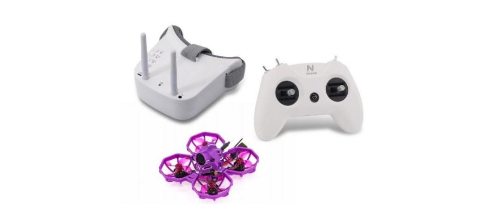
Junior Racer Whoop Drone include
1x Junior Racer(with Frsky XM+ Receiver)1x Radio(support Frsky XM+)1x fpv goggles1x B3 Charger1x 300mAh 3S 45C Battery2x Lipo Battery Strap1x Props Removal Tool2x fpv goggles Dipole 5.8G Antennas1x GEMFAN 1636 4-blade Propeller(4pcs)1x Nylon Cable Tie(5pcs)1x M1.4*6mm Screw(6pcs)
Operate Junior Racer Whoop Drone
*Power On/Off:
connect the power cable to Junior Racer 75 the battery, the power LED, receiver LED and FC LED are on, then the FC LED flashes and the receiver LED turns off. After use, unplug the connection, and all LED will turn off.
*Battery:
connect the battery to the voltage tester to display the current-voltage value of the battery.
*Charge:
connect the battery to the charger supplied with the adapter or other 5V power. The LED will show a red light when charging; the LED will show a green light when finishing charging.
F411 12A AIO FC
FC Parameters:
CPU: STM32F411CEU6Six-axis: MPU6000 (SPI connection)Size: 29mmx29mmFirmware version: Betaflight TCMM-F411RC sharing: UART1-RXOSD: Built-in Betaflight OSD (STM32 controls the OSD chip through SPI in DMA mode) Receiver: Support FrskyXM/XM+ receiver/Futaba receiver/Flysky receiver/TBS Crossfire receiverSupport programmable LED such as WS2812Built-in current sensorReserved buzzer interfaceReserve DJI portWeight: 5.07g
ESC Parameters:
Support: PWM, Oneshot125, Oneshot42, Multishot, Dshot150, Dshot300, Dshot600Input voltage: 2S-4SLipoContinuous current: 12APeak current: 20AFirmware: BLHELI_SProcessor: SILABSEFM8BB21F16GMotor connector: 1.25mm pin header connector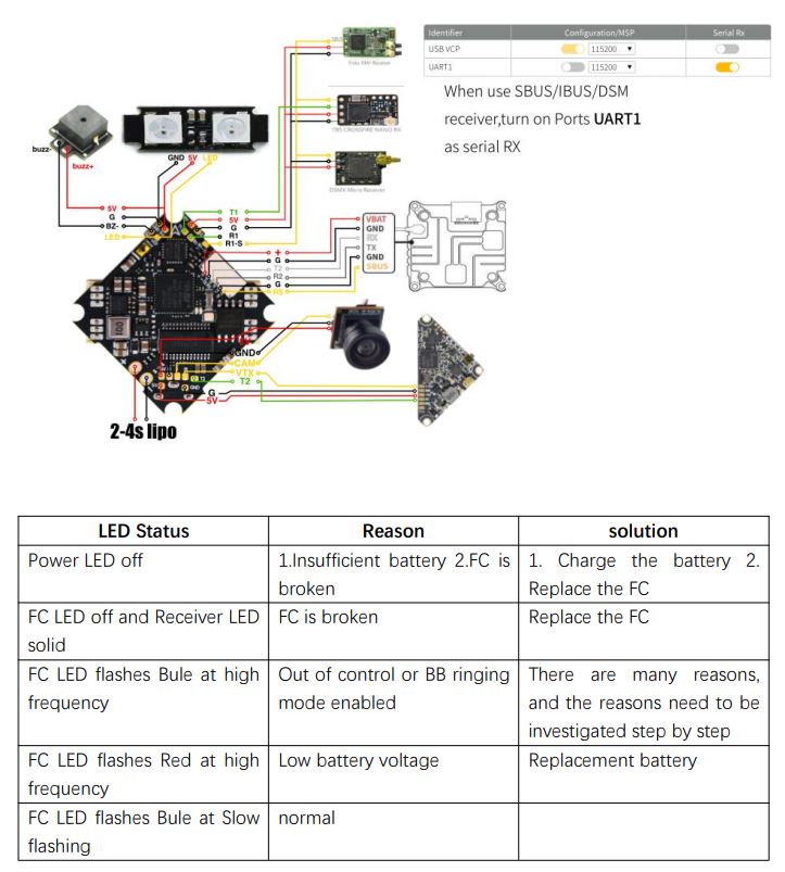
Operate the radio

-
Install Battery:
remove the back cover of the transmitter, connect the battery inside to the power interface correctly, and install the back cover.
-
Power On
Long press the power button for about 3 seconds, then pull the throttle to the lowest position, release the button after the radio vibrates twice, and the power indicator turns from green to blue, indicating that the radio is turned on.
-
Binding:
1. First press and hold the bind of the receiver, and then power on the aircraft (the receiver’s traffic light is always on at this time)2. After the remote control is turned on, short press the Bind button on the back of the remote control, the power indicator will be red The color and blue flash alternately and enter the linking state for about 10 seconds.3. If the receiver flashes red, it means the linking is successful4. After successful linking, the aircraft can be used again after power on
If it is unsuccessful, repeat the above actions and link again. When the throttle is hit to the lowest level, the toggle switches A to unlock, and the motor starts to rotate.
-
Power Off
Press and hold the power button for about 5 seconds, release the button after the transmitter vibrates, and the power indicator light turns off, the transmitter is turned off.
-
Charge:
the power indicator light flashes blue slowly and vibrates when the battery approaches the low voltage limit. it needs to be stopped immediately. Connect the USB cable to the power supply, and the power LED will show
·red when charging;
the power LED turns off after the charging process is done.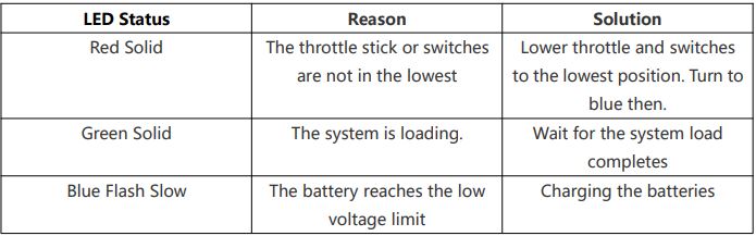
NVISION A01 VTX
Description:
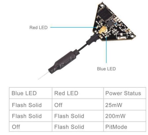
*Switchable power includes 0mW, 25mW and 200mW.*This VTX includes the SmartAudio function. The flight controller can use the audio cable to communicate with the video transmitter. It allows the flight controller to know the frequency used by the VTX and make changes.*This VTX supports PitMode.*Dipole whip high sensitivity antenna. It is mounted to the VTX board durable.*Output power: 0mW, 25mW and 200mW (adjustable)*Power supply voltage: 5V. Does not support direct connection to 1S battery*Weight: 2.0g*Frequency: 5.8GHz 6 frequency band 48 channels, competition frequency band: 5362~5945MHz
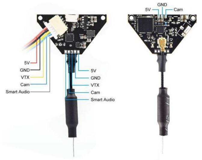
Component Layout Diagram for NVISION A01 VTX:
How to Change Frequency & Channel & Power
Only support frequency and power change through the SmartAudio interface.
Method 1: Use the OSD menu.
Enter the OSD menu by radio transmitter sticks ( Pitch Stick UP and Yaw Stick Left). Then FEATURES -> VTX SA to change the frequency and power.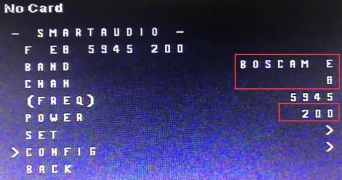
Method 2: Use the Betaflight GUI command.
We could also use the Betaflight CLI commands to change the frequency and power of the VTX.For example, set the frequency to 5865 and power to 200mW ( 1 for 25mW / 2 for 200mW);set vtx_band=1set vtx_channel=1set vtx_freq=5865set vtx_power = 2save
How to Use the PitMode
PitMode allows racers to power up their video transmitters during race events without interfering with other racers and still having the ability to change VTX settings or do some testing. The range is limited to 2-3m and transmission happens on the selected frequency. The PitMode is active when only red LED flashes solid.
How to active the PitMode: Enter the OSD menu by radio transmitter sticks.FEATURES -> VTX SA -> CONFIG -> PIT FMODE. Then select the PIR status.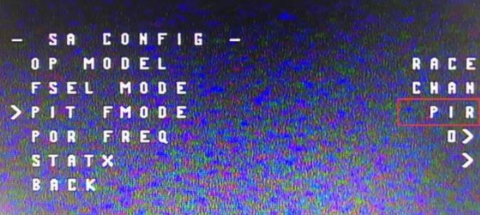 How to exit the PitMode: As the same above, select the OP MODEL to FREE to close the PitMode. Then the VTX will recover to the 25mW power status.
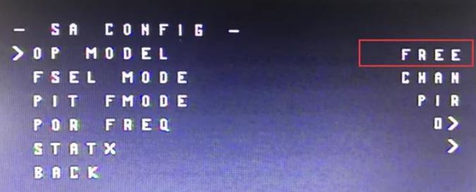
TRANSMISSION FREQUENCY TABLE
This A01 VTX could support 3 frequency table according to your local law. The tables below are for all the frequency is valid.USA frequency table below. The frequency in the red item is invalid.![]()
[xyz-ips snippet=”download-snippet”]