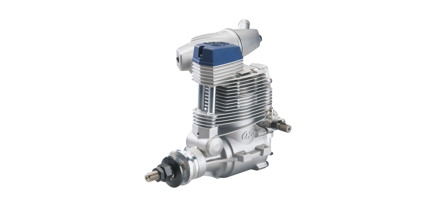
O.S. ENGINE4 stroke gasoline engine for airplanesInstruction Manual
It is of vital importance, before attempting to operate your engine, to read the general ‘SAFETY INSTRUCTIONSAND WARNINGS’ in the following section and to strictly adhere to the advice contained therein.
- Also, please study the entire contents of this instruction manual, so as to familiarize yourself with the controls and other features of the engine.
SAFETY INSTRUCTIONS AND WARNINGS ABOUT YOUR O.S. ENGINE
Remember that your engine is not a ” toy “, but a highly efficient internal-combustion machine whose power is capable of harming you, or others, if it is misused or abused. As owner, you, alone, are responsible for the safe operation of your engine, so act with discretion and care at all times. If at some future date, your O.S. engine is acquired by another person, we would respectfully request that these instructions are also passed on to its new owner.
- The advice which follows is grouped under two headings according to the degree of damage or danger which might arise through misuse or neglect.
WARNINGS: These cover events which might involve serious (in extreme circumstances, even fatal) injury.
NOTES: These cover the many other possibilities, generally less obvious sources of danger, but which, under certain circumstances, may also cause damage or injury.
WARNINGS:
- Never touch, or allow any object to come into contact with the rotating propeller and do not crouch over the engine when it is running.
- Gasoline is poisonous. Do not allow it come into contact with the eyes or mouth. Always store it in a clearly marked container in a cool and dark place and out of the reach of children. There is a possibility that it may damage your health.
- Gasoline is highly flammable. Keep it away from an open flame, excessive heat, sources of sparks, or anything else which might cause it to ignite. Do not smoke or allow anyone else to smoke near to it.
WARNINGS:
- Carry out the mixing of the gasoline and oil outdoors or in a well ventilated place away from any source of fire to prevent the possibility of a fire.
- Refill the fuel tank only after the engine is well cooled down, or there is a danger of fire.
- Model engines generates considerable heat. Do not touch any part of your engine until it has cooled. Contact with the muffler (silencer), cylinder head or exhaust header pipe, in particular, may results in a serious burn.
- Observe the laws and regulations in each country and district concerning the usage, transportation and storage of gasoline. Ask details at fire station in each district.
- Never operate your engine in an enclosed space. Model engines, like automobile engines, exhaust deadly carbon-monoxide. Run your engine only in an open area.
- Do not operate the engine nor model alone, or there is a possibility of injury.
NOTES
- Any propeller requires utmost attention to handle.Be sure to follow the instruction manual supplied with a propeller.
- This engine was designed for model aircraft.Do not attempt to use it for any other purpose.
- Start the engine only after installing it in the model.Do not start the engine before installing it in the model, or there is a possibility of injury.
- Be sure to use an effective silencer (muffler).Frequent exposure to an open exhaust may eventually impair your hearing. Such noise is also likely to cause annoyance to others over a wide area.
- Mount the engine in your model securely, following the manufacturers’ recommendations.
- For their safety, keep all onlookers (especially small children) well back (at least 10 meters) when preparing your model for flight.
- When checking a spark plug with the power source on, do not hold the plug, plug cap, high tension cord , or you will get a shock.
- Install a top-quality propeller of the diameter and pitch specified for the engine and aircraft.
- Discard any propeller which has become split, cracked, nicked or otherwise rendered unsafe.Never attempt to repair such a propeller: destroy it.Do not modify a propeller in any way.
- Install the propeller on the shaft so that the curved face of the blades faces forward – i.e. in the direction of flight. Firmly tighten the propeller washer and propeller installing screws using the correct size wrench. Always check the tightness of propeller installing screws and retighten them, if necessary, before starting the engine. Also, check the tightness of all the screws and nuts before restarting the engine.
- Always check the throttle linkage.If it is disconnected,throttle action becomes uncontrollable, which mayresult in a serious accident.
- Take care that loose clothing (ties, shirt sleeves, scarves, etc.) do not come into contact with the propeller. Do not carry loose objects (such as pencils, screwdrivers, etc.) in a shirt pocket from where they could fall through the propeller arc.
- Use an electric starter for this engine. The wearing of safety glasses is also strongly recommended.If you try hand starting, be sure to use a chicken stick or heavy glove. Never attempt to start the engine with a bare hand.
- Be sure to carry out adjustments of the needle valve and mixture control valve after stopping the engine.
- Do not start your engine in an area containing loose gravel or sand. The propeller may throw such material in your face and eyes and cause injury
- If you have to carry the model to the take-off point with the engine running, be especially cautious.Keep the propeller pointed away from you and walk well clear of spectators.
- Switch off the ignition module to stop the engine or fully close the throttle valve via the transmitter to shut off the fuel supply. Otherwise there is a possibility of injury.
- Immediately after the engine is stopped, the engine may start with a crank even when the igniter switch is off. Do not crank the engine, or there is a possibility of injury.
- Be sure to install an externally operable switch for the ignition system battery to stop the engine if it is started unintentionally with the radio transmitter turned off or there is the possibility of injury.
- Connect the throttle linkage so that the engine can be stopped via radio operation.
ABOUT THE ENGINE
While this is a four stroke gasoline engine, use the same oil mixed gasoline for two stroke gasoline engines.
- This engine is designed for experienced fliers.
- Beginners and newcomers should not use this engine.
- A modified new carburetor and a new pump PD-09 ensure the best performance of GF30II.
- The normal rotation direction of the engine is counterclockwise facing to the propeller.
- It offers broad power characteristics suitable for sport flight as well as acro flight.
- An ignitor IG-07 is equipped with a new plug cap, whose angle can be adjusted 360 degrees freely. It is easy to attach to and detach from a spark plug. To avoid accidental engine start, the ignitor controlled by a micro-computer does not spark at very low speed rotation for safety reason such as moving a propeller by hand.
- The new F-6040 silencer is supplied with the engine. It develops very efficient silencing effect.

Notice on 70T2 carburetor clogging
Gasoline engine carburetors generally have narrower fuel passages for better fuel mileage than glow engines. As a result, the passages clog easily if a fuel filter is not used. You should insert a gasoline-resistant fuel filter — finer than #200 mesh — between the fuel tank and the engine (if a T-shaped tank nipple is used, place the filter between the nipple and the engine).
When filling your fuel tank from a gasoline container, always use the O.S. Super Filter L (part #72403050) to prevent dust from entering the tank. A clogged carburetor can cause inconsistent running, stalling, and overheating. If your carburetor becomes clogged, it must be disassembled and cleaned. When taking apart the carburetor, remember the assembling order.
Be careful not to lose small internal parts. If you’ re not confident performing this type of maintenance, take the engine to the hobby shop where you purchased it or send it to the service center of your country’ s O.S. distributor.
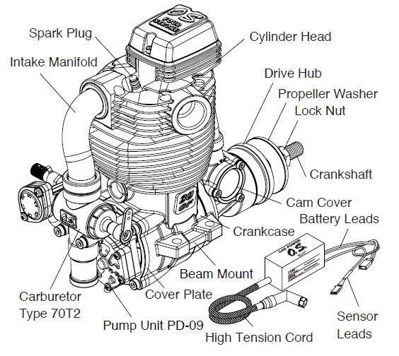
ENGINE PARTS NAME
INSTALLATION
- It is suggested to use as heavy and rigid as possible engine mounting for highest performance and safe running. Install the engine on a mount using at least 4mm steel screws, such as Allen type, with locknuts, for bolting the engine to the bearers.
- Also, use the Nord Lock Washers (optional extra) and other anti-loosening washers or apply locking agent.
- Be sure that there is sufficient air intake and outlet area on the model for engine cooling to avoid overheating. (Pay careful attention to the cooling since a gasoline engine generates more heat than a glow engine.)
INSTALLATION OF SPARK PLUG
Install the supplied spark plug firmly on the engine with O.S. Long Socket Wrench (optional: code no. 71521000), or with a commercially available 8mm deep socket wrench.
INSTALLING SILENCER
- Screw the exhaust manifold in the exhaust port of the cylinder head as far as possible and fix it with the lock nut. (Insufficient screwing in may result in damaging the screw threads of the exhaust port due to vibration.)
- Screw the silencer on the exhaust manifold within more than 10mm and less than 25mm range. Set the required outlet angle and fix it with the lock nut.
- It is suggested to apply locking agent to the screw threads to prevent loosening and also to make sure no loosening from time to time and retighten if necessary.
PCV VALVE
This engine is employed with PCV (Positive Crankcase Ventilation) valve.Ventilation in the crankcase is positively done with the change of pressure in the crankcase and one-way check valve. Blow-by gas and oil waste are returned to the combustion chamber via intake port.
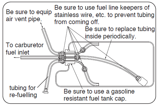
FUEL TANK & LINES
- Use a tank designed for gasoline. (Tanks designed for glow fuel use a rubber cap which is deteriorated by gasoline.)
- A 230cc tank will provide 10~15 minutes flight. (With full throttle, it will provide 7~8 minutes flight.)
- Install a commercially available gasoline fuel filter between fuel tank and carburetor. (Clean the filter from time to time.)
- For plumbing, use TYGON F-4040A tube (yellow color) or O.S. fluolorubber tube (I.D. 3mm, O.D. 5mm, 500mm length: code no. 28382200). Replace tubing periodically as it becomes hardened. (Replace tubing inside the fuel tank every six months.)
- Use fuel line keepers of stainless wire, etc. at the end of the tubing to prevent the tubing from coming off.
- This engine does not require a muffler pressurized fuel system but be sure to provide an air vent.
- Be sure to install a fine in-line fuel filter between the tank and carburetor to prevent foreign matter in the tank from entering the carburetor. Clean the filter periodically.
CARBURETOR PARTS NAME
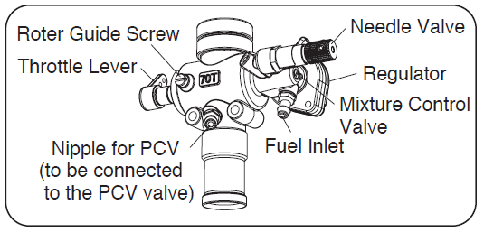
Two adjustable controls are provided on this carburetor.
- The Needle-ValveFor adjusting the mixture strength when the throttle is fully open Needle-valve adjustment effect the mixture strength at round mid speed.
- The Mixture Control ValveFor adjusting the mixture strength at part-throttle and idle speed, to obtain steady idling and smooth acceleration to mid speed.
Please note with this carburetor, needle-valve adjustment does not effect the mixture control valve adjustment but the mixture control valve adjustment effects the needle-valve adjustment. Therefore, it is required to adjust also the needle-valve when the mixture control valve is adjusted. Mixture control valve is pre-set at nearly best position when the engine leaves the factory. Therefore, it is not necessary to adjust the mixture control valve until running-in is completed.
CARE OF FUEL PUMP & REGULATOR
- NEVER disassemble the fuel pump or pressure regulator. Their original performance may not be restored after reassembly.
- DO NOT allow foreign matter to enter the fuel system. Dirt inside the pump or regulator, no matter how small, may obstruct the flow of fuel and prevent these components from working properly
- NEVER insert anything into the inlet or outlet nipples in an attempt to clear a suspected obstruction.
- DO NOT obstruct the small rectangular hole at the bottom of the regulator, nor the regulator will not function correctly.

- ALWAYS use fuel filters. Keep the fuel tank scrupulously clean and filter all fuel as it enters the tank (e.g.via an O.S.’Super-Filter’ Code No.72403050) and use a good quality in-line filter between the tank and pump. Remember to inspect filter screens at regular intervals and rinse clean as necessary.
- NEVER use kerosene, thinner or any organic solvent for cleansing the pump. Rubber parts will be ruined by these materials. Use only alcohol (methanol) or gasoline.
THROTTLE LINKAGE
Before connecting the throttle to its servo, make sure that the throttle arm and linkage safely clear any adjacent part of the airframe structure, etc., as the throttle is opened and closed. Connect the linkage so that the throttle is fully closed when the transmitter throttle stick and its trim lever are at their lowest settings and fully open when the throttle stick is in its fully-open position. Carefully align the appropriate holes in the throttle arm and servo horn so that they move symmetrically and smoothly through their full travel.
IGNITION MODULE
Major specifications
- Consumption current is 400mA/6,000rpm/6V. Use a power source of more than 1000mAh capacity.
- The ignition module is set not to operate below 120rpm for safety.
- The voltage of power source is 4.8~8.4V (rated).(Ni-Cd, Ni-MH 4~6 cells, Li-Po, Li-Fe 2 cells)
Installation
- Install the ignition module taking sufficient anti vibration measures.
- Install the ignition module at least 100mm away from the engine and in a place where there is airflow so that engine exhaust heat and radiation heat may not affect its operation.
- Do not share the power source with receiver and use a separate power source.
- Equip an ON/OFF switch between the ignition module and its power source, and install it in a place where can be operated from outside the model.
- Install the ignition module and its power source as far as possible away from the servos and receiver power source.
- Connect the sensor leads of the igniter module (white, red black three parallel wires) to the sensor leads from the engine.
- Connect the battery leads of the ignition module (red, black two parallel wires) to the power source.
- Make sure the jackets of high tension cord do not touch the engine and cowl to avoid accidental short circuit.
- Make sure to connect the plug cap onto the spark plug not to come off.
Precautions
- Do not disassemble the ignition module and plug cap. (The ignition module is irreparable. Replace it when necessary.)
- Be careful not to mount the ignition module so that it can be hit by water, gasoline or exhaust.
- Avoid using the engine when the external temperature is over 40 C.
- Do not move the rpm sensor as it is placed at it’s optimum position, otherwise the engine will not run properly.
- Hold the plug cap and pull it out to disconnect from the spark plug. Be careful not to damage your fingers while removing it.
- Do not connect nor disconnect the rpm sensor with the ignition module on, or there is a possibility it will fire and the engine start.
- Check the ignition module for spark when installing the plug cap on the plug and be careful about getting a shock. Make sure there is no flammable material or gasoline vapors near by that could ignite.
- Do not turn the propeller with the ignition module on, or there is a possibility the engine will start
PROPELLER
The choice of propeller depends on the design and weight of the aircraft and on the type of flying in which you will be engaged. Determine the best size and type after practical experimentation. As starting point, refer to the props listed in the table shown below. Slightly larger, or even slightly smaller props than those shown in the table may be used, but remember that propeller noise will increase if blade tip velocity is raised due to high rpm or if a larger diameter/lower pitch prop is used. Be well aware propeller rotating arc is very large due to a large propeller used with this engine. Carry out adjustments of the needle valve and mixture control valve after stopping The engine. Do not allow your face or hands to come close to the rotating prop.
Type: Sport / Acro / ScaleSize (DxP): 16×10-12, 17×8-10, 18×6W-8
Warning: Make sure that the propeller is well balanced.An unbalanced propeller and/or spinner can cause serious vibration which may weaken parts of the airframe or affect the safety of the radio-control system. Do not use any propeller which has become split, cracked or nicked even very slightly, or received strong impact even if no apparent damage is visible.
PROPELLER & SPINNER ATTACHMENT
There is a risk, particularly with powerful four-stroke engines, of the propeller flying off if the prop nut loosens due to detonation (“knocking”) in the combustion chamber when the engine is operated too lean, or under an excessively heavy load.Obviously, this can be very hazardous. To eliminate such dangers, the O.S. Safety Locknut Assembly was devised.
Install this as follows:
- Install the propeller to the engine shaft, followed by retaining washer and propeller nut and tighten firmly with a 14mm wrench (not supplied).
- Add the special tapered and slotted locknut and secure with a 12mm wrench (not supplied) while holding the propeller nut with the 14mm wrench.
Note:Some spinners which are retained at the top of the cone cannot be used with the propeller locknut supplied with the engine. In this case, optional locknut sets are available from O.S. – Propeller Locknut Set for Spinner (Code No.45910200 4mm) and (Code No.45913000 5mm).
NOTE:
Make a habit of always checking the tightness of the propeller before starting the engine. Remember that, especially with wooden propellers, there is a tendency for the material to shrink, or for it to be reduced by the serrated face of the drive hub. Retighten the propeller nut if necessary after loosening the Safety Propeller Locknut. The locknut should be tightened firmly after retightening the propeller nut.
FUEL
- Use regular gasoline. (No need to use high octane gasoline.)
- Alcohol based glow fuel cannot be used in this engine. Not only will the engine not work properly but the internal carburetor plastic parts will be damaged.
- Use high quality commercially available 2 stroke engine oil.
- Follow the oil manufacturer’s recommendations concerning the mixture ratio of gasoline and oil. If there is no recommendation, mix with a 30:1 ratio. We have checked and approved the following oil mixture ratio. Zenoah genuine 2 stroke engine oil (50:1) and KLOTZ ModelLube (50:1). (This does not mean we guarantee the quality of these oils.) Follow the instructions in the running-in section concerning the mixture for running-in.
- With a gasoline engine, passages in the carburetor are narrower than that of a glow engine, and therefore very sensitive against foreign matter such as dust. It is suggested to use optional accessory Super Filter L (Code No. 72403050) when filling a tank in the model from a container used for transportation or storing.
RUNNING-IN
- Use a fuel with increased oil content and set the needle a little on the rich side. Too rich a needle setting may cause misfiring or erratic running due to fouling of the plug.
- Use a 25:1 fuel/oil mixture if the particular brand of oil states 50:1 mix. Use a 20:1 fuel/oil mixture if the particular brand of oil states 25:1 mix. Set only the needle valve 200 below maximum rpm. The mixture control valve need not be richened.
- No need to carry out running-in on a bench nor with the model fixed. Just fly the model with the above mentioned fuel and needle setting.
- A total of 10 flights (2 litters fuel) are required. Avoid prolonged full throttle running at initial stage, and gradually extend the full throttle running time.
WARNING:When ground running the engine, avoid dusty or sandy locations. If dust or grit is drawn into the engine, this can have a ruinous effect, drastically shortening engine life in a matter of minutes.
STARTING
- The GF30 cannot be started by flipping a propeller. Be use to use an electric starter to start the engine.
- The GF30 is not equipped with a choke valve. Draw the fuel to the carburetor by an electric starter.
- Open the needle-valve 2.5 to 3 turns from the fully closed position. (Mixture control valve is pre-set at nearly best position when the engine leaves the factory.Therefore, do not adjust the mixture control valve at this point.)
- Turn the transmitter switch ON.
- Turn the receiver switch ON.
- Turn the igniter switch OFF.
- Set the throttle at half opened position.
- Draw the fuel to the carburetor by turning the engine for 7 to 8 seconds with an electric starter.
- Set the throttle at 1/8 open from the fully closed position.
- Turn the igniter switch ON.
- Tell the helper and onlookers that you will start the engine now and have the helper hold the model securely.
- Apply an electric starter to start the engine.
CARBURETOR ADJUSTMENT
1. Before attempting to operate your engine
Although the carburetor’s appearance and construction resemble conventional glow engine’s carburetor, how to adjust is completely different from that for glow engine‘s carburetor. Please study the following instructions so as to familiarize yourself with the controls and other features of the engine.
- It is expected the engine runs a little unstably (uneven RPM and light breathing) until the inside parts of the carburetor get used to the fuel (around when the running-in is completed) but the engine won’t quit. Run the engine as it is. Also, for about 10 seconds after the first starting of the day, it is expected the engine runs unstably but the engine won’t quit. Run the engine as it is.
2. Key points for adjustments
- Mixture control valve is pre-set at nearly best position when the engine leaves the factory. Therefore, it is not necessary to adjust the mixture control valve until running-in is completed.Adjust the needle-valve only.
- With a conventional glow engine, the needle-valve is gradually closed from the rich mixture. On the contrary, with the GF30, the needle-valve is opened from the lean mixture. Please fully note this difference.
3. Adjustments
1) Needle-valve adjustment
- Open the throttle fully gradually when the engine is started.
- Close the needle-valve and the engine RPM increase. (Close the needle-valve at a pace of 30~45 degrees/second smoothly.)
- When the needle-valve is closed further, engine RPM stop increasing and then RPM start decreasing. Close the needle-valve 60 to 90 degrees further from the point where RPM start decreasing.
- Then, open the needle-valve rather slowly (at a pace of 15 degrees/second) and the engine RPM increase.
- Open the needle-valve 60-90 degrees further from the point where maximum RPM are obtained. This is the nearly best needle-valve position. Fly the model with this needle-valve position until running-in is completed (10 full tank or 2 liters flights). Please observe the general precautions during running-in such as to avoid prolonged full throttle running and increase load gradually.
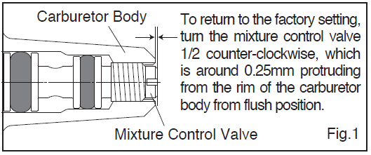
2) Mixture control valve adjustment
- Make sure the mixture control valve is at the factory setting. (see Fig.1)
- After starting the engine, open the throttle fully for 5 to 6 seconds to warm up the engine, and adjust the main needle as previously shown.
- Set the idling at around 2,000 rpm with the throttle trim on the transmitter.
- Move the throttle stick from the idling to the fully open position several times repeatedly, and measure the idling rpm with a tachometer. In case idling is unstable and the rpm decrease gradually in 20 seconds at the idling position, the mixture control valve is set rich. On the other hand, the mixture control valve is set lean if the rpm increases at the idling position, or the engine doesn’t respond quickly to reduce the rpm at around 2,000 rpm when the throttle stick is moved from the fully open position to the idling position.
- Stop the engine. If the adjustment is rich, turn the mixture control valve clockwise 30 degrees at maximum per each adjustment. If the adjustment is lean, turn the mixture control valve counter-clockwise. Each adjustment should be within 30 degree needle turn.
- Repeat the procedures 2 – 5 until the idling rpm becomes stable. After deciding the mixture control valve adjustment, determine the final main needle adjustment.
- Set the idling rpm with the throttle trim on the transmitter at the optimal position depending on the propeller size and the airplane model.
- The engine is almost ideally adjusted if the engine accelerates smoothly from idling to full throttle even you move the throttle stick quicker and slower.
- Move the throttle stick quickly to full throttle. In case the engine hesitates before picking up speed or even ceases firing, the mixture control valve is set lean. Stop the engine and open the mixture control valve 15 degrees counter-clockwise.
- Move the throttle stick slowly to fully throttle. In case the engine responds sluggishly to increase rpm, or the idling rpm is unstable, the mixture control valve is set rich. Stop the engine and close the mixture control valve 15 degrees.
- Whenever the mixture control valve is readjusted, the main needle should be readjusted.
Hereafter adjust the needle-valve and/or mixture control valve if required according to the flight conditions. Please note with this carburetor, needle-valve adjustment does not effect the mixture control valve adjustment but the mixture control valve adjustment effects the needle-valve adjustment. Therefore, it is required to adjust also the needle-valve when the mixture control valve is adjusted.
REALIGNMENT OF MIXTURE CONTROL VALVE
In the course of making carburetor adjustments, it is just possible that the Mixture Control Valve may be inadvertently screwed in or out too far and thereby moved beyond its effective adjustment range.
NoteGenerally, a gasoline engine is sensitive to a lean mixture compared with a glow engine, and will stop without warning hesitation and stops with overheating. It is recommended that the engine be run with a slightly richer mixture.
VALVE ADJUSTING
Valve clearances are correctly set before any O.S. engine leaves the factory and, in normal use, will seldom require adjustment. However, if, after a considerable amount of running time, a loss of power is detected, or if he engine has been disassembled for repair, these clearances should be checked and reset as necessary. Clearance should be 0.04mm – 0.1mm (.0015″ – .004″) For checking and adjusting the valve clearances, a VALVE ADJUSTING TOOL KIT is available as an optional accessory.
Also, a 5.5mm wrench (not supplied) is required for this purpose.
- Wrench 5.5mm
The kit comes in a plastic case and includes: (Code No.72200060)
- Feeler gauge 0.04mm
- Feeler gauge 0.1mm
- Hex. key 1.5mm
- Wrench 5mm
FLIGHT & MAINTENANCE
Checking prior to flight
- When the engine is started, make sure the radio control system works normally (distance test).
- Engine does not run erratic with full throttle.
- Idling is stable.
- Responds positively to the throttle operation.
- Warm-up is finished.
Warm-up is required as with full size aircraft and car engines. Take off the model after warming the engine for approx. 10 seconds with full throttle.
Precautions in flight
- A slight engine rpm increase and decrease delay is normal. Abrupt throttle operation will the cause engine to quit. Move throttle smoothly.Cooling is more vitally important to a gasoline engine than to a glow engine. If overheating symptoms (loss of power at full throttle or exhaust note at mid speed changes from cloudy one to clear one) are observed during flight, immediately stop flying and carry out the following countermeasures.
- Enlarge the air intake cutout on the cowling.
- Enlarge the air outlet cutout on the cowling. (It is vitally important.)
- Partly cover the air intake cutout on the cowling where air does not hit direct the engine.
- Install an air guiding plate on the fuselage and cowling so that cooling air may be guided to the cylinder portion of the engine and muffler.
When the interval between the flights is short and the engine is still hot, it may be possible overheating symptoms are observed by circulating the head from the former flight through the engine even if the overheating symptoms were not observed during the former flight. In this case, leave it until the engine is fully cooled down (in hot weather, it may take more than one hour.) or run the engine for 4 to 5 minutes at idle.
Maintenance after the day’s flights
Please pay attention to the matter described below to ensure that your engine serves you well in regard to performance, reliability and long life.
- Check the tightening of each screw, especially engine installation screws and silencer installation screws each time. Also, for the first several flights, tighten the screws after each flight.
- As previously mentioned, it is vitally important to avoid operating the engine in conditions where dust, distributed by the propeller, may be deposited on the engine and enter its working parts.
- Remember to keep your fuel container closed to prevent foreign matter from contaminating the fuel.
- Install a fuel filter to prevent foreign matter in the fuel container from entering the fuel tank. O.S. Super Filter (L) is available as an optional extra.
- Install an in-line fuel filter between the tank and carburetor to prevent foreign matter in the tank from entering the carburetor.
- Clean these filters periodically.
- If these precautions are neglected, restrictions of fuel flow may cause the engine to cut out, or the fuel/air mixture to become too lean causing the engine to overheat.
- With a gasoline engine rust hardly occurs. Check the exterior to make sure there is nothing wrong and wipe off any oil res.
- Fill the carburetor with fuel at the conclusion of a day’s flying. (Pay careful attention to fire and ignition source when carrying and storing the model.)
- If the engine is stored without filling the carburetor, with fuel the inside parts will dry out and not work properly at the next running. If the engine quits out of fuel, refill the carburetor with fuel.
- When the engine is not to be used for a long period (more than a year), remove the engine from the model, clean the outside then remove the carburetor, and plug all tubing. Clean inside the engine by rotating the crankshaft with the engine immersed in container filled with gasoline.
- Also use gasoline to clean the outside of the carburetor. Clean the outside only because the inside parts are sensitive to foreign substances.
O.S. GENUINE PARTS & ACCESSORIES
- RADIAL MOUNT SET GF30/GF3011(71904400)
- PROPELLER LOCKNUT SET FOR SPINNER5/16″-M4 (45910200); 5/16″-M5 (45910300)
- LOCK WASHER (10sets)M5 (55500004)
- SUPER FILTER (For Fuel Container)(S) (72403051(L) (72403050)
- NON-BUBBLE WEIGHT (S) )(For Fuel Tank) (71531010)
- VALVE ADJUSTING TOOL KIT(72200060)
- LONG SOCKET WRENCH WITH PLUG GRIP(71521000)
- FLUORORUBBER TUBEID. 2mm x OD. 4mm Length 500mm (28382100)ID. 3mm x OD. 5mm Length 500mm (28382200)
CARBURETOR EXPLODED VIEW & PARTS LIST

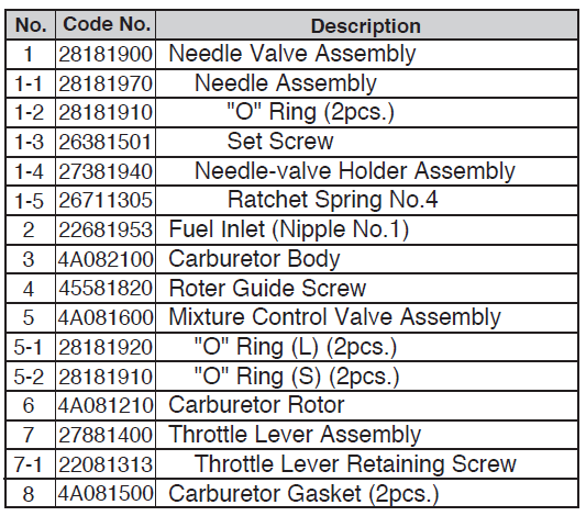
The specifications are subject to alteration for improvement without notice
ENGINE EXPLODED VIEW & PARTS LIST

CAP SCREW SETS(10pcs./sets

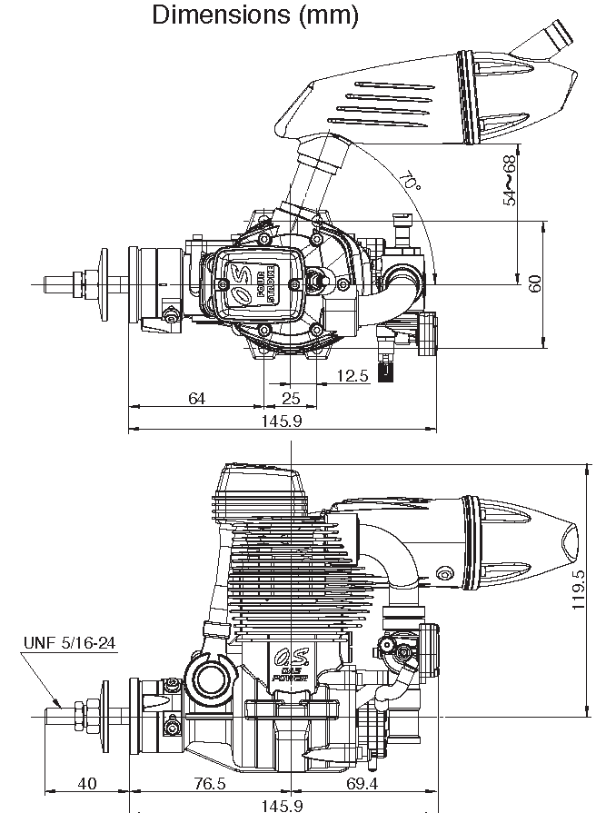
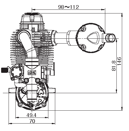
THREE VIEW DRAWING
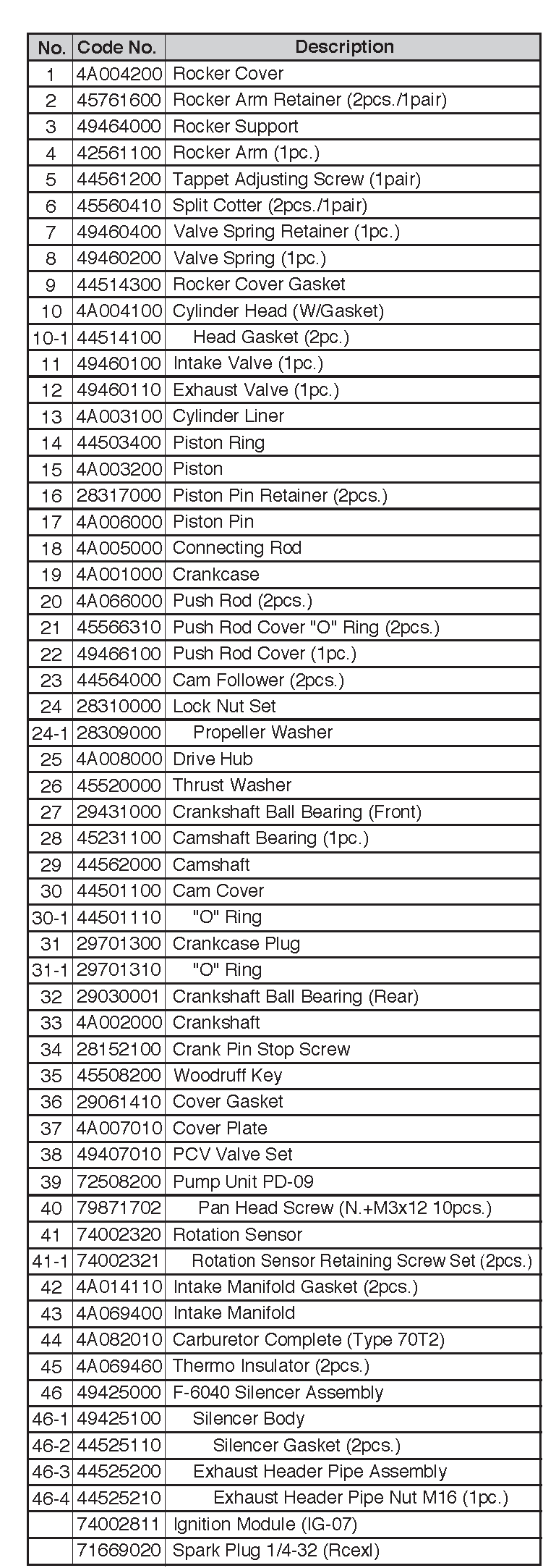
※ We put 1 piece of gasket in the cylinder head as the factory setting although we sell 2 pieces as spare parts (#4451410
SPECIFICATIONS

6-15 3-Chome Imagawa Higashisumiyoshi-kuOsaka 546-0003, Japan T E L . ( 0 6 ) 6702-0225FAX. (06) 6704-2722
References
[xyz-ips snippet=”download-snippet”]