![]()
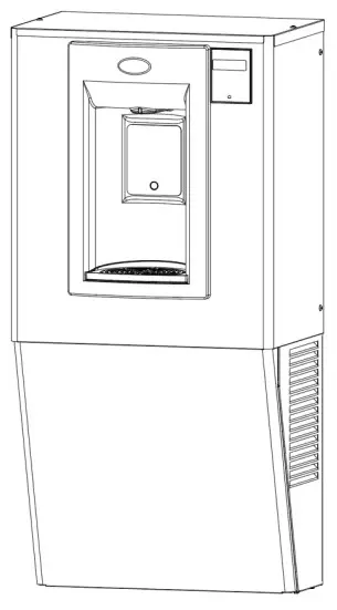
PGN8EBFWall Mounted Refrigerated Bottle Filler
INSTALLATION INSTRUCTIONS
Section 1: Getting Started
What’s Included:

Tools & Hardware Required:
- Electric drill/driver
- Small tubing cutter for plastic line
- 1/4″ nut driver
- Means to cut 1-1/4” drain pipe
- T15 Torx screwdriver and bit
- 4 appropriate anchors (not supplied)
Section 2: Single Level Rough-In Drawing
PGN8EBF:
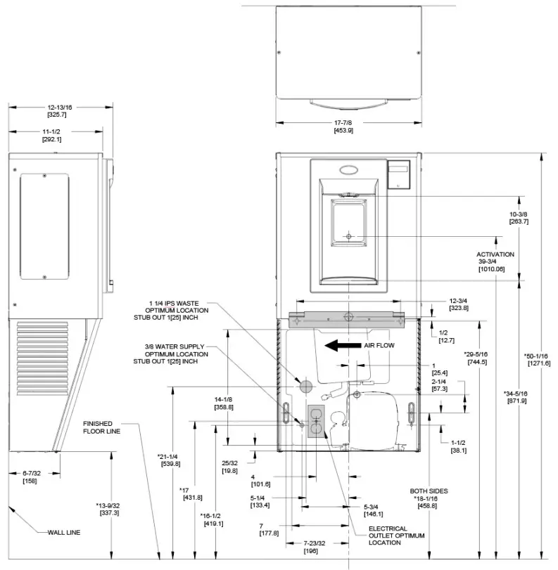
NOTES:
- TRAP, STOP VALVE, AND ELECTRICAL OUTLET NOT FURNISHED.
- ALLOW 4 INCHES [102MM] MIN. PER SIDE FOR VENTILATION.
- RECOMMENDED ADULT BARRIER-FREE HEIGHT INSTALLATION SHOWN. REDUCE HEIGHT BY 3 INCHES FOR INSTALLATIONS USED PRIMARILY BY CHILDREN AGES 12 AND YOUNGER.UNIT SHALL ALSO HAVE A MINIMUM CLEAR FLOOR SPACE 30[760] BY 48[1220]. ADJUST VERTICAL DIMENSIONS AS REQ’D TO COMPLY WITH FEDERAL, STATE, AND LOCAL CODES.
- ALL DIMENSIONS ARE IN INCHES. DIMENSIONS IN BRACKETS [ ] ARE IN MILLIMETERS.
Section 3: Preparation
Read these instructions before installing the unit.
- Inspect the carton and water cooler for evidence of rough handling and concealed damage. Damage claims should be filed with the carrier.
- Locate and install plumbing and electrical service, if required, in accordance with Roughing-in Drawing. See page 3.Note: The following states require a licensed plumber to install a cooler; AR, GA, MA, ME, OK, RI, SC, SD, TX, VT, and WI. CA, KS, MN, NM, and OR allow for a state-registered installer or contractor as well. State and local plumbing codes may prohibit the use of saddle tapping valves for water line connection in some applications. All connections must conform to applicable plumbing codes.

- This drinking water cooler is designed to be operated at a water supply line pressure of up to 100 psi (690 kPa). A pressure regulator must be installed in front of the unit’s water inlet if water pressure (including any possible pressure spikes) could exceed 100 psi (690 kPa).
- Check available power supply against the water cooler data plate to assure correct electrical service. This drinking water cooler is intended to be connected to a 20A minimum ground fault circuit interrupting (GFCI) device to meet UL requirements. The rearmost 1-3/8” diameter knockout in frame bottom is for an externally located electrical supply. Make sure the knockout hole edge is smooth and free of any burrs. Use of Heyco bushing #2184 in the knocked-out hole is recommended in order to prevent damage to the service cord and to close up excess opening around the cord. Route cord so it does not interfere with ADA space requirements.

CHILLER INSTALLATION
Section 4: Chiller Installation
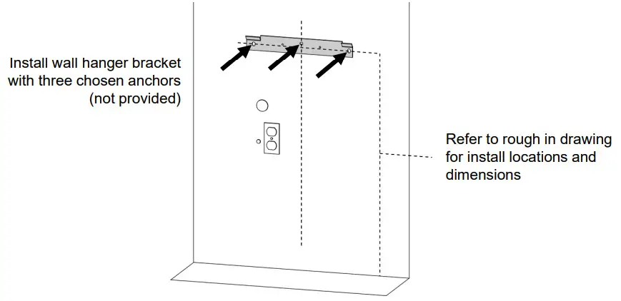
- Install the wall hanger onto the wall according to the rough-in drawing. See page 3.The Wall hanger is shipped fastened to the back of the chiller unit.
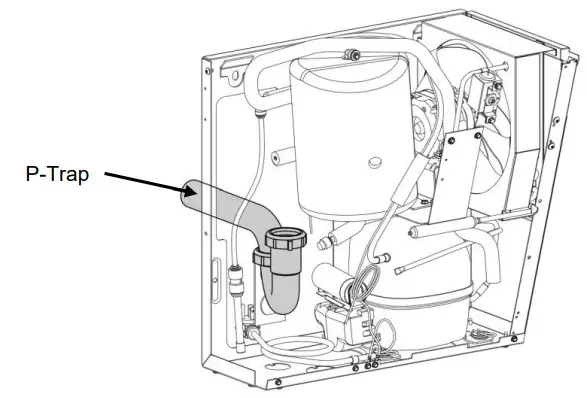
- Once the chiller unit is hung on the wall, Install a p-trap in the waste line and a shut-off valve in the water supply line.
- An in-line strainer is furnished in a “Water Supply” tube. Connect the “Water Supply” tube to the shut-off valve. |NOTE: This connection should not be a solder joint or flare connection to allow access to the strainer for service. Using one of the 1-3/4” diameter knockouts for a waste line is not recommended because of a potential conflict with ADA toe space clearance requirements. Check your local building code inspector for approval.
- Rotate the fan blade by hand to see that it is free of obstructions.
- Leave the front panel off for the Bottle Filler installation.
BOTTLE FILLER INSTALLATION
Section 4: Installation
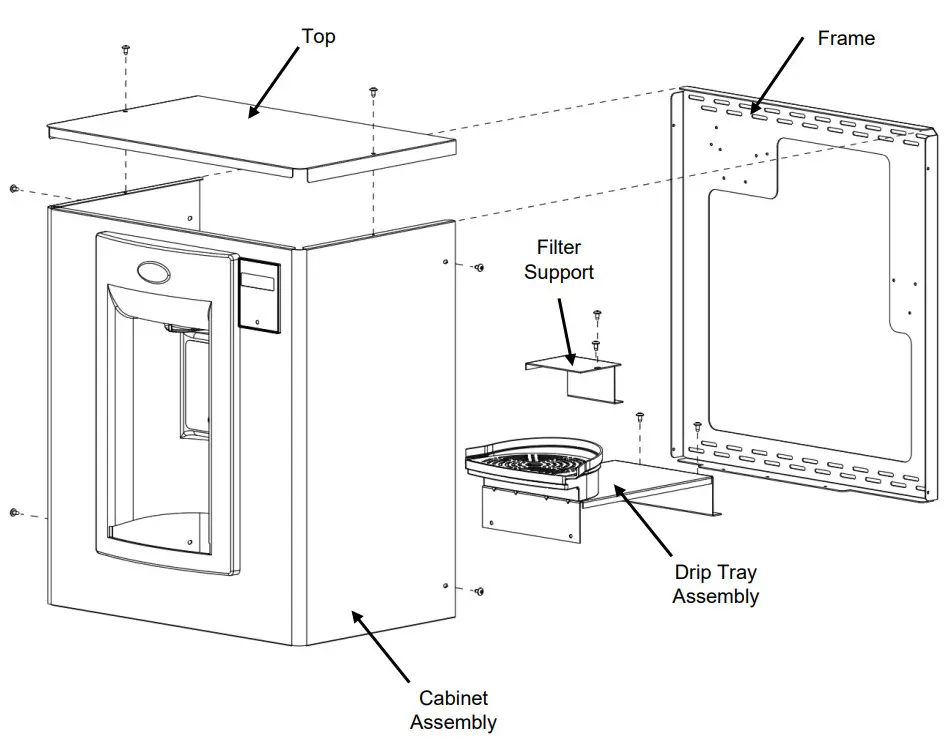
- The PGN8EBF comes partially assembled for shipping. Remove the kit from thepackaging and separate it into the assemblies and components shown below.Tool Needed: T15 Torx bitSection 4: Installation
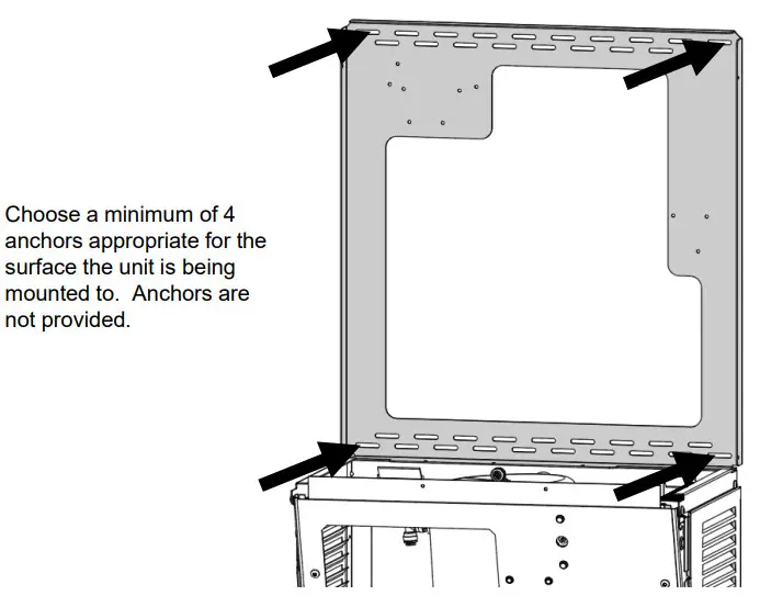
- Place the bottle filler frame against the wall and set it onto the top flange of the chiller frame.
- Affix the frame to the wall with at least 4 anchors into any appropriate anchor points through the staggered slotted holes. Be careful to ensure the frame stays centered on the cooler frame.Section 4: Installation
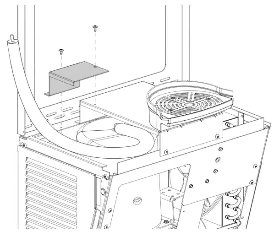
- With 4x T15 Torx screws, assemble the drip tray assembly to the center bracket and wall frame.
- Attach the filter support bracket with 2x T15 Torx screws to the frame and drip tray support bracket. This bracket helps to prevent the filter cartridge from falling into the cooler unit below during installation or replacement.Section 4: Installation
- Attach one of the drain elbows to the drip tray stem. Insert the drainpipe provided into the elbow and then attach another elbow onto the pipe. Use the remaining drainpipe and connect the drip tray drainage system to the installed P-trap.NOTE: Drainpipes will need to be positioned and cut to length as needed.
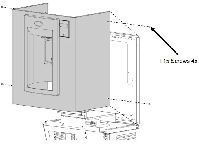
- Assemble the PGN8EBF wrapper to the installed frame. Rest the alcove on the drip tray and ensure the wrapper walls rest OUTSIDE of the frame and side brackets.NOTE: The drip tray will hold the weight of the wrapper but it is recommended to keep a hold on the unit during installation for safety.Section 4: Installation
- If the outer edge of the drip tray is not properly aligned, loosen the screws mounting the filter support and drip tray bracket to the frame, and push forward or back as needed. Then retighten the screws.Section 4: Installation
- Route the insulated cold water-out line up into the bottle filler cabinet and connect it to the solenoid valve located above the alcove.
- Connect the IEC connector to the power brick located behind the alcove of the bottle filler. It is recommended to route the power cord from the side opposite of the condenser fan to ensure it does not become an obstruction.Section 4: Installation
- Complete the installation by turning on the water source and checking for leaks.
- Ensure nothing is obstructing the fan blade. Plug the power cord back into the wall outlet and then test to ensure the bottle filler is functioning properly.
- Once the unit has been verified to be functioning properly, install the front cover panel by inserting the top flanch up between the wrapper and center bracket, then tipping the panel back to the fountain. Secure it with the 2x #8 hex screws at the base of the unit.
- Complete the installation by installing the Bottle Filler top and filter Access Panels.
 Section 4: Installation
 Section 4: Installation
 Section 4: Installation
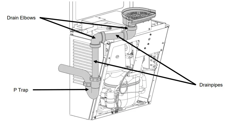
 Section 4: Installation
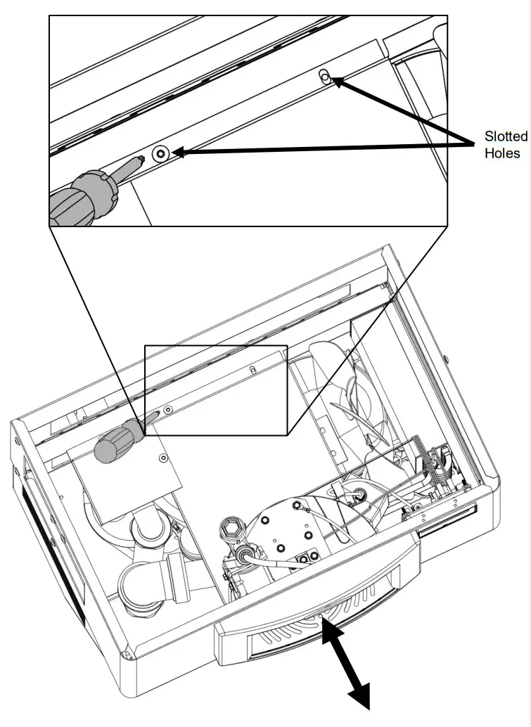 Section 4: Installation
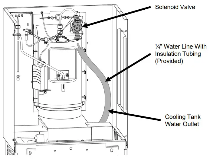
 Section 4: Installation
Section 5: Set-Up Guide For OASIS® Hands-Free Bottle Filler Electronics
Factory default program settings are:
- Units – Gallons
- Unfiltered unit
- Flow Meter = Rate Selected
- Filter Capacity = 1250 gallons [4731 liters]
- Bottle Count = 0.5L (1 Bottle)
- Flow Rate = 1.2 GPM
- 20 second maximum dispense time
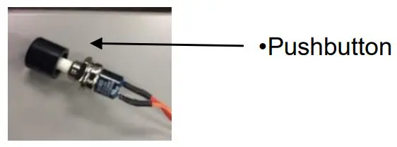
For each model top cap will need to be set aside until programming is complete. Remove top cap by unscrewing two (2) T15 Torx screws if needed. Remove wire tie bundling pushbutton inside bottle filler and feed it through a hole in the cooler top. You can then adjust the program using a pushbutton through the access panel of the cooler.
| Display | Action |
| 000000000 BOTTLES REUSED (Home Screen) | Depress button for 3 seconds to enter into the following menu settings and make changes. Note: at any time it will exit the menu and save settings when idle for 10 seconds (no button press) and revert back to Home Screen. |
| LTR/GAL GAL | Depress button 3 seconds to change from Gallons to Liters, or momentary press to advance to next menu. |
| UNFILT/FILT?UNFILT UNIT | Depress button 3 seconds to change from Unfiltered to Filtered unit, or momentary press to advance to next menu. |
| FLOWMETER?RATE SELECTED | Depress button 3 seconds to change from Rate Selected to (Flow) Meter Enabled, or momentary press to advance to next menu. |
| SELECT RATE1.2 GPM UNIT | To change the flow rate, momentarily depress the button to change the whole gallon digit. Hold button 3 seconds to advance to TENTHS of gallon digit.Depress momentarily to change the digit.Hold the button for 3 seconds to advance to the next menu. |
| RESET 00000000 GALLON CNT[LTR COUNT] | Depress button for 3 seconds to reset Gallon or Liter count, or momentary press to advance to next menu. |
| FILT CAPAC OF 1250 GAL [4731 LTR] | Depress button for 3 seconds to change filter capacity to 3000 GAL [11355 liters] for Galaxi green filter,
or momentary press to advance to the next menu. |
| 3 sec rule? 0.5L | Depress button for 3 seconds to switch from 0.5L bottle to 3-sec rule, or momentary press to advance to next menu.
(The 3 Sec rule increases the bottle count based on a 3-second dispense.) |
| Reset 00000000BOT COUNT? | Depress button for 3 seconds to reset (Home Screen) BOTTLES REUSED count, or momentary press to advance to next menu. |
| Bot Filler Set time: 20 s | Depress button for 3 seconds to change maximum dispense time to 10, 20, or 30 seconds, or momentary press to advance to next menu. |
| RUN CAL AGAIN? | Depress button 3 seconds to run the calibration again, or momentary press to advance to the next menu. |
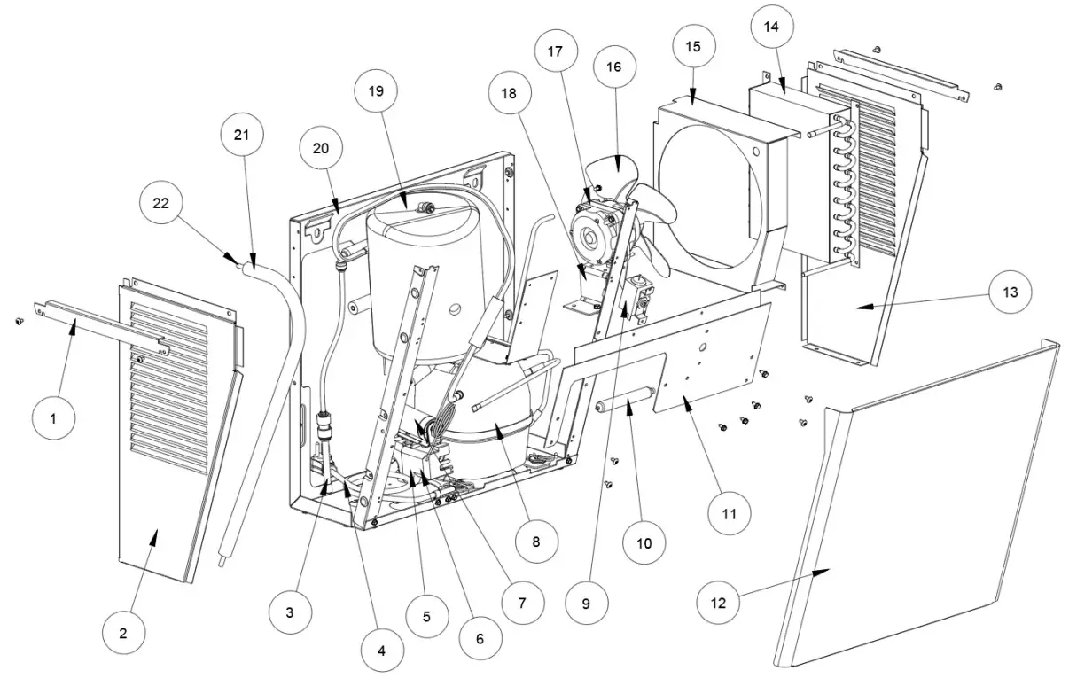
Section 6: Bottle Filler Parts Breakdown

|
ITEM |
QTY | P/N |
DESCRIPTION |
| 1 | 1 | 041245-002 | Frame |
| 2 | 1 | 041241-001 | The panel, NN Filter |
| 3 | 1 | 041238-002 | Wrapper |
| 4 | 2 | 031875-003 | Screw, Truss HD Tapping |
| 5 | 2 | A020967 | 1 1/2″ Elbow, W/Nuts, 1 1/4″ |
| 6 | 1 | 036010-002 | Waste, Tube |
| 7 | 1 | 036010-013 | Waste, Tube |
| 8 | 1 | 041244-002 | Bracket, Drip Tray |
| 9 | 1 | 041246-002 | Bracket, Filter Support |
| 10 | 1 | 036192-001 | Drain, MSBF Short |
| 11 | 1 | 036192-001 | Grille, Bottle Filler Drain |
| 12 | 3 | 026675-003 | Screw, Flat HD Tapping |
| 13 | 1 | 038031-006 | Label, Alcove Sensor |
| 14 | 1 | 038031-005 | Label, LCD Bezel |
| 15 | 1 | 038036-003 | Power Supply, 100240VAC/12VDC |
| 16 | 1 | 036190-003 | Alcove, EBF |
| 17 | 1 | 038032-001 | Flow Nozzle |
| 18 | 1 | 028668-101 | FTG, PP Reducing Union |
| 19 | 1 | 030152-009-SP | Tube, PE White 7.5″ |
| 20 | 1 | 038030-002 | Solenoid Valve 12VDC |
| 21 | 1 | 031434-014 | Nameplate, OASIS |
| 22 | 1 | 026824-026 | Nut, Hex Nylon |
| 23 | 1 | 041243-002 | Panel, Top |
| 24 | 1 | 038026-002 | Electronics ASSY, IR/LCD |
| 25 | 1 | 038027-001 | Lens, IR Bottle Filler |
Section 7: Chiller Parts Breakdown
|
ITEM |
QTY | P/N |
DESCRIPTION |
| 1 | 2 | 041242-002 | Bracket, ONN Side |
| 2 | 1 | 035080-010 | The panel, Side Left STN 430 |
| 3 | 1 | 026794-014 | Tube, Straight |
| 4 | 1 | 026407-027 | Elec CKT DWG W/Lead Wire P/NS |
| 5 | 1 | 041234-001 | Relay-PTC |
| 6 | 1 | 041235-001 | Overload |
| 7 | 1 | 041336-001 | Capacitor, Start 88-108UF |
| 8 | 1 | 041233-001 | Compressor Assy THK4430YAA |
| 9 | 1 | 027040-039 | Control, Cold |
| 10 | 1 | 034343-003 | Drier W/O Process Port |
| 11 | 1 | 041243-002 | Bracket, ONN Center |
| 12 | 1 | 041250-001 | The panel, ONN Front |
| 13 | 1 | 035081-010 | The panel, Side Right STN 430 |
| 14 | 1 | 031766-201 | Condenser |
| 15 | 1 | 031767-004 | Shroud, Fan |
| 16 | 1 | 038773-002 | Blade, Fan |
| 17 | 1 | 038813-001 | Motor, Fan |
| 18 | 1 | 036748-001 | Bracket, Fan Motor |
| 19 | 1 | 033469-063 | Tank Assy, Insul |
| 20 | 1 | 035089-001 | Frame, Back/Bottom SA |
| 21 | 1 | 017681-044 | Insulation, Sponge Tube 26″ |
| 22 | 1 | 030152-097 | Tube, PE Cut Length WHI 27″ |
Section 8: Maintenance and Decommissioning
Maintenance
- Inspection of the condenser should be made at 3-month intervals. To remove dirt and lintfrom the condenser, disconnect the power supply cord, then use a small stiff non-wire or vacuum cleaner attachment brush. Observance of this procedure will ensure adequate air circulation through the condenser so operation is efficient and economical.
- Outside of the unit can be wiped clean with mild soap and water mixture. Never use harsh chemicals or abrasive cleaners, including any chlorine solutions. Rinse thoroughly with clean water, then dry surfaces.
Overload Protection
The compressor motor, where used, is equipped with an automatic reset protector which will disconnect the motor from the line in case of an overload.
Lubrication
This unit is equipped with a hermetically sealed compressor and requires no additional lubrication. The fan motor, where used, on this unit seldom needs oiling, but if required, a few drops of SAE 10 oil should be used.
 report this ad
To Discontinue use of Water Cooler
- Close the water shut-off valve and disconnect power to the CHILLER.
- Provide a container to catch water to be drained and place it under the cold tank drain.
- Remove the drain plug from the drain tube.
- Actuate the bottle filler and allow the water to drain into the bucket. Replace the drain plug.
- Disconnect power to the BOTTLE FILLER.
- Disconnect the water supply line at the shut-off valve.
WARNING
The warranty and the Underwriters’ Laboratory Listing for this machine are automatically voided if this machine is altered, modified, or combined with any other machine or device. Alteration or modification of this machine may cause serious flooding and/or hazardous electrical shock or fire.
EXCEPT AS SET FORTH HEREIN, THE MANUFACTURER MAKES NO OTHER WARRANTY, GUARANTEE OR AGREEMENT EXPRESSED, IMPLIED, OR STATUTORY, INCLUDING ANY IMPLIED WARRANTY OR MERCHANTABILITY OR FITNESS FOR A PARTICULAR PURPOSE.
Wall Mounted Refrigerated Bottle FillerInstallation InstructionsP/N 030099-670 Date: 05/2021© 2021 LVD Acquisition, LLCOasis is a registered trademark of LVD Acquisition, LLC dba
![]() Oasis InternationalOASIS INTERNATIONAL222 East Campus View Blvd.Columbus, OH 43235614-861-1350www.oasiscoolers.com
Oasis InternationalOASIS INTERNATIONAL222 East Campus View Blvd.Columbus, OH 43235614-861-1350www.oasiscoolers.com
References
[xyz-ips snippet=”download-snippet”]