omega Gas Cooktop
CONGRATULATIONSWelcome to the Omega Kitchen Community and thank you for choosing one of our many fantastic cooking appliances. We are confident that you will now be able to meet your cooking needs. Before you use the cooktop we strongly recommend that you read though the whole user manual which provides the description of this product and the proper use of its functions.To avoid the ever-present risks involved with using an electrical appliance it is vital that the appliance is installed correctly by an authorized person and that you read the safety instructions carefully to avoid misuse and hazards.It is important that you retain these instructions and your proof of purchase along with any other important documents about this product for future reference. Due to continual product development, Omega reserves the right to alter specifications or appearances without notice.
Before operating your appliance for the first time, take care that the appliance has been correctly installed into a fixed workbench, that all electrical and gas connections have been completed, that all removable parts (trivets, burner parts etc) are in position and any transit protection has been removed.
IMPORTANT SAFETY INSTRUCTIONS
IMPORTANT: Read the assembly instruction section and safety precautions of this booklet carefully before removing the contents of this carton.
- This appliance is not intended for use by persons (including children) with reduced physical, sensory or mental capabilities, or lack of experience or knowledge, unless they have been given supervision or instruction concerning the use of the appliance by a person responsible for their safety. Children should be supervised to insure that they do not play with the appliance.
- In certain circumstances electrical appliances may be a safety hazard. The unit MUST be connected to the electrical supply before operation to enable the electronic ignition to work.
- Do not place heavy objects on this appliance.
- Damage can occur to bench tops if pots and pans are able to overlap the bench top. This can result in heat being transferred to the bench top. Ensure that correct sized pots & pans are used. Refer to guide in booklet.
- Do not allow pot handles or utensils to be placed near gas burners which are operating, as they can cause the handles to become hot to touch. Always turn handles away when small children are nearby. It is recommended that children are kept away from the cooktop at all times.
- If the electrical supply cord is damaged, either when being installed or after installation, it must be replaced by the manufacturer, it’s service agent or similarly qualified persons in order to prevent a hazard.
- The electrical and gas connections must be accessible after installation.
- Electrical connection must be made as per local wiring rules and regulations.
- Ensure that the kitchen is well ventilated or mechanical ventilation is in use while cooking on the gas cooktop.
- DO NOT USE OR STORE FLAMMABLE MATERIALS IN THE APPLIANCE STORAGE DRAWER OR NEAR THIS APPLIANCE. DO NOT SPRAY AEROSOLS IN THE VICINITY OF THIS APPLIANCE WHILE IT IS IN OPERATION.
- WARNING – The cooktop will become hot during and directly after use. Do not touch any components during this time, as they may be hot and can cause burns.
- Cleaning may only be commenced on the appliance once it has cooled down.
- When the appliance is not being used, the knobs must be kept in the ‘OFF’ position.
- Not to be used in a marine environment.
- DO NOT USE THIS APPLIANCE AS A SPACE HEATER.
- DO NOT MODIFY THIS APPLIANCE. This appliance is not suitable for use with aftermarket lids or covers.
 DO NOT OPERATE THIS APPLIANCE BEFORE READING THE INSTRUCTION BOOKLET.DO NOT PLACE ARTICLES ON OR AGAINST THIS APPLIANCE.DO NOT STORE CHEMICALS OR FLAMMABLE MATERIALS OR SPRAY AEROSOLS NEAR THIS APPLIANCE.DO NOT USE EXTERNAL CONTROLLERS OR TIMERS ON THIS APPLIANCE DO NOT OPERATE THIS APPLIANCE BEFORE READING THE INSTRUCTION BOOKLET.DO NOT PLACE ARTICLES ON OR AGAINST THIS APPLIANCE.DO NOT STORE CHEMICALS OR FLAMMABLE MATERIALS OR SPRAY AEROSOLS NEAR THIS APPLIANCE.DO NOT USE EXTERNAL CONTROLLERS OR TIMERS ON THIS APPLIANCE |
SUPPLIED WITH THIS APPLIANCE
| PARTS: | QUANTITY: |
| USER MANUAL | 1 PC |
| SEALING TAPE | 1 ROLL |
| ADDITIONAL LABELS | 1 SET |
| INSTALLATION CLIPS | 4 SETS |
| INSTALLATION SCREWS | 4 PCS |
| ULPG INJECTORS | 1 SET (5 PCS) |
| INLET ELBOW | 1 PC |
| WASHERS | 3 PCS |
| NG REGULATOR | 1PC |
APPLIANCE DETAILS
|
Gas Type: |
ULPG |
NG |
||
|
Burner Pressure: |
2.75 kPa |
1.00 kPa |
||
|
Injector Diameter |
MJ/hr Rating | Injector Diameter |
MJ/hr Rating |
|
|
Auxiliary Burner |
Ø0.55 mm | 4.0 MJ/ hr | Ø0.90 mm |
4.0 MJ/ hr |
|
Semi-Rapid Burner |
Ø0.70 mm | 6.3 MJ/ hr | Ø1.10 mm |
6.0 MJ/ hr |
|
Rapid Burner |
Ø0.90 mm | 10.0 MJ/ hr | Ø1.40 mm |
10.0 MJ/ hr |
|
Wok Burner |
Ø0.98 mm | 13.0 MJ/ hr | Ø1.70 mm |
13.0 MJ/ hr |
Note: The size of the injector diameter is stamped on the front face (e.g. 1.8 for Ø1.80mm injector).
|
Relevant Sizes: |
LENGTH (mm) | WIDTH (mm) |
HEIGHT (mm) |
|
Hob size |
860 | 500 |
90mm |
|
Cut-out size |
827 | 470 |
– |
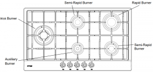
Table of recommended pot sizes for each burner type:
|
BURNER TYPE |
NG: DIAMETER OF POT (mm) |
ULPG: DIAMETER OF POT (mm) |
|
Auxiliary Burner |
Ø80 TO Ø195 |
Ø80 TO Ø195 |
|
Semi-Rapid Burners |
Ø140 TO Ø195 |
Ø140 TO Ø195 |
|
Rapid Burner |
Ø160 TO Ø220 |
Ø160 TO Ø200 |
|
Wok Burner |
Ø195 TO Ø270 |
Ø195 TO Ø230 |
| Electrical: |
Value: |
| Input Voltage: |
220V to 240V @ 50Hz to 60Hz |
| Maximum Current: |
0.5A |
GAS CONNECTIONS
LOCAL AUTHORITY REQUIREMENTS
Check Gas Type and specifications plate placed on the bottom face of the unit. All gas fitting work, service and repairs can only be performed by an authorized person in accordance with the current edition of AS/NZS5601 and local gas regulations. Failure to comply with this condition will render the warranty invalid.Always unplug the appliance before carrying out any maintenance operations or repairs. The walls of the units must not be higher than work top and must be capable of resisting temperatures of 75 above temperature. Do not install the appliance near flammable materials (eg. curtains). The final act of any installation or gas type conversion must be the full testing of this appliance, which includes leak testing, ignition of each burner and the functionality of the burners separately and together.
INSTALLATIONThe appliance is predisposed and adjusted to operate with the gas indicated on the specifications plate (normally NG) applied onto the appliance. Please see gas rates summary information on the previous page. If the appliance must be operated with a gas different than that indicated on the plate, it is necessary to execute the following operations:
- Gas connection including regulator (NG) or test point nipple adaptor (LPG) to be changed.
- Replacement of the injectors.
- New gas label attached stating gas type.
- Adjustment of minimum setting.
GAS CONNECTIONThe connection must be made by a qualified gas fitter according to the relevant standard. The gas connection is positioned 40mm from the left hand side (from front), 30mm in from the back edge. The fitting (fig. 6.1) is made up of: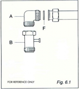 1 elbow fitting “A”1 gaskets “F”1 ULPG test point nipple adaptor “B”The hob must be installed in a room with adequate ventilation (see installation section).
N.G.:Fit the supplied NG regulator to the elbow fitting “A” using two spanners (note orientation of the NG regulator gas flow). Connect the other side of the NG regulator to the gas inlet pipe with the correct ½” BSPT thread connector using two spanners.
U.L.P.G.:Connect the ULPG test point nipple adaptor “B” to the cooking hob inlet “A” and then connect to the gas inlet pipe with the correct ½” BSPT thread connector (or using the appropriate adaptor) using two spanners. Connect the other end of the pipe to the cylinder pressure regulator.
ORIENTATION OF THE ELBOWThe appliance is supplied with a gas connection oriented towards the centre of the cooking hob. The connection to the gas supply must be effected only from this side or in vertical position by turning the elbow downwards. To turn the elbow, first loosen the nut. Adjust the position of the elbow to the final position and retighten the nut. Make sure that there are no leakages by testing with a soapy solution and brush.
IMPORTANT: Never attempt to turn the elbow “A” without having first slackened off the relative lock nipple. The seal “F” (fig. 6.1) seals the gas connection. It is recommended that it be replaced when it begins to show even the slightest deformation or imperfection. After connecting to the gas supply, check that the couplings are correctly sealed, using soapy solution and a brush, but never a naked flame. Where a flexible hose assembly is used, ensure it is approved to AS/NZS 1869, Class B Ø10mm, and no longer than 1m. Any hose assembly must be restrained from accidental contact with the flue outlet of an under-bench oven.
OPERATIONS TO BE PERFORMED WHEN CONVERTING GAS TYPESThis operation can only be performed by an authorized person. Remove the gratings and the burner covers;Using a spanner, replace the nozzle injectors “J” (Fig.20) with either Natural Gas sized injectors or LPG sized injectors.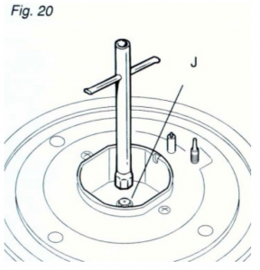
REGULATING THE BURNER MINIMUM SETTINGWhen switching from one type of gas to another, the minimum flow rate must also be correct. The flame should not go out even when passing suddenly from maximum to minimum flame. To regulate the flame follow the instructions below:Light the burnerSet the gas valve to minimum
On gas valves provided with adjustment screw in the centre of the shaft (fig.21) Using a screwdriver with max. diameter 3mm, turn the screw inside the tap until the correct setting is obtained.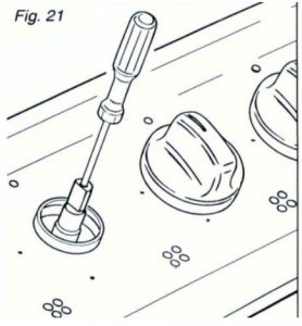 On gas valves provided with adjustment screw on the valve body (fig.22):Turn the screw “A” to the correct setting with a screwdriver.
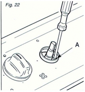
LUBRICATION OF THE GAS TAPSThis can only be performed by an authorised person. It may be required if the gas taps become stiff and difficult to turn.
LEAK TESTING
- Make sure gas control knobs are Off and turn the cylinder valve On.
- Check for leaking joints by brushing with solution of half-liquid detergent and half water. If a leak is present, bubbles will appear (or you may hear a hissing sound). Retightening connections can generally repair a leaking joint. You must also check the gas hose and connection at the gas cylinder. If a leak cannot be resolved, do not proceed.
 DO NOT USE NAKED FLAME FOR LOCATING GAS LEAKS. IF A LEAK PERSISTS CALL AN AUTHORISED GAS FITTER.
Ensure the appliance is fully tested after cooktop installation is complete.
NOTE: If an appliance cannot be adjusted to perform correctly, contact your nearest service department.
ELECTRICAL CONNECTIONS
LOCAL AUTHORITY REQUIREMENTSInstallation is only permitted by an authorized person, and carried out according to instructions provided by the manufacturer. Incorrect installation might cause harm and damage which the manufacturer accepts no responsibility. The electrical connection can be found 30mm in from the rear edge and 280mm from the left hand side (looking from the front).
INSTALLATIONThis cooktop must be connected to a 220-240V 50Hz power supply. It is earthed via the cord.Before carrying out the connection to the power supply, the voltage rating of the appliance (stamped on the appliance identification plate) must be checked for correspondence to the available mains supply voltage, and the mains electric wiring should be capable of handling the hob’s power rating (also indicated on the identification plate);The power point must be connected to a suitable earth wiring, in conformity to current safety regulations.Ensure that the power supply is within 900mm of the cooktop. The power supply cord must not touch against any hot surfaces and must be placed so that its temperature does not exceed 75 degrees C at any point along its length.The colours of the wires in the hob power cable may not correspond with the colours marked on the terminals of your electrical plug .The plug should in any case be wired as follows:
- connect the green/yellow wire to the terminal marked with the letter E or the earth symbol or coloured green/yellow;
- connect the blue wire to the terminal marked with the letter N or coloured black;
- connect the brown wire to the terminal marked with the letter L or coloured red.
After having installed the appliance, the power switch or power plug must always be in an accessible position.
Electrical connection diagram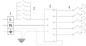
N.B For connections to the mains power supply, never use adapters, reductions or multiple power points as these may overheat and catch fire.In the event that installation should require modifications to the mains supply wiring system or if the power plug is not suitable for the type of power point available, it is required that a qualified technician be called to carry out substitution.The technician will also have to verify that the cross-section of the electric cables on the power point match the appliance’s power rating
INSTALLATION
Note: These tops are designed to be fitted into kitchen fixtures measuring 600 mm in depth. In order to install the cooker top into the kitchen fixture, a hole with the dimensions shown on the cutting size board has to be made, keeping in consideration the following: Within the fixture, between the bottom side of the cooker top and the upper surface of any other appliance or internal shelf there must be a clearance of at least 30 mm; Keep at least 200mm from the periphery of the burners to any side or rear wall with combustible surfaces or keep the appliance sides at least 50mm from walls with non-combustible surfaces. There must be a distance of at least 650 mm between the hob and any extractor hood or wall cupboard positioned immediately above it. The distance to an overhead exhaust fan must be at least 750mm. The duplicate data plate should be fixed in an accessible position close to the appliance (inside face of cupboard door, side of cabinet etc). Note: Keep a safe distance away from combustible constructions. After installation, all burners should be tested individually and together to ensure correct operation.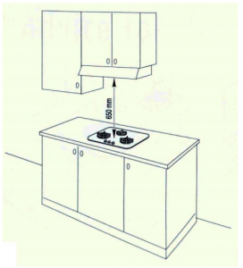
INSTALLATION IN KITCHEN CABINET WITH DOORThe fixture has to be made according to specific requirements in order to prevent the gas burners from going out, even when the flame is turned down to minimum, due to pressure changes while opening or closing the cupboard doors.When the hob is installed above a cupboard with doors, a separate panel must be installed underneath it. Leave a gap of at least 30 mm clearance between the cooker top and the surface of the panel (fig.13), which must be easily removable to allow sufficient access for any servicing procedures. NOTE: When installing above a cupboard, a dividing shelf (as above) must be installed. If installed above an under bench oven, this is not required. Installation of an oven without a cooking fan underneath the hob is forbidden.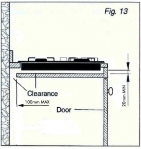
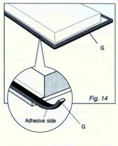
PREPARING & PLACING THE HOB FOR INSTALLATION Every cooker top is provided with a set of tabs for fitting to the unit with thickness from 3 to 4 cm and a seal with adhesive on one side.
- Remove burners and grids.
- Turn the cooker top over and rest the top face on a cloth.
- Apply the self-adhesive seal “G” as illustrated in (fig.14).

- Slot the cooker top into the unit and position.
- Position the cooker top in the recess and secure by means of the brackets as shown in fig.15 (for 3 or 4 cm thick work top).

DISCHARGING PRODUCTS OF COMBUSTIONExtractor hoods connected directly to the outside must be provided, to allow the products of combustion of the gas appliance to be discharged (fig.16).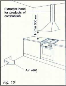 If this is not possible, an electric fan may be used, attached to the external wall or the ceiling above the cooktop. The fan should have a capacity to circulate air at an hourly rate of 3-5 times the total volume of the kitchen (fig.17).
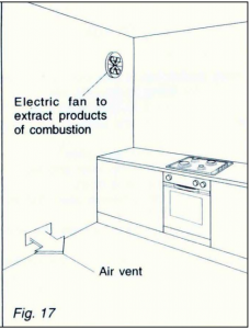
OPERATING INSTRUCTIONS
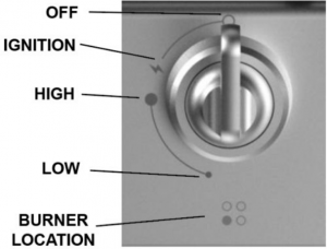
IGNITING THE BURNERSThe knob on your gas cooktop controls both ignition and the safety device. Proceed as follows to ignite the burners:Press down & turn the knob for the burner you would like to use. Keep the knob strongly pressed in for approximately 1 second to allow the ignitor to light the gas, and allow the thermocouple to heat up. Release the knob after approximately 1 second. The flame can be adjusted by turning the knob anti clockwise until it reaches the desired size. Only turn the knob between the High and Low settings, otherwise the burner will turn off.To turn off the burner, push down & rotate the knob around to the `Off’ position. Note: If the burner does not light within 12-15 seconds, turn the control knob back to the `Off’ position, and attempt re-ignition after 1 minute. This will allow any unburned gas to escape from the burner area. If the burner does not light, firstly check that the cooktop is connected to electricity.If connected ensure that the gas is turned on and that the electrodes are sparking. Also ensure that all burner caps are placed correctly on the burner rings.
USING THE BURNERSFor greater efficiency and less gas consumption, use pots and pans with the right diameters for the burners. Avoid having flames extending out from underneath the pans (refer to the table in the appliance details section for recommended sizing). When cooking, always try to use a pot or pan with a flat base. Pots & pans with an uneven or curved base will cause the burner to run inefficiently and will take longer to cook your food. Always heat the water to boiling point before placing food items to be cooked. After the water has boiled, the heat setting can be dropped to maintain the desired cooking temperature. This will speed up the cooking time and is more efficient. In the event of a power outage, your gas cooktop can still be used. Press & turn the desired knob to the `High’ position and light with a match. Depress the knob after approx. 3 seconds and continue to operate the burner.Large utensils exceeding the recommended size can cause excessive heat to reflect back onto the appliance, potentially damaging the appliance and causing a temperature hazard.
AUTOMATIC SAFETY VALVESThis safety device automatically closes the gas valve if there is any disruption of the gas flow to the appliance, or if the gas flame goes out.
CLEANING & STORAGE
CLEANINGPlease follow the maintenance & cleaning guidelines below to keep your Omega cooktop in good working order.The cooktop should be cleaned regularly with all stains and boil overs being cleaned up. Do not allow stains and boil overs to become burnt onto the appliance.Please ensure the cooktop is cold when cleaning, to avoid burns from hot components.Try to minimize the use of specialized cleaning products. Attempt to clean with soapy water and a sponge. If this is not successful, a mild cleaner can be used.Do not use abrasive cleaners or scourer type pads to clean the appliance. These can damage the Stainless Steel finish.A stainless steel cleaner can be applied which gives the cooktop an extra shine. Only apply after cleaning with soapy water.Avoid leaving acidic or alkaline substances on the cooktop.Burners and enameled components are only to be washed with soapy water & sponges. Do not use abrasive cleaners on these components.When cleaning burner components, please ensure that they are fully dry before re-placing on the cooktop and before use.Ensure that all components are placed back onto the cooktop correctly. Failure to do so can cause problems with the burners igniting and functioning correctly. See diagrams on the following page for how to put the burners back together.
WOK BURNER MAINTENANCE & ASSEMBLY
When fitting the wok burner together, it is very important to check that the burner flame distributor (F) and the cap (C) are correctly positioned (fig. 6). Failure to do so can cause problems with ignition and also the way in which the burner operates.Check that the electrode (S) is always clean to ensure trouble-free sparking.Check that the probe (T) is always clean to ensure correct operation of the safety valves (for models with safety device).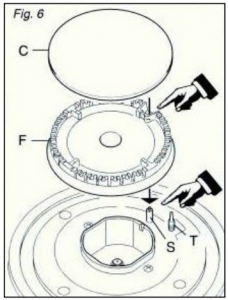 The Wok burner must be correctly positioned (see fig.7).
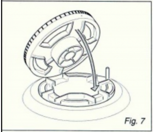 The burner rib must lock into position on the assembly below. If positioned correctly, the burner will not rotate (fig.8).Then position the enamel cap A and the enamel ring B (fig.8).
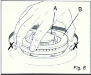 The four holes around the outside of the crown must always be kept clean.When cleaning, remove the flame divider (fig.9) and use a cotton bud, toothbrush, or a stiff wire brush to clean out any incrustations or dirt from the four holes marked “H” (fig.10).
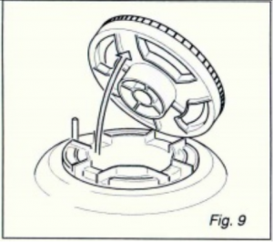
 This procedure is necessary to ensure the burner functions correctly
MAINTENANCE
Clean burner tops and trivets at least once a week, or after any spillage. Check injectors are not blocked and the electrode and probe are clean.Gas inlet pipes should be checked periodically for leakages (see section on leak testing) a minimum of every 12 months.Lubrication of gas valves – This can only be performed by an authorised person. It may be required if the gas tap become stiff and difficult to turn.
|
Fault |
Possible cause (corrective action) |
| No spark / No ignition of gas | Power outage, appliance power turned off at isolation switch, fuse blown / tripped, no gas to the appliance (check supplies). Spillage of liquid over burner (clean up spillage on burner components). Burner not assembled correctly (Refer to assembly instruction manual). |
| Burner ignites but flame goes out when control knobs released. | Control knob not depressed down enough when igniting burner, control knob being released from the ignition mode too early (try ignition again). Spillage of liquid over burner (clean up spillage on burner components). Burner not assembled correctly (Refer to assembly instruction manual). Faulty thermocouple (technician call out required call Service Centre). |
| Erratic / Abnormal flames or noise when operating the appliance. | Burner not assembled correctly (Refer to assembly instructions). Spillage of liquid over burner (Clean up spillage on burner components). Oversize cooking vessel being used on the appliance (use smaller cooking vessels). Internal ignition of burner (Turn off gas and reignite burner). Wrong gas type being used (check supply and data labels) |
AUSTRALIAN AND NEW ZEALAND PRODUCT WARRANTY STATEMENT OF STANDARD WARRANTY CONDITIONS
AUSTRALIAN CUSTOMERSOur goods come with guarantees that cannot be excluded under the Australian Consumer Law. You are entitled to a replacement or refund for a major failure and for compensation for any other reasonably foreseeable loss or damage. You are also entitled to have the goods repaired or replaced if the goods fail to be of acceptable quality and the failure does not amount to a major failure.
NEW ZEALAND CUSTOMERSNothing herein contained shall be construed in any way as excluding or limiting your rights under the Consumer Guarantee Act 1993.
OUR WARRANTYThis product is also covered by the manufacturer’s warranty set out in this document (Our Warranty).Our Warranty is for a period of twenty four (24) months from the date of purchase. This is in addition to (and does not exclude, restrict or modify) any rights or remedies to which you may already be entitled to under the Australian consumer law or the New Zealand Consumer Guarantee act 1993 relating to this product. Our warranty (which is subject to the conditions below) covers rectification free of charge of any fault arising from defective materials or components or faulty workmanship. The product will be repaired or replaced at the option of Omega
Our warranty is subject to the following conditions:
- That the purchaser contact Omega prior to any product repair.
- That the purchaser carefully follows all instructions provided with the product and complies with all relevant electrical & plumbing regulations in their State when installing the product.
- That the purchaser carefully follows the instructions provided in the owner’s handbook relating to the proper use and care of the product and does not use the product for any purpose other than the DOMESTIC use for which it has been designed. If the appliance is used in commercial applications or for rental purposes, Our Warranty is limited to a warranty of Twelve (12) months covering all parts with Three (3) months on any labour cost of service or repair.
WHAT IS COVERED: By Our Warranty
During the warranty period, Omega or its authorised Service Centre will, at no extra charge, if your appliance is readily accessible without the need of special equipment and subject to the terms and conditions of this warranty, repair or replace any parts which it considers defective.
WHAT IS NOT COVERED: By Our Warranty
- Products installed damaged or incomplete or not in compliance with the relevant electrical & plumbing regulations in their State.
- Normal wear and tear e.g. cleaning, light globes, filters etc.
- Failure resulting from power surges and electrical storms.
- Insect or vermin infestation.
- Unauthorized repairs or use of non- genuine Omega parts.
- Any failure caused by the product not being used in accordance with the instruction and the installation manual provided with the product.
- Misuse or abuse, including failure to properly maintain or service.
- The clearing of blockages in pumps and hoses.
- Damage which occurs during delivery or installation.
- Claims to product surface coating due to liquid or solid spill-overs, accidental damage or damage caused from cleaning products not recommended by Omega.
HOW TO CLAIM YOUR WARRANTYPlease refer to our website address below for Omega in Australia or New Zealand to register your warranty online.If you are contacting Omega regarding any warranty claims and spare parts inquiries, please make sure you have the following information on hand:
- Product Name/Model Number
- Serial Number/s
- Purchase Date (as per invoice or proof of purchase)
- Purchased From
- Warranty Registration Number
Thank you for introducing our family to yours
At Omega, we understand that cooking, cleaning and washing may not be your favourite things in the world. That’s why we created a range of no-nonsense, reliable products that always get the job done for you. With the features you need and nothing you don’t. What’s more, they’re made to fit perfectly into your home life and your wallet. You are welcoming an Omega appliance into your place and you can be sure it’ll always serve you well.
We aim to simplify any further appliance purchases. When researching our products you will find a range of icons that visually represent our products key features. Visit our website to learn more about these icons and the features and benefits of our products.
For important information such as instruction manuals, specifications and catalogues, please visit omegaappliances.com.au/customer (for Australia) or omegaappliances.co.nz/customer (for New Zealand). Also, make sure you activate your product warranty by registering your warranty online using the links above.
We value your opinion, so please take a few minutes to tell us what you think about your new addition! Simply go to the relevant appliance page of our website omegaappliances.com.au and click on “Write a Review”.
If you want to know more about promotions, receive cool tips and tailor made content or just connect with us on social media, like omega appliances on Facebook and follow omegaappliances_aus on Instagram.
Enjoy your new appliance and remember, we’re only one click away!
 omegaappliances.com.au / omegaappliances.co.nz
 omegaappliances
 omegaappliances_aus
IN AUSTRALIAwww.omegaappliances.com.au/customer/warrantyOmega is division of Shriro Australia PTY LTDABN 28 002 386 129Customer care: 1300 739 033Email: [email protected]
IN NEW ZEALANDwww.omegaappliances.co.nz/customerOmega is division of Monaco Corporation Limited(Member of Shriro Australia PTY LTD)Phone: (09) 415 6000Email: [email protected]

References
[xyz-ips snippet=”download-snippet”]