
Omega OCG64XTGG 60cm 4 Burner Gas Cooktop Instruction Manual
OCG64XTGGOCG64FFETGGOCG604XCOMOCG604FFECOMOCG604X
Thank you for purchasing an Omega appliance
Tailored for the modern aesthetic and lifestyle of busy people, your new Omega Appliance will make a welcome addition to the family.
Omega caters to style-savvy customers who look for balance between stunning form and clever function. This means a combination of sleek, chic, sophisticated design yet effortless functionality.And we source from the best. The best craftsmanship. The best innovation. From the best international design-houses.
All brought together under an appliance that stands for design-led balance.
Please take the time to read through the following instruction manual to familiarise yourself with the installation, operation requirements and maintenance to ensure optimum performance.
Further Information
For important information about your Omega Appliance such as warranty registration, manuals, features, and specifications please visit omegaappliances.com.au (if you are in Australia) and omegaappliances.co.nz (if you are in New Zealand) or contact our Customer Care team on the below email or phone numbers.
Registering Your Warranty
For peace of mind you can register your warranty at omegaappliances.com.au. Further information on the Warranty can be found at the end of this manual.
Contact Us
Our customer service team is here to help you with any question or concern.Both teams are on call Monday to Friday 8.30am to 5.00pm and of course you can always send an email at your convenience.
Australia Contact DetailsMonday to Friday 8.30am – 5.00pmEmail: [email protected]Phone: 1300 739 033
New Zealand Contact DetailsMonday to Friday 8.30am – 5.00pmEmail: [email protected]Phone: 09 415 6000
To stay up to date and find simple and easy recipes, follow us on our socials:facebook.com/omegaappliancesinstagram.com/omegaappliances_aus
READ THE INSTRUCTION BOOKLET BEFORE INSTALLING AND USING THE APPLIANCE.
It is important that you retain these instructions, proof of purchase as well as other important documents about this product for future reference.The manufacturer will not be responsible for any damage to property or to persons caused by incorrect installation or improper use of the appliance.
Due to continual product development, Omega reserves the right to alter specifications and appearances without notice.
Disposal Information
- Most of the packaging materials are recyclable. Please dispose of these materials through your local recycling depot or by placing them into appropriate collection containers.
- If you wish to discard this product, please contact your local authorities and ask for the correct method of disposal.
Important Safety Warnings
IMPORTANT: Read the assembly instruction section and safety precautions of this booklet carefully before removing the contents of this carton.
- This appliance is not intended for use by persons (including children) with reduced physical, sensory or mental capabilities, or lack of experience or knowledge, unless they have been given supervision or instruction concerning the use of the appliance by a person responsible for their safety. Children should be supervised to insure that they do not play with the appliance.
- In certain circumstances electrical appliances may be a safety hazard. The unit MUST be connected to the electrical supply before operation to enable the electronic ignition to work.
- Do not place heavy objects on this appliance.
- Damage can occur to bench tops if pots and pans are able to overlap the bench top. This can result in heat being transferred to the bench top. Ensure that correct sized pots & pans are used. Refer to guide in booklet.
- Do not allow pot handles or utensils to be placed near gas burners which are operating, as they can cause the handles to become hot to touch. Always turn handles away when small children are nearby. It is recommended that children are kept away from the cooktop at all times.
- If the electrical supply cord is damaged, either when being installed or after installation, it must be replaced by the manufacturer, it’s service agent or similarly qualified persons in order to prevent a hazard.
- The electrical and gas connections must be accessible after installation.
- Electrical connection must be made as per local wiring rules and regulations.
- Ensure that the kitchen is well ventilated or mechanical ventilation is in use while cooking on the gas cooktop.
- DO NOT USE OR STORE FLAMMABLE MATERIALS IN THE APPLIANCE STORAGE DRAWER OR NEAR THIS APPLIANCE. DO NOT SPRAY AEROSOLS IN THE VICINITY OF THIS APPLIANCE WHILE IT IS IN OPERATION.
- WARNING – The cooktop will become hot during and directly after use. Do not touch any components during this time, as they may be hot and can cause burns.
- Cleaning may only be commenced on the appliance once it has cooled down.
- When the appliance is not being used, the knobs must be kept in the ‘OFF’ position.
- Not suitable for use in marine craft, caravans or mobile homes.
- DO NOT USE THIS APPLIANCE AS A SPACE HEATER.
- DO NOT MODIFY THIS APPLIANCE. This appliance is not suitable for use with aftermarket lids or covers.
SUPPLIED WITH THIS APPLIANCE:
| PARTS: | QUANTITY: |
| USER MANUAL | 1 PC |
| SEALING TAPE | 1 ROLL |
| ADDITIONAL LABELS | 1 SET |
| INSTALLATION CLIPS | 4 SETS |
| INSTALLATION SCREWS | 4 PCS |
| ULPG INJECTORS | 1 SET (4 PCS) |
| INLET ELBOW | 1 PC |
| WASHERS | 3 PCS |
| NG REGULATOR | 1 PC |
Appliance Details
Note: The size of the injector diameter is stamped on the front face (e.g. 1.8 for Ø1.80mm injector).
Table of recommended pot sizes for each burner type:
Control Knob functions are displayed around each knob as shown below:
Gas Connections
LOCAL AUTHORITY REQUIREMENTS
Check Gas Type and specifications plate placed on the bottom face of the unit. All gas fitting work, service and repairs can only be performed by an authorized person in accordance with the current edition of AS/NZS5601 and local gas regulations. Failure to comply with this condition will render the warranty invalid. Always unplug the appliance before carrying out any maintenance operations or repairs. The walls of the units must not be higher than work top and must be capable of resisting temperatures of 75 above temperature. Do not install the appliance near flammable materials (eg. curtains). The final act of any installation or gas type conversion must be the full testing of this appliance, which includes leak testing, ignition of each burner and the functionality of the burners separately and together.
INSTALLATION
The appliance is predisposed and adjusted to operate with the gas indicated on the specifications plate (normally NG) applied onto the appliance. Please see gas rates summary information on the previous page. If the appliance must be operated with a gas different than that indicated on the plate, it is necessary to execute the following operations:
Gas connection including regulator (NG) or
- Replacement of the injectors.
- New gas label attached stating gas type.
- Adjustment of minimum setting.
GAS CONNECTION
The connection must be made by a qualified gas fitter according to the relevant standard. The gas connection is positioned 40mm from the left hand side (from front), 30mm in from the back edge. The fitting (fig. 2) is made up of: 1 elbow fitting “A”, 1 gaskets “F”
The hob must be installed in a room with adequate ventilation (see installation section).
N.G.:
Fit the supplied NG regulator to the elbow fitting “A” using two spanners (note orientation of the NG regulator gas flow).
Connect the other side of the NG regulator to the gas inlet pipe with the correct ½” BSPT thread connector using two spanners.
U.L.P.G.:
Connect to the gas inlet pipe with the correct ½” BSPT thread connector (or using the appropriate adaptor) using two spanners. Connect the other end of the pipe to the cylinder pressure regulator with appropriate LPG gas regulator.
ORIENTATION OF THE ELBOW
The appliance is supplied with a gas connection oriented towards the centre of the cooking hob. The connection to the gas supply must be effected only from this side or in vertical position by turning the elbow downwards. To turn the elbow, first loosen the nut. Adjust the position of the elbow to the final position and retighten the nut. Make sure that there are no leakages by testing with a soapy solution and brush.
IMPORTANT:
Never attempt to turn the elbow “A” without having first slackened off the relative lock nipple.The seal “F” (fig. 2) seals the gas connection. It is recommended that it be replaced when it begins to show even the slightest deformation or imperfection.After connecting to the gas supply, check that the couplings are correctly sealed, using soapy solution and a brush, but never a naked flame.Where a flexible hose assembly is used, ensure it is approved to AS/NZS 1869, Class B Ø10mm, and no longer than 1m. Any hose assembly must be restrained from accidental contact with the flue outlet of an under-bench oven.
OPERATIONS TO BE PERFORMED WHEN CONVERTING GAS TYPES
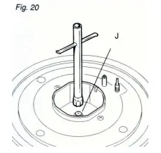 This operation can only be performed by an authorized person. Remove the gratings and the burner covers; Using a spanner, replace the nozzle injectors “J” (Fig.20) with either Natural Gas sized injectors or LPG sized injectors. Ensure you replace the corresponding gas type label on the appliance after conversion.
REGULATING THE BURNER MINIMUM SETTING
When switching from one type of gas to another, the minimum flow rate must also be correct. The flame should not go out even when passing suddenly from maximum to minimum flame. To regulate the flame follow the instructions below:
Light the burnerSet the gas valve to minimum
On gas valves provided with adjustment screw in the centre of the shaft (fig.21)Using a screwdriver with max. diameter 3mm, turn the screw inside the tap until the correct setting is obtained.
On gas valves provided with adjustment screw on the valve body (fig.22):
Turn the screw “A” to the correct setting with a screwdriver.
LUBRICATION OF THE GAS TAPS
This can only be performed by an authorised person. It may be required if the gas taps become stiff and difficult to turn.
LEAK TESTING
- Make sure gas control knobs are Off and turn the cylinder valve On.
- Check for leaking joints by brushing with solution of half-liquid detergent and half water. If a leak is present, bubbles will appear (or you may hear a hissing sound). Retightening connections can generally repair a leaking joint. You must also check the gas hose and connection at the gas cylinder. If a leak cannot be resolved, do not proceed.
Ensure the operation of the appliance is fully tested after cooktop installation is complete.
NOTE: If an appliance cannot be adjusted to perform correctly, contact your nearest service department.
Test And Adjusting Gas Pressure
NATURAL GAS – Appliance test point located at the regulator
The supplied regulator must be fitted to the appliance inlet connection. Gas pressure must be adjusted to 1.0 kPa when approximately 50% of the burners are on a high setting.
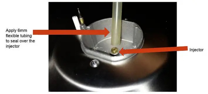
UNIVERSAL LPG – Appliance test point located at the burner injector
Gas pressure must be checked to confirm the appliance operating pressure is 2.75 kPa, the appliance test point is the rapid burner injector as shown below.
- Disconnect power
- Manually light the auxiliary burner and set to high flame
- Zero manometer, then apply flexible tubing to seal over the rapid burner injector, hold securely in place and check the gas pressure by pressing in the corresponding burner control knob on high flame position.
- If the pressure is 2.75 kPa, reassemble the burner and perform the final checks as per this instruction manual.
- If the pressure is not 2.75 kPa, disconnect the appliance and check/adjust/replace the LPG cylinder regulator(s) in accordance with AS/NZS 5601.
If the appliance is supplied with an LPG test point adaptor, then this component may be fitted to the inlet connection for the purpose of a test point
Electrical Connections
LOCAL AUTHORITY REQUIREMENTS
Installation is only permitted by an authorized person, and carried out according to instructions provided by the manufacturer. Incorrect installation might cause harm and damage which the manufacturer accepts no responsibility. The electrical connection can be found 30mm in from the rear edge and 280mm from the left hand side (looking from the front).
INSTALLATION
This cooktop must be connected to a 220-240V 50Hz power supply. It is earthed via the cord.Before carrying out the connection to the power supply, the voltage rating of the appliance (stamped on the appliance identification plate) must be checked for correspondence to the available mains supply voltage, and the mains electric wiring should be capable of handling the hob’s power rating (also indicated on the identification plate);The power point must be connected to a suitable earth wiring, in conformity to current safety regulations. Ensure that the power supply is within 900mm of the cooktop. The power supply cord must not touch against any hot surfaces and must be placed so that its temperature does not exceed 75 degrees C at any point along its length.The colours of the wires in the hob power cable may not correspond with the colours marked on the terminals of your electrical plug .The plug should in any case be wired as follows:
- connect the green/yellow wire to the terminal marked with the letter E or the earth symbol or coloured green/yellow;—connect the blue wire to the terminal marked with the letter N or coloured black;
- connect the brown wire to the terminal marked with the letter L or coloured red.
After having installed the appliance, the power switch or power plug must always be in an accessible position.
Electrical connection diagram
N.B For connections to the mains power supply, never use adapters, reductions or multiple power points as these may overheat and catch fire.
In the event that installation should require modifications to the mains supply wiring system or if the power plug is not suitable for the type of power point available, it is required that a qualified technician be called to carry out substitution.
The technician will also have to verify that the cross-section of the electric cables on the power point match the appliance’s power rating.
INSTALLATION
Note: These tops are designed to be fitted into kitchen fixtures measuring 600 mm in depth. In order to install the cooker top into the kitchen fixture, a hole with the dimensions shown on the cutting size board has to be made, keeping in consideration the following: Within the fixture, between the bottom side of the cooker top and the upper surface of any other appliance or internal shelf there must be a clearance of at least 30 mm;Keep at least 200mm from the periphery of the burners to any side or rear wall with combustible surfaces or keep the appliance sides at least 50mm from walls with non-combustible surfaces.There must be a distance of at least 650 mm between the hob and any extractor hood or wall cupboard positioned immediately above it. The distance to an overhead exhaust fan must be at least 750mm.The duplicate data plate should be fixed in an accessible position close to the appliance (inside face of cupboard door, side of cabinet etc).Note: Keep a safe distance away from combustible constructions. After installation, all burners should be tested individually and together to ensure correct operation.
INSTALLATION IN KITCHEN CABINET WITH DOOR
The fixture has to be made according to specific requirements in order to prevent the gas burners from going out, even when the flame is turned down to minimum, due to pressure changes while opening or closing the cupboard doors.
When the hob is installed above a cupboard with doors, a separate panel must be installed underneath it. Leave a gap of at least 30 mm clearance between the cooker top and the surface of the panel (fig.13), which must be easily removable to allow sufficient access for any servicing procedures. NOTE: When installing above a cupboard, a dividing shelf (as above) must be installed. If installed above an under-bench oven, this is not required. Installation of an oven without a cooking fan underneath the hob is forbidden.
PREPARING & PLACING THE HOB FOR INSTALLATION
Every cooker top is provided with a set of tabs for fitting to the unit with thickness from 3 to 4 cm and a seal with adhesive on one side.
- Remove burners and grids.
- Turn the cooker top over and rest the top face on a cloth.
- Apply the self-adhesive seal “G” as illustrated in (fig.14). -Slot the cooker top into the unit and position.
- Position the cooker top in the recess and secure by means of the brackets as shown in fig.15 (for 3 or 4 cm thick work top).
DISCHARGING PRODUCTS OF COMBUSTION
Extractor hoods connected directly to the outside must be provided, to allow the products of combustion of the gas appliance to be discharged (fig.16).
If this is not possible, an electric fan may be used, attached to the external wall or the ceiling above the cooktop. The fan should have a capacity to circulate air at an hourly rate of 3-5 times the total volume of the kitchen (fig.17).
IGNITING THE BURNERS
The knob on your gas cooktop controls both ignition and the safety device. Proceed as follows to ignite the burners:Press down & turn the knob for the burner you would like to use. Keep the knob strongly pressed in for approximately 1 second to allow the ignitor to light the gas, and allow the thermocouple to heat up. Release the knob after approximately 1 second. The flame can be adjusted by turning the knob anti clockwise until it reaches the desired size. Only turn the knob between the High and Low settings, otherwise the burner will turn off.To turn off the burner, push down & rotate the knob around to the ‘Off’ position.Note: If the burner does not light within 12-15 seconds, turn the control knob back to the ‘Off’ position, and attempt re-ignition after 1 minute. This will allow any unburned gas to escape from the burner area. If the burner does not light, firstly check that the cooktop is connected to electricity.If connected ensure that the gas is turned on and that the electrodes are sparking.Also ensure that all burner caps are placed correctly on the burner rings.
USING THE BURNERS
For greater efficiency and less gas consumption, use pots and pans with the right diameters for the burners. Avoid having flames extending out from underneath the pans (refer to the table in the appliance details section for recommended sizing).When cooking, always try to use a pot or pan with a flat base. Pots & pans with an uneven or curved base will cause the burner to run inefficiently and will take longer to cook your food.Always heat the water to boiling point before placing food items to be cooked. After the water has boiled, the heat setting can be dropped to maintain the desired cooking temperature. This will speed up the cooking time and is more efficient.In the event of a power outage, your gas cooktop can still be used. Press & turn the desired knob to the ‘High’ position and light with a match. Depress the knob after approx. 3 seconds and continue to operate the burner.Large utensils exceeding the recommended size can cause excessive heat to reflect back onto the appliance, potentially damaging the appliance and causing a temperature hazard.
AUTOMATIC SAFETY VALVES
This safety device automatically closes the gas valve if there is any disruption of the gas flow to the appliance, or if the gas flame goes out.
Cleaning and Storage
Please follow the maintenance & cleaning guidelines below to keep your Omega cooktop in good working order.The cooktop should be cleaned regularly with all stains and boil overs being cleaned up. Do not allow stains and boil overs to become burnt onto the appliance.Please ensure the cooktop is cold when cleaning, to avoid burns from hot components.Try to minimise the use of specialized cleaning products. Attempt to clean with soapy water and a sponge. If this is not successful, a mild cleaner can be used.Do not use abrasive cleaners or scourer type pads to clean the appliance. These can damage the Stainless Steel finish.A stainless steel cleaner can be applied which gives the cooktop an extra shine. Only apply after cleaning with soapy water.Avoid leaving acidic or alkaline substances on the cooktop.Burners and enamelled components are only to be washed with soapy water & sponges. Do not use abrasive cleaners on these components.When cleaning burner components, please ensure that they are fully dry before re-placing on the cooktop and before use.Ensure that all components are placed back onto the cooktop correctly. Failure to do so can cause problems with the burners igniting and functioning correctly. See diagrams on the following page for how to put the burners back together.
WOK BURNER CLEANING & ASSEMBLY
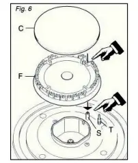 When fitting the wok burner together, it is very important to check that the burner flame distributor (F) and the cap (C) are correctly positioned (fig. 6). Failure to do so can cause problems with ignition and also the way in which the burner operates.Check that the electrode (S) is always clean to ensure trouble-free sparking.Check that the probe (T) is always clean to ensure correct operation of the safety valves (for models with safety device).
 The Wok burner must be correctly positioned (see fig.7). The burner rib must lock into position on the assembly below. If positioned correctly, the burner will not rotate (fig.8).Then position the enamel cap A and the enamel ring B (fig.8).The four holes around the outside of the crown must always be kept clean.
When cleaning, remove the flame divider (fig.9) and use a cotton bud, toothbrush, or a stiff wire brush to clean out any incrustations or dirt from the four holes marked “H” (fig.10).
This procedure is necessary to ensure the burner functions correctly.
Maintenance
Clean burner tops and trivets at least once a week, or after any spillage. Check injectors are not blocked and the electrode and probe are clean.Gas inlet pipes should be checked periodically for leakages (see section on leak testing) a minimum of every 12 months.Lubrication of gas valves – This can only be performed by an authorised person. It may be required if the gas tap become stiff and difficult to turn.
report this ad
References
[xyz-ips snippet=”download-snippet”]