1247 – EN – Omegon Push + Mini-Montierung
![]()
Instruction Manual
Omegon® Push+ Mini mountArt. Nr. – 55041
Instruction Manual
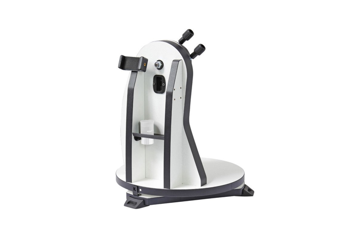
Congratulations on the purchase of the new Omegon® Push+ Mini mount. This mount with a dual encoder-system is compatible with most telescopes equipped with a Vixen-Style dovetail. The Dobson-style telescope mount reads the absolute encoders positions and transmits this information via Bluetooth® to a smartphone, tablet or computer. A dedicated software or app is required to interpret the encoder information and display it on screen allowing the user to calibrate and search for deep-sky objects.
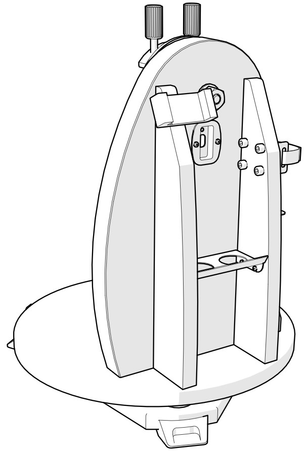
Parts
- Dovetail knob (2 pcs);
- Altitude Axis;
- Smartphone holder;
- Eyepiece-tray;
- Power-bank holder;
- Dovetail holder;
- Main board;
- Cable;

- Side panel;
- Plate-Right;
- Plate-Left.
- Rubber foot;
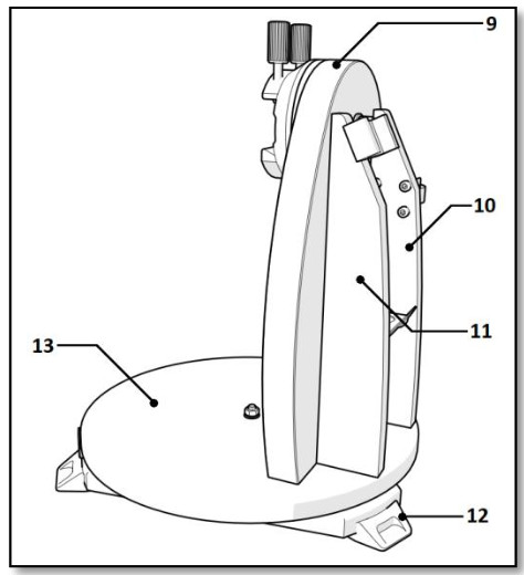
Disc base;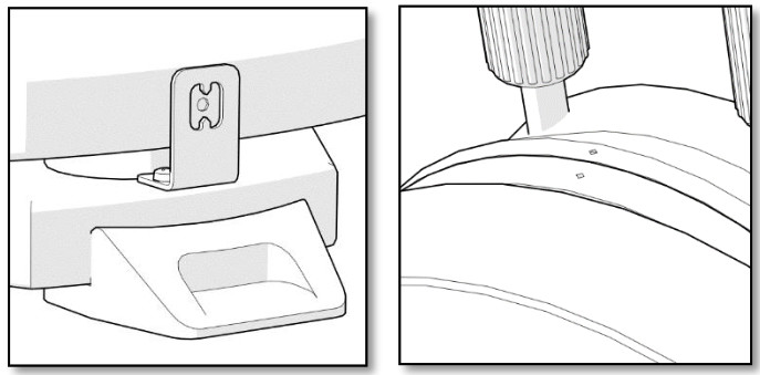 Azimuth axisplace the white dot aligned with vertical spikes.Altitude axisAlign both back and white dots.
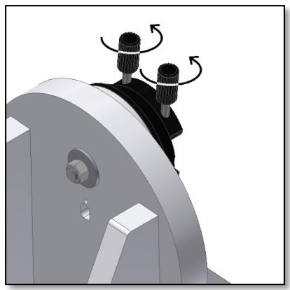 Figure A. Release the two dovetail knobs (part 1)
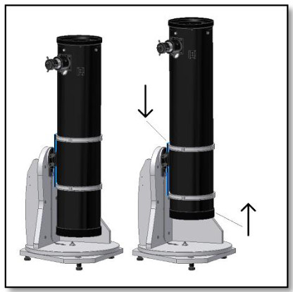 Figure B. Move the dovetail down and the tube up!
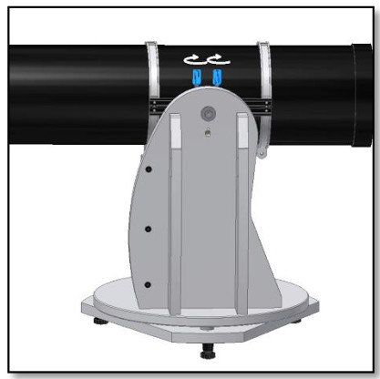 Figure C. Slide the telescope dovetail and tighten firmly the two knobs.
Parts
The Omegon® Push+ Mini Mount is supplied pre-assembled, no additional assembly is necessary. Please take some time to identify the different mount parts in the figures above.
First align indexes, then power!
The Push+ technology relies on absolute encoders. The encoders have been previously calibrated based on a set of Altitude and Azimuth indexes. Please align indexes (as shown on the right) with the mount unpowered. Only after the indexes alignment is made should you power your mount using the supplied cable.
Mounting the telescope tube to the Push+ base.
First thing to do is to rotate the dovetail knobs (part 1) to the upright position and release them so that the dovetail’s slot is unobstructed figure A. Hold the tube and match the telescope dovetail Vixen-style to the dovetail holder (part 6) and tighten the two dovetail knobs (part 1) figure C. It is important that the tube is balanced to the dovetail so that it does not tilt either to the front or the back.
- Balancing the tube. Slide the tube or the dovetail to the front or the back to achieve perfect balancing.
- Powering Push+ base. In order for the digital encoders and the electronics built around it to work and transmit the axes absolute positions of the telescope, a power supply is required. The Push+ is designed to work with a 12Volt DC power supply. We recommend using a field battery for that purpose. Please pay attention when connecting power to the Push+.Exceeding the recommended 12Volt DC power will destroy the electronic components!Figure D. Location of the power socket and the red LED.Power FeaturesPower Supply requirements: 12Volt DC Jack 2.1mm with positive in the centre. Power consumption (idle): 100 mA/h Power consumption (average): 150mA/h Connection socket type: Jack 2.1mmWhen the Push+ is powered, the red LED (part 5) on the side panel will light up and blink. This means the Push+ is connected to power and ready to pair with a Bluetooth® compatible device.1. Powering Push+ with Car cigarette socket cable.The supplied Car cigarette socket cable (figure 1) allows to connect the Push+ to a field battery. Positive pole is in the inside. Please make sure the field battery matches this specification – it has the symbol on the right.2. Powering Push+ with USB Powerbanks.There are many USB powerbanks available that are used commonly to charge smartphones, tablets and other 5Volt devices through a USB port. These batteries vary in terms of capacity and features. The smallest ones have a capacity of about 1500 mA/h and only a USB Out port. They are quite small and can be easily transported to the field as they are pocket size batteries. Most of them don’t supply enough voltage to power the Push+. Some of them have 9Volt or 12Volt outputs. These are great as they can be connected directly to the Push+.Figure 1. The car cigarette socket plug (supplied).Figure 2. USB powerbank/battery (not supplied)Figure 3. Converter cable (not supplied).3. Power booster cables.Some small USB (5Volt) Batteries can also be used to power the Push+. Although the Push+ base is rated to 12V, with a power jump cable, the 5Volt can be increased to the required 12Volt. These cables are available from different suppliers. These small USB batteries with a converter cable have capacity to run the Push+ for more than 8 hours.
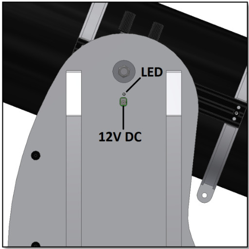 Figure D. Location of the power socket and the red LED.Power FeaturesPower Supply requirements: 12Volt DC Jack 2.1mm with positive in the centre. Power consumption (idle): 100 mA/h Power consumption (average): 150mA/h Connection socket type: Jack 2.1mmWhen the Push+ is powered, the red LED (part 5) on the side panel will light up and blink. This means the Push+ is connected to power and ready to pair with a Bluetooth® compatible device.1. Powering Push+ with Car cigarette socket cable.The supplied Car cigarette socket cable (figure 1) allows to connect the Push+ to a field battery. Positive pole is in the inside. Please make sure the field battery matches this specification – it has the symbol on the right.
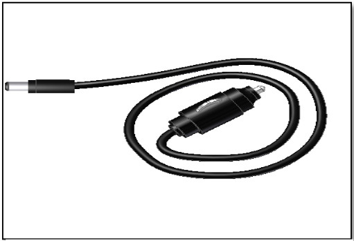 Figure 1. The car cigarette socket plug (supplied).
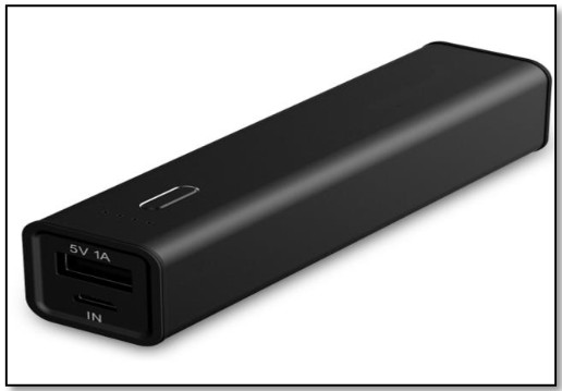 Figure 2. USB powerbank/battery (not supplied)
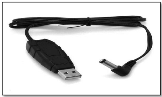 Figure 3. Converter cable (not supplied).3. Power booster cables.Some small USB (5Volt) Batteries can also be used to power the Push+. Although the Push+ base is rated to 12V, with a power jump cable, the 5Volt can be increased to the required 12Volt. These cables are available from different suppliers. These small USB batteries with a converter cable have capacity to run the Push+ for more than 8 hours.
Coordinate System
The Push+ uses two encoders, one on each axis. They measure angular changes to the telescope’s position and “pass” this information to the electronics. These are relative changes, meaning that the Push+ must be calibrated for every observing session – during the session as well to a known set of objects to “know” where it is pointing to. The two altitude and azimuth relative axial positions are transformed into signals that can be interpreted by a dedicated planetarium App. The App will then, based on the current time and location, transform these coordinates into night-sky coordinates. To get the best performance, these two altitude and azimuth coordinates need to be orthogonal to the ground where the Push+ sits. So making the mount horizontal is very important to achieve good results.Important: The mount should be horizontal so that the encoder system is orthogonal to the ground!
- Making the mount horizontal to the ground. To obtain the best pointing precision, we recommend making the mount horizontal. Place the Push+ on a good-levelled ground. An inclined driveway should be avoided! Place a bubble level (builders bubble level not supplied) on the Push+ disc. The level should point to the centre (az-axis) and to one of the plastic foot-set. Rotate the foot-base if necessary so that the bubble shows horizontal levelling. Now, without touching the level, rotate the Push+ so that the level is aligned with the next foot-set. Adjust the foot-base if necessary. Proceed likewise to the last of the foot-set, this one should confirm that the base is levelled. Repeat if necessary until a good horizontal base is reached. Make sure at this point:1. Mount is levelled;2. Optical tube fixed to the Push+;3. Push+ is powered (red LED blinking).You are now ready to go to the next step.
Preparing the Push+ to be used with a device and dedicated App.
The Push+ alone cannot point to a sky object. The Push+ is only the encoder and the integrated Bluetooth® transmission system. One still needs a device smartphone, tablet or computer, and an app. The smartphone or the computer is used to work as a display for the software that will use the relative encoder’s positions to point the telescope to a target. One of the most popular software for telescope control is SkySafari. This is a planetarium app that works virtually with every telescope system. Push+ is also compatible with many other software or apps. We will continuously update software compatibility. Please check our website for software updates and firmware updates.
Push+ compatibility
Push+ is compatible with devices that use Android® or with computers that use Windows® operating system. The devices must also be Bluetooth® 2.0 (or higher) compatible. The following logos apply. Android® logos and symbols are trademarks of Google Inc. Microsoft ® and Windows ® are registered trademarks of Microsoft Corporation. Bluetooth ® is a trademark of Bluetooth SIG Inc.
How to pair Push+ to a device or computer?
Pairing is done as you would do with a cell phone or other device. First power the Push+ by using the supplied power cable or by using a power supply. As soon as Push+ is powered the red LED will start to blink. Now you have two options, you can pair Push+ to an Android® device (phone or tablet) or to a WindowTM based Computer.![]()
- Pairing Push+ to a device like an Android® phone. Make sure you phone is compatible with Bluetooth 2.0 (or higher).Figure 6. Enable the Bluetooth® function.Step 1Enable the Bluetooth® option in your device. Do this by going to the Settings Tab or directly by pressing the Bluetooth® symbol as shown in figure 6.Step 2A window with a list of the available devices will be visible. If you had a previously paired device, it will show up on the list. If Push+ is powered it will also show either as Unknown Device or as Push+.Step 3Select Push+ from the list and pair it by inserting the 4-digit pairing code. Push+ pairing code is “1234” Each Push+ has its own signature and when pairing it will “remember” to which device it is paired. This avoids problems when several Push+ are working close to one another. Remember the maximum recommended Bluetooth® pairing distance is 10m. Make sure you are within this distance. Your Push+ is now paired to your Android® device.
- Pairing Push+ to a laptop or computer. Make sure your computer or laptop is compatible with Bluetooth® 2.0 (or higher). There are several ways to pair your Push+ to a computer. We will describe in the following steps a simple and effective way to do it.Figure 7. Click to show hidden icons.Step 1Select from WindowsTM initial menu the arrow pointing up (show hidden icons) – red circle (right bottom corner on the screen) figure 7.Step 2Click on the Bluetooth® icon. Select “Add Bluetooth device” figure 8Step 3Look for Push+, sometimes it may show up as “unknown device” Click pairStep 4Insert pairing code “1234” Your Push+ is now paired with your computer.Figure 8. Add Bluetooth® device.
- Selecting COM port for apps such as SkyCharts (Cartes du ciel)When pairing a device to a computer via Bluetooth® a COM port is automatically assigned to the device so that it “talks” to the computer and vice-versa. To determine which port corresponds to the Push+ please follow these steps.Figure 9. Right-click “Open settings” on the Bluetooth® symbol.Step 1Select from the WindowsTM initial menu the arrow pointing up (show hidden icons) as shown in 7.2.Step 2Right-click on the Bluetooth® icon. Select “Open Settings”.Step 3Make sure the Discovery check box is checked as show in figure 9. Click “OK”.Step 4Select “COM Ports” figure 10.Figure 10. Click “COM” tab.Step 5An incoming COM port was already assigned to Push+. Select “Push+ Dev B”. Click “Add” button figure 11.Figure 11. Click “Add”.Step 6We now need to select the Outgoing port. Select “Outgoing” if not already selected.Step 7Click on the drop-down menu and select “Push+”.Figure 12. Select “Outgoing” and “Push+”Step 8From the Service area select “Dev B”.Step 9Click “OK”.Figure 13. Select “Dev B”, click “OK”.Step 10The two assigned COM ports will show up. The “Push+ Dev B” COM port number should be used with softwares that require this setting information such as “Cartes du Ciel”.Figure 14. The assigned COM ports will show up. Use this information for the settings of “Cartes du Ciel” or other computer softwares that required this setup information.
- “Cartes du Ciel”. Settings for this planetarium software.Step 1To configure “Cartes du Ciel” select “Telescope” and click “Telescope settings”Figure 15. Telescope settings.Step 2Select “Encoders” if not yet selected.Step 3Click “OK”Figure 16. Select “Encoders”.Step 4Click on “Control panel” to configure the encoder pulses.Figure 17. Select “Control panel”Step 5Select the “Encoder Configuration” tab and change so that it reads as shown: Type: “Intelliscope” Steps (Alpha): “36000” Steps (Delta): “36000” Read Interval (ms): “100” Mount type: “Alt-Az” Encoder initialization angle: “90” Latitude: “insert your latitude here” Longitude: “insert your longitude here” Form always visible: check this boxStep 6Click “Save Setting”Figure 18. Select “Control panel”Step 7Select “Port Configuration” tab and change so that it reads as shown: Serial Port: use the data from 7.3 Step 10 Speed: “115200” Data bits: “8” Parity: “N” Stop bits: “1” Timeout (ms): “1000” Interval Timeout: “400”Step 8Click on “Save Settings” when finished.Figure 19. Port configuration.Figure 20. Click “Connect”.Step 9Select the “Coordinates” tab and click “Connect”. The red square will turn green and some numbers will show up in the upper blank spaces.You are now ready to start using “Cartes du Ciel”!
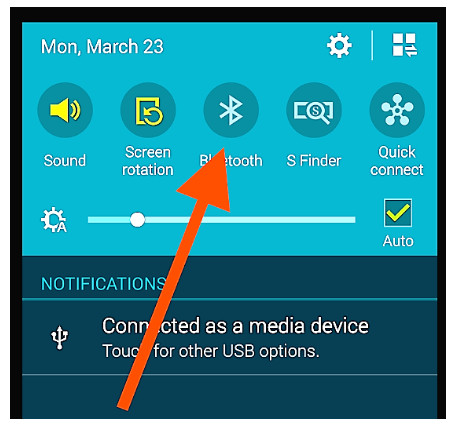 Figure 6. Enable the Bluetooth® function.Step 1Enable the Bluetooth® option in your device. Do this by going to the Settings Tab or directly by pressing the Bluetooth® symbol as shown in figure 6.Step 2A window with a list of the available devices will be visible. If you had a previously paired device, it will show up on the list. If Push+ is powered it will also show either as Unknown Device or as Push+.Step 3Select Push+ from the list and pair it by inserting the 4-digit pairing code. Push+ pairing code is “1234” Each Push+ has its own signature and when pairing it will “remember” to which device it is paired. This avoids problems when several Push+ are working close to one another. Remember the maximum recommended Bluetooth® pairing distance is 10m. Make sure you are within this distance. Your Push+ is now paired to your Android® device.
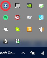 Figure 8. Add Bluetooth® device.
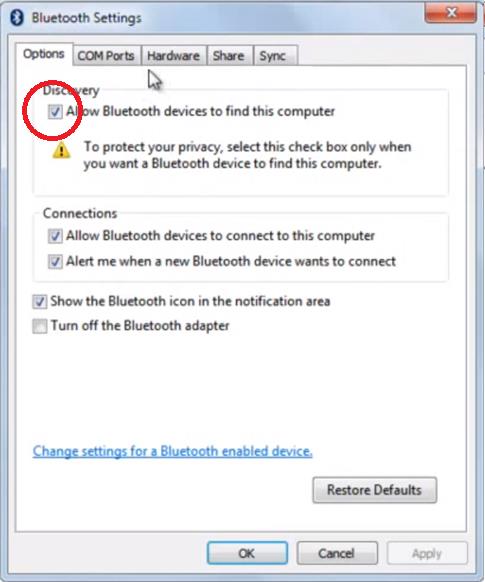 Figure 9. Right-click “Open settings” on the Bluetooth® symbol.Step 1Select from the WindowsTM initial menu the arrow pointing up (show hidden icons) as shown in 7.2.Step 2Right-click on the Bluetooth® icon. Select “Open Settings”.Step 3Make sure the Discovery check box is checked as show in figure 9. Click “OK”.Step 4Select “COM Ports” figure 10.
 Figure 10. Click “COM” tab.Step 5An incoming COM port was already assigned to Push+. Select “Push+ Dev B”. Click “Add” button figure 11.
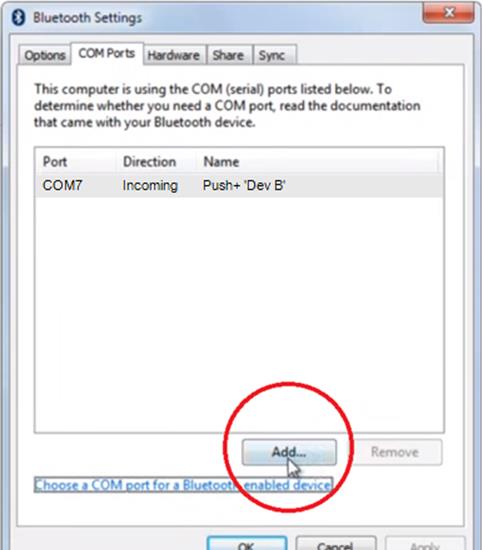 Figure 11. Click “Add”.Step 6We now need to select the Outgoing port. Select “Outgoing” if not already selected.Step 7Click on the drop-down menu and select “Push+”.
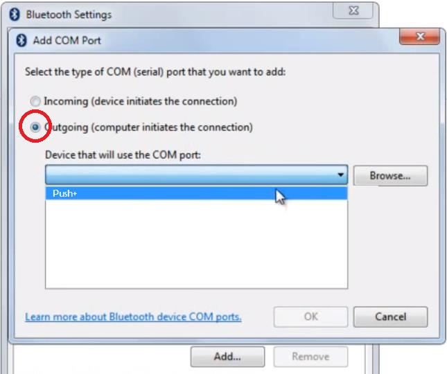 Figure 12. Select “Outgoing” and “Push+”Step 8From the Service area select “Dev B”.Step 9Click “OK”.
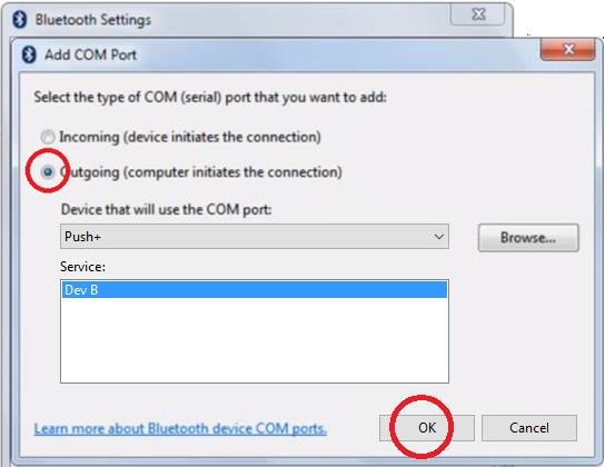 Figure 13. Select “Dev B”, click “OK”.Step 10The two assigned COM ports will show up. The “Push+ Dev B” COM port number should be used with softwares that require this setting information such as “Cartes du Ciel”.
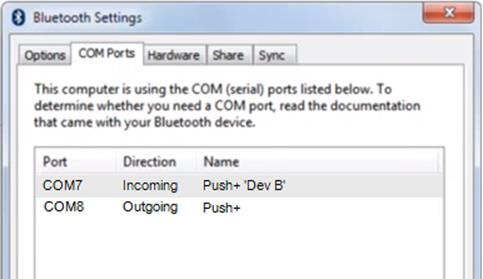 Figure 14. The assigned COM ports will show up. Use this information for the settings of “Cartes du Ciel” or other computer softwares that required this setup information.
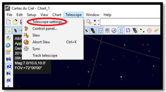 Figure 15. Telescope settings.Step 2Select “Encoders” if not yet selected.Step 3Click “OK”
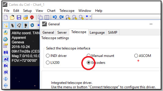 Figure 16. Select “Encoders”.Step 4Click on “Control panel” to configure the encoder pulses.
 Figure 17. Select “Control panel”Step 5Select the “Encoder Configuration” tab and change so that it reads as shown: Type: “Intelliscope” Steps (Alpha): “36000” Steps (Delta): “36000” Read Interval (ms): “100” Mount type: “Alt-Az” Encoder initialization angle: “90” Latitude: “insert your latitude here” Longitude: “insert your longitude here” Form always visible: check this boxStep 6Click “Save Setting”
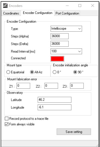 Figure 18. Select “Control panel”Step 7Select “Port Configuration” tab and change so that it reads as shown: Serial Port: use the data from 7.3 Step 10 Speed: “115200” Data bits: “8” Parity: “N” Stop bits: “1” Timeout (ms): “1000” Interval Timeout: “400”Step 8Click on “Save Settings” when finished.
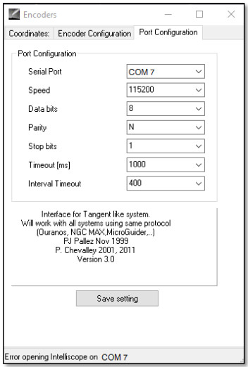 Figure 19. Port configuration.
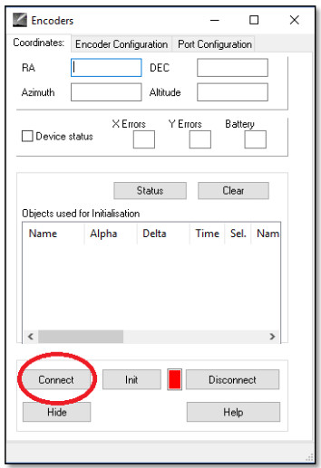 Figure 20. Click “Connect”.Step 9Select the “Coordinates” tab and click “Connect”. The red square will turn green and some numbers will show up in the upper blank spaces.
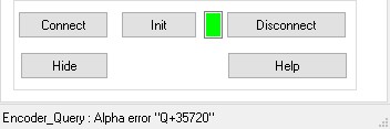 You are now ready to start using “Cartes du Ciel”!
Which software and apps to use?
- SkySafari® from Simulation Curriculum One of the most popular existing planetarium apps is SkySafari® from Simulation Curriculum®. This planetarium app shows the sky on a device screen (they have both Android® and iOS versions) and allows telescope control. It has a huge database with its constellations, deep-sky objects, stars, asterisms and many other objects. To know more visit www.simulationcurriculum.com. SkySafari® is available in several versions from entry level to the most advanced ones. We recommend using the SkySafari® Plus 4 for Android®. It can be downloaded from the Google Play® app centre. Please notice, this is not a free app. The free version does not allow controlling telescopes or Push+. SkySafari® has a quite intuitive interface and is easy to use.
- Cartes du Ciel. This is a very advanced software, which enables precision location of deep-sky objects. While SkySafari® only uses two stars for calibration, “Cartes du Ciel” can use every start or deep-sky object as a calibration object. This is great because for each part of the sky it will use the nearest object as a calibration object increasing dramatically the pointing accuracy. It creates a calibration map for each object calibrated to the system. Any encoder reading error is evenly distributed through the night sky and the software “remembers” the error behaviour making the required compensations. We strongly recommend this software as it is free and very advanced.
Important Push+ Features.
ElectronicsEncoder resolution: 36000 ticks/pulses per axisProtocol: IntelliscopeBluetooth®: 2.0Pairing range: 10m (although when unobstructed can reach up to 30m)
Power CharacteristicsPower: 12Volt DCPower consumption: 150mA/hPower consumption (idle): 100mA/hConnection type: Jack 2.1mm with positive centreMaximum carrying weight: 14kg
Accessories: Smartphone adapter
ShippingShipping box dimensions: 780x760x160mmShipping weight: 20kgNet-Weight: 15kg
Pointing AccuracyUsually between 0.5deg and 0.7deg, should be in the FOV for a 25mm eyepiece with a 8″ Newton OTA.
How to configure the settings to SkySafari®.
SkySafari® has many features that are not covered by the existing instruction manual. To configure SkySafari® to be used with Push+ please follow these steps.– Tap on the SkySafari® icon on your device to start the app.– Now from the menu below tap “Settings” ![]() . This will open the settings menu.
. This will open the settings menu.
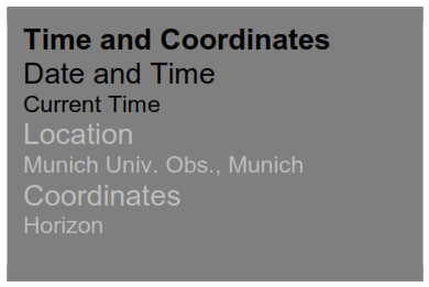 Tap Date and Time, insert current date and time. It is important to get this data the most accurate possible as the pointing accuracy will rely on this given data.
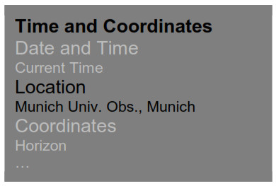 Tap Location, insert your location, please do not forget to choose your hemisphere N/S and meridian position W/E. Most WestEuropean countries are GMT +1 exceptions are UK, IRL and PT, which are GMT.
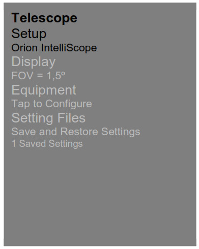 Tap Setup, a scope setup settings tab will showEquipment SelectionScope Type — Orion IntelliScope Mount Type — Alt-Az. Push-To
Communication Settings![]() Connect via Bluetooth
Connect via Bluetooth![]() Connect via WIFICommon Settings
Connect via WIFICommon Settings![]() Set Time & Location
Set Time & Location![]() Save Log File
Save Log File
Readout Rate 10 per secondPlease make sure that when inserting the Mount Type — Alt-Az. Push-To you select and insert the following parameters
Mount Type![]() Equatorial Push-To
Equatorial Push-To![]() Equatorial GoTo (Fork)
Equatorial GoTo (Fork)![]() Equatorial GoTo (German)
Equatorial GoTo (German)![]() Alt-Az. Push-To on Equ. Platform
Alt-Az. Push-To on Equ. Platform![]() Alt-Az. Push-To
Alt-Az. Push-To![]() Alt-Az. GoTo____________________________________________Encoder Steps Per Revolution(Plus = cloclwise; Minus = counterclockwise)RA/Azm: +36000RA/Azm: +36000
Alt-Az. GoTo____________________________________________Encoder Steps Per Revolution(Plus = cloclwise; Minus = counterclockwise)RA/Azm: +36000RA/Azm: +36000![]() Get Automatically
Get Automatically
- Connecting SkySafari® App to Push+. Make sure you followed all the steps. This is really important as without this information SkySafari® will not be able to work with Push+. It is very important at this point to exit the app and re-start it.
Important!
After the settings are done, please exit the App and re-start it so that SkySafari® assumes the recent changes to the settings!
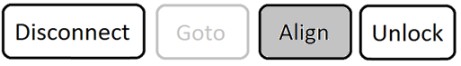
- Connect. Tap “Connect” to connect the telescope to Push+. Connection may take a few seconds. When connection is established, the red LED stops blinking and remains powered ON.
- Cross hair. As soon as connection is established, a crosshair will randomly appear on the screen. If you move the telescope on both axes, you will see this crosshair moving accordingly. This is a good sign; it means both encoders are working. When calibrated, the crosshair will point to a certain region in the sky. This region will match the field of view as seen through the telescope eyepiece.
- Choosing calibration stars. Alignment is done with one-star or two-stars. We recommend the two-star alignment as it provides a much better pointing accuracy. The two-star separation should be no more than 30 degrees but no less than 10 degrees – both in Altitude (Alt) and Azimuth (Az). Avoid using alignment stars closeRule. Always Up and Left – for consistent results we recommend that the final fine adjustments to the object centring in the telescope’s eyepiece to be made Up in Alt and Left in Az.to the horizon and zenith.Step 1Centre a bright star – a star that you know or recognize from a constellation – in the centre of eyepiece field of view. Follow the rule mentioned above final movements always Up and Left. It is important to centre the star in the eyepiece field of view with some accuracy, we recommend using a crosshair eyepiece for this procedure.Step 2Match the star to the one shown on the device’s screen. Just swipe the screen so that the sky rotates and zoom in our out to look for that particular object. Make sure you know the object matches the one observed through the eyepiece a common mistake is aligning the wrong object. Tap on the star. A small cross will show on top of the star.Step 3Tap “Align” to use that star.“Align Telescope?”For a one-star alignment, this is enough. Tap “Align”. The selected star also named “First Target” or “First Alignment Star” was used for calibration. You will now see the crosshair moving across the screen pointing approximately to the same direction as the telescope. For additional pointing accuracy, we recommend using a second alignment star.Select a second star and align, make sure it is not more than 30 degrees apart from the “First Target”. Alignment should be successful. You are now ready to point to objects using your Push+.
 “Align Telescope?”For a one-star alignment, this is enough. Tap “Align”. The selected star also named “First Target” or “First Alignment Star” was used for calibration. You will now see the crosshair moving across the screen pointing approximately to the same direction as the telescope. For additional pointing accuracy, we recommend using a second alignment star.
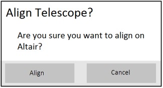 Select a second star and align, make sure it is not more than 30 degrees apart from the “First Target”. Alignment should be successful. You are now ready to point to objects using your Push+.
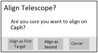
Troubleshooting with SkySafari®
The most common problems as described below.
| Solution | Solution |
| Crosshair does not move | If the connection cable is not properly installed, the encoder position is not read. Please check cable connection. |
| SkySafari® gives an error message when aligning the second target | There is a big difference between the position read by the encoders and the object’s database coordinates. Please make sure you use the right-hand rule (up-left). If the problem persists, make sure you are not using a star too close to the first one. |
| I get pointing errors higher than 0.7 degrees | Make sure the two alignment-stars are not separated more than 30 degrees. |
| Objects are completely off the FOV. | Wrong star used for alignment. |
Step by step use procedure
To use Push+ please make sure you always follow this procedure completing each step before moving to the next one.
Position the mount horizontal to the groundFollow the instructions mentioned in 4.1.
Align indexesMake sure to align the indexes before powering the mount.
Power Push+Follow the instructions
Pair Push+ via Bluetooth (this only needs to be done once)Follow the instructions mentioned in 7.1. or 7.2.
Adjust app settings (SkySafari® or other app)Follow the instructions mentioned in 10.
Connect device to AppFollow the instructions mentioned in 11.
Align/CalibrateFollow the instructions mentioned in 11.
Locate objects and observeFollow the instruction mentioned in 11.
The complete or partial reproduction of the contents of this document outside of private use is expressly prohibited in every way. Errors and omissions excepted.All texts, photos and drawings are the property of nimax GmbH.
References
[xyz-ips snippet=”download-snippet”]