ONKYO A-9050/ A-9030 Integrated Amplifier
Instruction Manual

Thank you for purchasing an Onkyo Integrated Amplifier. Please read this manual thoroughly before making connections and plugging in the unit. Following the instructions in this manual will enable you to obtain optimum performance and listening enjoyment from your new Integrated Amplifier. Please retain this manual for future reference.
WARNING:TO REDUCE THE RISK OF FIRE OR ELECTRIC SHOCK, DO NOT EXPOSE THIS APPARATUS TO RAIN OR MOISTURE.
CAUTION:TO REDUCE THE RISK OF ELECTRIC SHOCK, DO NOT REMOVE COVER (OR BACK). NO USER-SERVICEABLE PARTS INSIDE. REFER SERVICING TO QUALIFIED SERVICE PERSONNEL.
![]()

![]()
![]()
The lightning flash with arrowhead symbol, within an equilateral triangle, is intended to alert the user to thepresence of uninsulated “dangerous voltage” within the product’s enclosure that may be of sufficient magnitude to constitute a risk of electric shock to persons.
![]()
The exclamation point within an equilateral triangle is intended to alert the user to the presence of important operating and maintenance (servicing) instructions in the literature accompanying the appliance.
Important Safety Instructions
- Read these instructions.
- Keep these instructions.
- Heed all warnings.
- Follow all instructions.
- Do not use this apparatus near water.
- Clean only with dry cloth.
- Do not block any ventilation openings. Install in accordance with the manufacturer’s instructions.
- Do not install near any heat sources such as radiators, heat registers, stoves, or other apparatus (including amplifiers) that produce heat.
- Do not defeat the safety purpose of the polarized or grounding-type plug. A polarized plug has two blades with one wider than the other. A grounding type plug has two blades and a third grounding prong. The wide blade or the third prong are provided for your safety. If the provided plug does not fit into your outlet, consult an electrician for replacement of the obsolete outlet.
- Protect the power cord from being walked on or pinched particularly at plugs, convenience receptacles, and the point where they exit from the apparatus.
- Only use attachments/accessories specified by the manufacturer.
- Use only with the cart, stand, tripod, bracket, or table specified by the manufacturer, or sold with the apparatus. When a cart is used, use caution when moving the cart/apparatus combination to avoid injury from tip-over.

- Unplug this apparatus during lightning storms or when unused for long periods of time.
- Refer all servicing to qualified service personnel. Servicing is required when the apparatus has been damaged in any way, such as power-supply cord or plug is damaged, liquid has been spilled or objects have fallen into the apparatus, the apparatus has been exposed to rain or moisture, does not operate normally, or has been dropped.
- Damage Requiring ServiceUnplug the apparatus from the wall outlet and refer servicing to qualified service personnel under the following conditions:
- A. When the power-supply cord or plug is damaged,
- B. If liquid has been spilled, or objects have fallen into the apparatus,
- C. If the apparatus has been exposed to rain or water,
- D. If the apparatus does not operate normally by following the operating instructions. Adjust only those controls that are covered by the operating instructions as an improper adjustment of other controls may result in damage and will often require extensive work by a qualified technician to restore the apparatus to its normal operation,
- E. If the apparatus has been dropped or damaged in any way, and
- F. When the apparatus exhibits a distinct change in performance this indicates a need for service.
- Object and Liquid EntryNever push objects of any kind into the apparatus through openings as they may touch dangerous voltage points or short-out parts that could result in a fire or electric shock.The apparatus shall not be exposed to dripping or splashing and no objects filled with liquids, such as vases shall be placed on the apparatus. Don’t put candles or other burning objects on top of this unit.
- BatteriesAlways consider the environmental issues and follow local regulations when disposing of batteries.
- If you install the apparatus in a built-in installation, such as a bookcase or rack, ensure that there is adequate ventilation.(Leave 20 cm (8″) of free space at the top and sides and 10 cm (4″) at the rear. When a shelf is located above the unit, the rear edge of the shelf shall be set 10 cm (4″) away from the backboard to improve ventilation.)

Precautions
- Recording Copyright—Unless it’s for personal use only, recording copyrighted material is illegal without the permission of the copyright holder.
- AC Fuse—The AC fuse inside the unit is not user-serviceable. If you cannot turn on the unit, contact your Onkyo dealer.
- Care—Occasionally you should dust the unit all over with a soft cloth. For stubborn stains, use a soft cloth dampened with a weak solution of mild detergent and water. Dry the unit immediately afterwards with a clean cloth. Don’t use abrasive cloths, thinners, alcohol, or other chemical solvents, because they may damage the finish or remove the panel lettering.
- PowerWARNINGBEFORE PLUGGING IN THE UNIT FOR THE FIRST TIME, READ THE FOLLOWING SECTIONCAREFULLY.AC outlet voltages vary from country to country. Make sure that the voltage in your area meets the voltage requirements printed on the unit’s rear panel (e.g., AC 230 V, 50 Hz or AC 120 V, 60 Hz). The power cord plug is used to disconnect this unit from the AC power source. Make sure that the plug is readily operable (easily accessible) at all times.For models with [POWER] button, or with both [POWER] and [ON/STANDBY] buttons: Pressing the [POWER] button to select OFF mode does not fully disconnect from the mains. If you do not intend to use the unit for an extended period, remove the power cord from the AC outlet.For models with [ON/STANDBY] button only: Pressing the [ON/STANDBY] button to select Standby mode does not fully disconnect from the mains. If you do not intend to use the unit for an extended period, remove the power cord from the AC outlet.
- Preventing Hearing LossCautionExcessive sound pressure from earphones and headphones can cause hearing loss.
- Batteries and Heat ExposureWarningBatteries (battery pack or batteries installed) shall not be exposed to excessive heat as sunshine, fire or the like.
- Never Touch this Unit with Wet Hands—Never handle this unit or its power cord while your hands are wet or damp. If water or any other liquid gets inside this unit, have it checked by your Onkyo dealer.
- Handling Notes
- If you need to transport this unit, use the original packaging to pack it how it was when you originally bought it.
- Do not leave rubber or plastic items on this unit for a long time, because they may leave marks on the case.
- This unit’s top and rear panels may get warm after prolonged use. This is normal.
- If you do not use this unit for a long time, it may not work properly the next time you turn it on, so be sure to use it occasionally.
For U.S. modelsFCC Information for User
CAUTION:The user changes or modifications not expressly approved by the party responsible for compliance could void the user’s authority to operate the equipment.
NOTE:This equipment has been tested and found to comply with the limits for a Class B digital device, pursuant to Part 15of the FCC Rules. These limits are designed to provide reasonable protection against harmful interference in aresidential installation. This equipment generates, uses and can radiate radio frequency energy and, if not installed and used in accordance with the instructions, may cause harmful interference to radio communications. However, there is no guarantee that interference will not occur in a particular installation. If this equipment does cause harmful interference to radio or television reception, which can be determined by turning the equipment off and on, the user is encouraged to try to correct the interference by one or more of the following measures:
- Reorient or relocate the receiving antenna.
- Increase the separation between the equipment and receiver.
- Connect the equipment into an outlet on a circuit different from that to which the receiver is connected.
- Consult the dealer or an experienced radio/TV technician for help.
For Canadian Models
NOTE: THIS CLASS B DIGITAL APPARATUS COMPLIES WITH CANADIAN ICES-003. For models having a power cord with a polarized plug:
CAUTION: TO PREVENT ELECTRIC SHOCK, MATCH WIDE BLADE OF PLUG TO WIDE SLOT, FULLY INSERT.
For British models
Replacement and mounting of an AC plug on the power supply cord of this unit should be performed only by qualified service personnel.
IMPORTANTThe wires in the mains lead are coloured in accordance with the following code:Blue: NeutralBrown: Live
As the colours of the wires in the mains lead of this apparatus may not correspond with the coloured markings identifying the terminals in your plug, proceed as follows: The wire which is coloured blue must be connected to the terminal which is marked with the letter N or coloured black.
The wire which is coloured brown must be connected to the terminal which is marked with the letter L or coloured red.
IMPORTANTThe plug is fitted with an appropriate fuse. If the fuse needs to be replaced, the replacement fuse must approved by ASTA or BSI to BS1362 and have the same ampere rating as that indicated on the plug. Check for the ASTA mark or the BSI mark on the body of the fuse. If the power cord’s plug is not suitable for your socket outlets, cut it off and fit a suitable plug. Fit a suitable fuse in the plug.
For European Models

Supplied Accessories
Make sure you have the following accessories:
Remote controller and two batteries
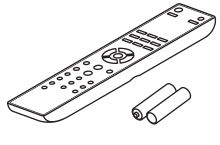
Remote controller (RC-830S) . . . . . . . . . . . . . . . . . . . . (1)Batteries (R03/AAA). . . . . . . . . . . . . . . . . . . . . . . . . . . (2)(Note for China: The battery for the remote controller is not supplied for this unit.)
Power cord (A-9050 only)
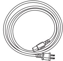
Power cord (5.9 ft/1.8 m). . . . . . . . . . . . . . . . . . . . . . . . (1)(Plug type varies from country to country.)
- In catalogs and on packaging, the letter at the end of the product name indicates the color. Specifications and operations are the same regardless of color.
Features
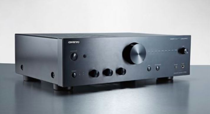
A-9050 Integrated Digital Amplifier
- Three-stage Inverted Darlington Circuitry
- Digital Inputs (Optical/Coaxial)
- Wolfson 192 kHz/24 bit DACs withDIDRC Circuitry Inside (WM8718)
- Phase Matching Bass Technology
- 1.6 mm Full Flat Chassis
- 75 W/ch (1 kHz, 8 ohms, 0.08 % THD, 2ch Driven FTC)
- WRAT (Wide Range Amplifier Technology)
- DIDRC (Dynamic Intermodulation Distortion Reduction Circuiry)
- High Current Low Impedance Drive
- 10,000 µF Capacitor × 2
- Optimum Gain Volume
- Aluminum Front Panels and Volume Knob
- Direct Mode Switch
A-9030 Integrated Digital Amplifier
- Three-stage Inverted Darlington Circuitry
- Phase Matching Bass Technology
- 1.6 mm Full Flat Chassis
- 65 W/ch (1 kHz, 4 ohms, 0.08 % THD, 2ch Driven IEC)
- WRAT (Wide Range Amplifier Technology)
- High Current Low Impedance Drive
- 8,200 µF Capacitor × 2
- Optimum Gain Volume
- Direct Mode Switch
Before Using the Integrated Amplifier
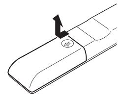
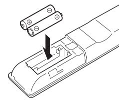
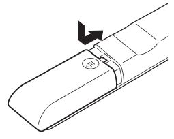
Installing the Batteries
- To open the battery compartment, press the small hollow and slide the cover.
- Insert the two supplied batteries (R03/AAA) in accordance with the polarity diagram inside the battery compartment.
- Replace the cover and slide it shut.
Note
- If the remote controller doesn’t work reliably, try replacing the batteries.
- Don’t mix new and old batteries or different types of batteries.
- If you intend not to use the remote controller for a long time, remove the batteries to prevent damage from leakage or corrosion.
- Remove expired batteries as soon as possible to prevent damage from leakage or corrosion.
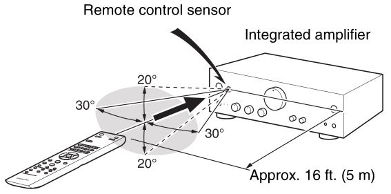
Using the Remote Controller
To use the remote controller, point it at the integrated amplifier’s remote control sensor, as shown below.
Note
- The remote controller may not work reliably if the integrated amplifier is subjected to bright light, such as direct sunlight or inverter-type fluorescent lights. Keep this in mind when installing.
- If another remote controller of the same type is used in the same room, or the integrated amplifier is installed close to equipment that uses infrared rays, the remote controller may not work reliably.
- Don’t put anything, such as a book, on the remote controller, because the buttons may be pressed inadvertently, therebydraining the batteries.
- The remote controller may not work reliably if the integrated amplifier is installed in a rack behind colored glass doors. Keep this in mind when installing.
- The remote controller will not work if there’s an obstacle between it and the integrated amplifier’s remote control sensor.
Installing the Integrated Amplifier
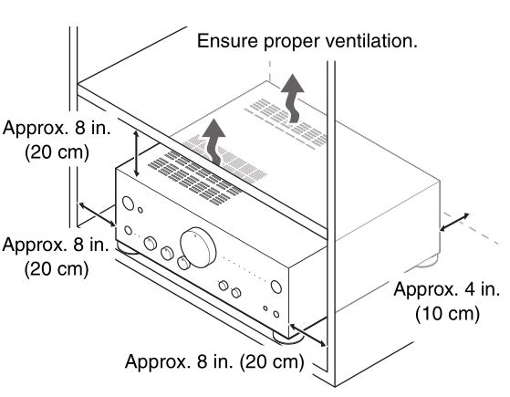
Install the integrated amplifier on a sturdy rack or shelf. Position it so that its weight is evenly dispersed on its four legs. Do not install the integrated amplifier in a place with vibration or an unstable location.
The integrated amplifier is designed to have high conversion efficiency, however, its temperature will become much higher than other audio equipment. Therefore, make sure not to hamper heat dissipation by ensuring proper ventilation.
Getting to Know the Integrated Amplifier
Front Panel
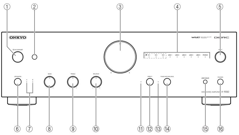
For detailed information, see the pages in parentheses.
- ON/STANDBY button (➔ page 21)Sets the integrated amplifier to On or Standby.
- Remote control sensor (➔ page 7)Receives control signals from the remote controller.
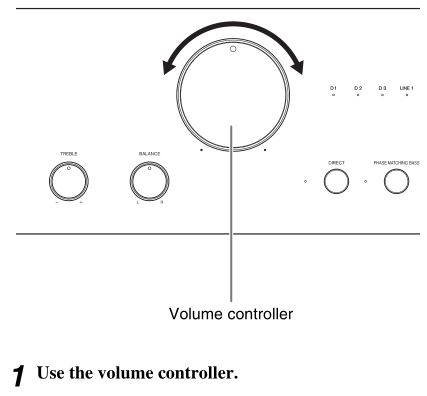
- Volume controller (➔ page 22)Adjusts the volume.
- Input source LEDs (➔ page 23)Lights according to the selected input source. (*A-9050 only)
- INPUT selector (➔ page 23)Selects the input sources in sequence.
- SPEAKERS button (➔ page 22)Selects Speakers A, Speakers B, or both.
- A/B LEDs (➔ page 22)Lights according to the selected speaker output.
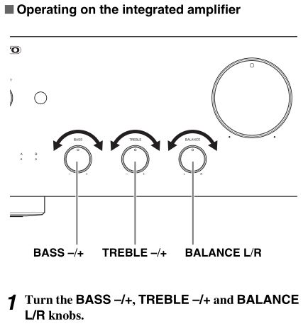
- BASS –/+ controller (➔ page 24)Adjusts the level of bass sounds.
- TREBLE –/+ controller (➔ page 24)Adjusts the level of treble sounds.
- BALANCE L/R controller (➔ page 24)Adjusts the balance of left and right channels.
- DIRECT LED (➔ page 23)Lights when the integrated amplifier is in Direct mode.
- DIRECT button (➔ page 23)Enables or disables the Direct function.
- PHASE MATCHING BASS LED (➔ page 23)Lights when the integrated amplifier is in Phase matching bass mode.
- PHASE MATCHING BASS button (➔ page 23)Enables or disables the Phase matching bass function.
- LINE5 (AUX) jackConnect playback devices with analog audio output.
- PHONES jack (➔ page 24)Connects headphones with a standard plug.
Rear Panel
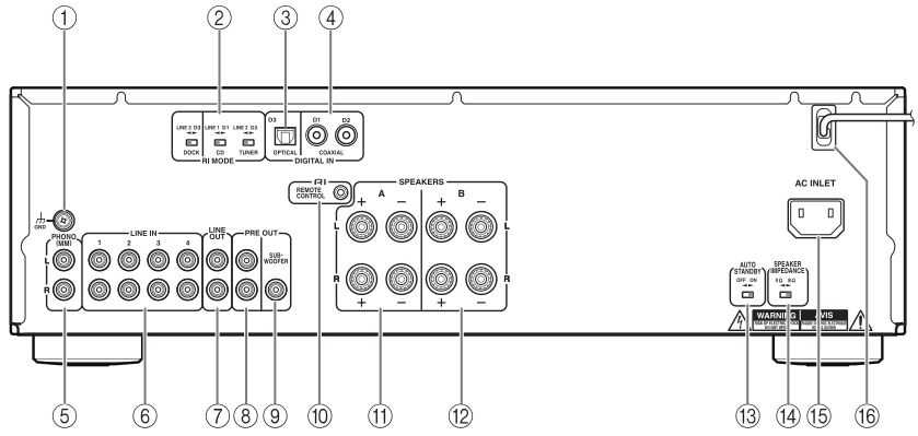
- GND screwConnects the turntable’s ground wire.
- RI MODE selector (A-9050 only)
- DIGITAL IN OPTICAL D3 jack (A-9050 only)Connects components such as CD players with optical digital audio output.
- DIGITAL IN COAXIAL D1/D2 jacks (A-9050 only)Connect components such as CD players with coaxial digital audio output.
- PHONO (MM) L/R jacksConnect a turntable with analog audio output.
- LINE IN 1/2/3/4 L/R jacksConnect playback devices with analog audio output.
- LINE OUT L/R jacksConnect components such as analog line-level sources. The input signals are output with no level adjustment.
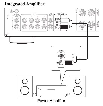
- PRE OUT L/R jacks (A-9050 only)Connect a power amplifier when the integrated amplifier is used as a preamplifier (Pre mode).
- PREOUT SUBWOOFER jack
- RI REMOTE CONTROL jackConnect Onkyo components such as Onkyo Docks, CD Players, or Tuner with u (Remote Interactive) jacks.
- SPEAKERS A terminalsConnect Speakers A.
- SPEAKERS B terminalsConnect Speakers B.
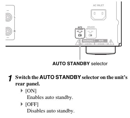
- AUTO STANDBY selectorEnables or disables the Auto standby function.
- SPEAKER IMPEDANCE selector (A-9050 only)Switches the speaker impedance to 4 Ω or 8 Ω.
- AC INLET (A-9050 only)Connects the supplied power cord. The other end of the power cord should be connected to a suitable wall outlet.
- POWER CORD (A-9030 only)
See “Connections” for connection information (➔ page 12).
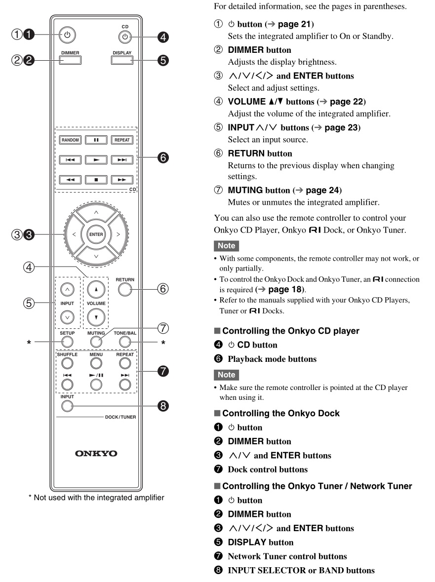
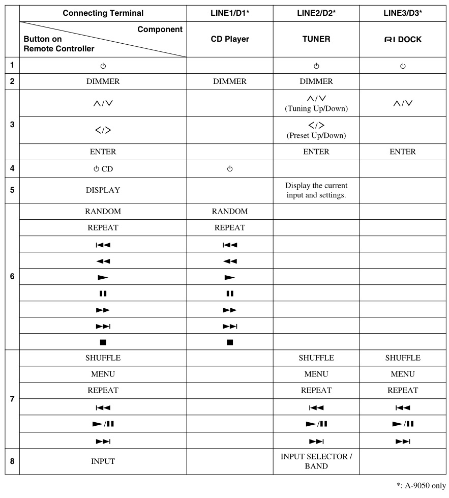
Remote Controller
Connections
Connecting Your Speakers
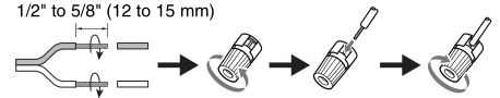
- Screw-type speaker terminalsStrip 1/2″ to 5/8″ (12 to 15 mm) of insulation from the ends of the speaker cables, and twist the bare wires tightly, as shown.
- Banana Plugs (North American models)
- If you are using banana plugs, tighten the speaker terminal before inserting the banana plug.
- Do not insert the speaker code directly into the center hole of the speaker terminal.
Note
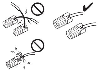
- Make sure that the wires do not touch metal parts on the back panel or elsewhere.
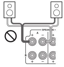
- Y plugs cannot be connected.
- Two sets of speakers (Speakers A and Speakers B) can be connected to the integrated amplifier. You can select which speakers to output audio to when listening to music. You can also output audio from both sets of speakers.
- If you use Speakers A or Speakers B, make sure to use speakers with an impedance of 4 to 16 ohms. If you use Speakers A and Speakers B, make sure to use speakers with an impedance of 8 to 16 ohms. Connecting speakers with an impedance less than 8 ohms may cause the protection circuit to activate.
- When using only one speaker, or when playing back monaural audio, don’t connect a single speaker to both the left and right speaker terminals.
- Pay close attention to speaker wiring polarity. In other words, connect positive (+) terminals only to positive (+) terminals, and negative (–) terminals only to negative (–) terminals. If you get them the wrong way around, the sound will be out of phase and will feel unnatural.
- Be careful not to short the positive and negative wires. Doing so may damage the integrated amplifier.
- Make sure the metal core of the wire does not have contact with the integrated amplifier’s rear panel. Doing so may damage the integrated amplifier.
- Don’t connect more than one speaker wire to a single speaker terminal. Doing so could damage the integrated amplifier or cause it to malfunction.
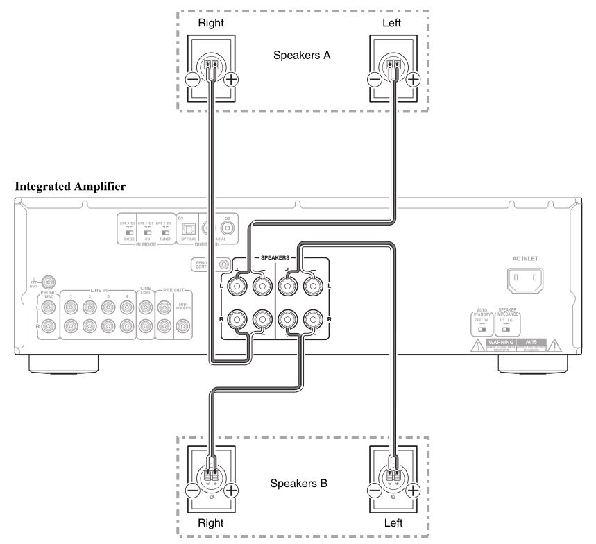
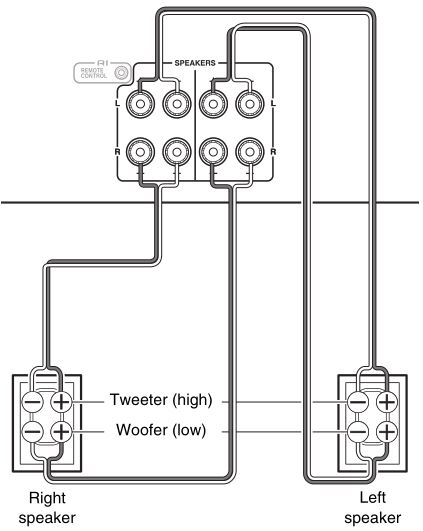
Bi-wiring Connection
Bi-wiring provides improved bass and treble performance. Using terminals of both SPEAKERS A andSPEAKERS B, it separates high frequency from low frequency signals.
Important:
- Bi-wiring can be used only with speakers that support bi-wiring and that have an impedance of 4-16 ohms.
- When making the bi-wiring connections, be sure to remove the jumper bars that link the speakers’ tweeter (high) and woofer (low) terminals.
- When making the bi-wiring connections, set SPEAKERS to A+B (➔ page 22).
Integrated Amplifier
Tip
- As shown on the illustration, the wiring terminals of SPEAKERS A are connected to the tweeter and SPEAKERS B are connected to the woofer. However, wiring them the other way around is also possible.
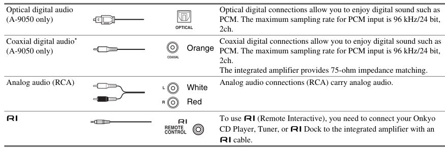
Cable and Jacks
Note
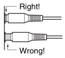
- Push plugs in all the way to make good connections (loose connections can cause noise or malfunctions).
- To prevent interference, keep audio cables away from power cords and speaker cables.
- The integrated amplifier’s optical digital jack have shutter-type covers that open when an optical plug is inserted and close when it’s removed. Push plugs in all the way.
- To prevent shutter damage, hold the optical plug straight when inserting and removing.
- Do not use digital audio signals other than PCM.* An analog audio cable can be used instead of a coaxial cable. However, we recommend that you use a coaxial or a composite video cable.
Connecting the Power Cord
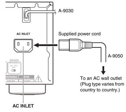
- Connect all of your speakers and components.
- Connect the supplied power cord to the integrated amplifier’s AC INLET. (A-9050 only)
- Plug the power cord into an AC wall outlet.
Tip
- To reduce noise, do not tie signal cables together with the power cable. Wire them so that they are away from each other.
- Depending on the country, the integrated amplifier may be polarity-sensitive. In this case, plug the power cord in a way that provides the best sound quality.
Note
- Never disconnect the power cord from the integrated amplifier while the other end is still plugged into a wall outlet. Doing so may cause an electric shock. Always disconnect the power cord from the wall outlet first, and then the integrated amplifier.
- Turning on the integrated amplifier may cause a momentary power surge that might interfere with other electrical equipment on the same circuit. If this is a problem, plug the integrated amplifier into a different branch circuit.
- Do not use a power cord other than the one supplied with the integrated amplifier. The supplied power cord is designed exclusively for use with the integrated amplifier and should not be used with any other equipment.
Connecting a CD Player
This is an example of connection using the CD Player.
Digital Connection (A-9050 only)
Integrated Amplifier
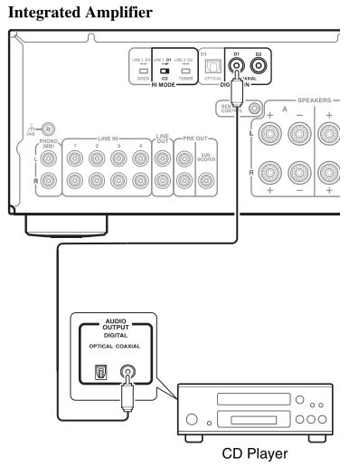
- Connect the coaxial digital cable to the COAXIAL D1 jack.
- Set the RI MODE switch to CD D1.
Tip
- The CD player can be connected to the COAXIAL D1 or D2 jack or the OPTICAL D3 jack. However, when using the RI interlock function, be sure to connect the CD player to the COAXIAL D1 jack.
Analog Connection
Integrated Amplifier
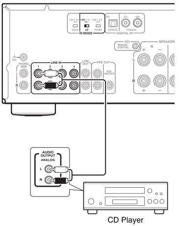
- Connect an audio pin cable to the LINE IN 1 jack.
- Set the RI MODE switch to CD LINE 1. (A-9050 only)
Tip
- The CD player can be connected to the LINE IN 1/2/3/4 jack. However, when using the u interlock function, be sure to connect the CD player to the LINE IN 1 jack.
Connecting a Tuner
This is an example of connection using the Tuner.
Digital Connection (A-9050 only)
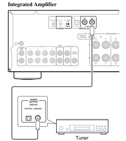
- Connect coaxial digital cable to the COAXIAL D2 jack.
- Set the RI MODE switch to TUNER D2.
Tip
- The Tuner can be connected to the COAXIAL D1 or D2 jack or the OPTICAL D3 jack. However, when using the u interlock function, be sure to connect the Tuner to the COAXIAL D2 jack.
Analog Connection
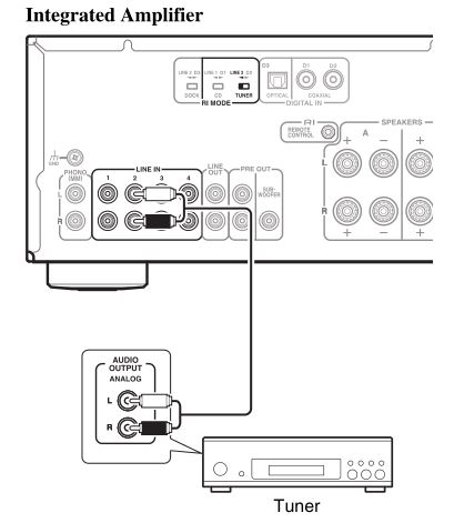
- Connect an audio pin cable to the LINE IN 2 jack.
- Set the RI MODE switch to TUNER LINE 2. (A-9050 only)
Tip
- A Tuner can be connected to the LINE IN 1/2/3/4 jack. However, when using the RI interlock function, be sure to connect the Tuner to the LINE IN 2 jack.
Connecting an Onkyo Dock
This is an example of connection using the Onkyo RI Dock.
Digital Connection (A-9050 only)
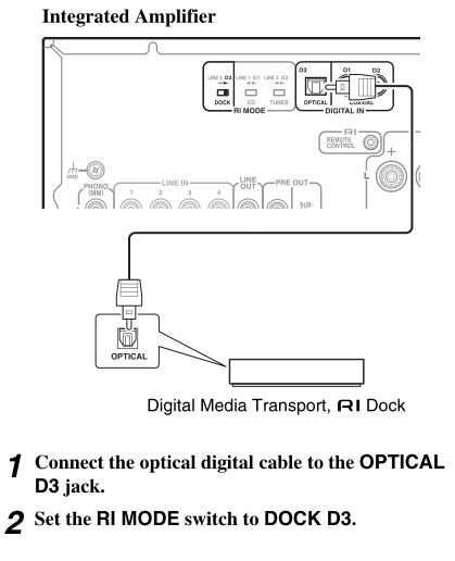
Tip
- An Onkyo Dock can be connected to the LINE IN 1/2/3/4 jack. However, when using the u interlock function, be sure to connect the Onkyo Dock to the LINE IN 3 jack.
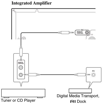
Connecting Onkyo RI Components
- Make sure that each Onkyo CD Player, Tuner or RI Dock is connected and that the RI MODE switch is set correctly (➔ pages 15 to 17).Caution
- Settings will not be enabled even when the selector is changed in the Standby mode.
- To change a setting, be sure to turn on the unit prior to making any changes.
- Make the RI connections (see the illustration). With u (Remote Interactive), you can use the following special functions:
- Auto Power OnWhen you start playback on a component connected via RI while the integrated amplifier is on Standby, the integrated amplifier will automatically turn on and select that component as the input source.
- Direct ChangeWhen playback is started on a component connected via RI, the integrated amplifier automatically selects that component as the input source.
- System OffWhen you turn off the integrated amplifier, the components turn off automatically.
- Remote ControlYou can use the integrated amplifier’s remote controller to control your other u-capable Onkyo Components, pointing the remote controller at the integrated amplifier’s remote control sensor instead of the component.To operate the CD player, point the remote controller at the CD player.
Tip
- For details on operating the connected components, see “Remote Controller” (➔ page 11).
Note
- Use only u cables for u connections. RI cables are supplied with your Onkyo CD Player, Tuner or RI Dock.
- If two RI jacks are present, you can use either one indifferently as they work the same way.
- Connect only an Onkyo CD Player, Tuner or RI Dock to the u jack. Connecting other manufacturer’s components may cause a malfunction.
- Only Onkyo CD Players, Tuners, and RI Docks are supported by the integrated amplifier’s u. With other components such as MD recorders, the u won’t work properly.
- Some components may not support all RI functions. Refer to the manuals supplied with your Onkyo CD Players, Tuner or RI Docks.
- The CD Players only support the Auto Power On and Direct Change functions.
Connecting a Turntable
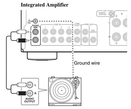
The PHONO input jacks are for use with moving-magnet (MM) type cartridges.Use an analog audio cable to connect the PHONO L/R jacks to the audio output jacks on the turntable, as shown.
Tip
- If the turntable has a ground wire, connect it to GND terminal. With some turntables, connecting the ground wire may cause hum, in which case it should be disconnected.
- If the turntable has a moving-coil (MC) type cartridge, you’ll need a commercially available MC phono preamp. In this case, connect the turntable to the phono preamp’s input, and connect the phono preamp’s output to the PHONO L/R jacks.
Connecting a Cassette Tape Deck
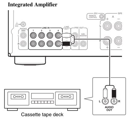
Tip
- Connect your cassette tape deck to either of the following jacks: LINE IN 1/2/3/4.
Connecting a Recording Component
Important:
- Unless you have the full consent of the copyright holder, copyright laws prohibit using your recordings for anything other than personal enjoyment!
- Do not change the integrated amplifier’s input while recording. Doing so will cause the audio from the selected component to be recorded.
Note
- Volume adjustments and use of the muting function are not reflected in the signal output from LINE OUT.
- Manual tone adjustments using the BASS –/+ controller, TREBLE –/+ controller, BALANCE L/R controller, direct function, and phase matching bass function are not reflected in the signal output from LINE OUT.
- See the manual of the recording component for instructions on correct use.

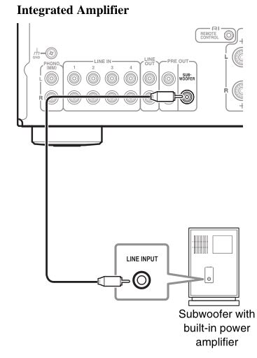
Connecting a Subwoofer With Built-In Power Amplifier
A subwoofer with a built-in power amplifier can be connected to be used.Connect LINE INPUT on the subwoofer with a built-in power amplifier to PRE OUT: SUBWOOFER terminal on the integrated amplifier.If your subwoofer does not have a built-in amplifier, connect the input jack of your amplifier to the pre out jack of the subwoofer.For details, refer to the manual supplied with your subwoofer.
Using the Integrated Amplifier as a Preamplifier
Basic Operations
Turning On/Off the Integrated Amplifier
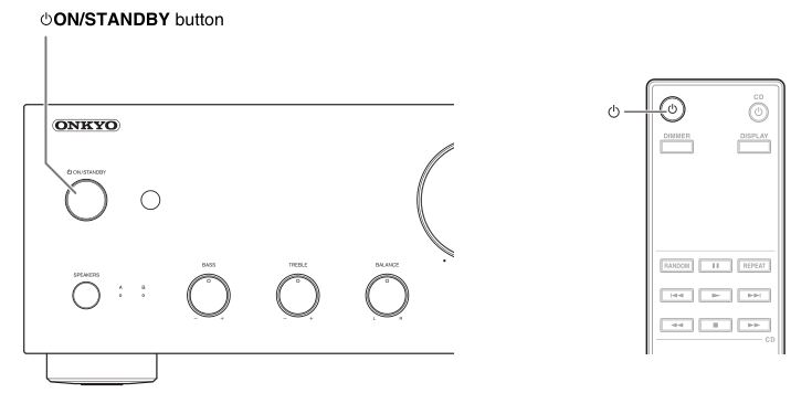
Turning On the Integrated Amplifier
- Operating with the remote controller
- Press Power Button.The SPEAKERS (A/B) and Input source LEDs blink, then light up after a short time.
- Operating on the integrated amplifier
- Press Power ON/STANDBY.The SPEAKERS (A/B) and Input source LEDs blink, then light up after a short time.
Tip
- After a certain time of warming up, the internal temperature of the integrated amplifier stabilizes, and the sound is softened.
- The integrated amplifier remembers the state when power was last turned off, and returns to that state.
Turning Off the Integrated Amplifier
- Operating with the remote controller
- Press Power.The integrated amplifier enters Standby mode and the LED goes off.
- Operating on the integrated amplifier
- Press Power ON/STANDBY.The integrated amplifier enters Standby mode and the LED goes off.
Tip
- For details on power management settings, see “Setting the Auto Standby Function” (➔ page 25).
Selecting Speakers A and Speakers B
You can select to output sound from Speakers A, Speakers B, or both A + B.
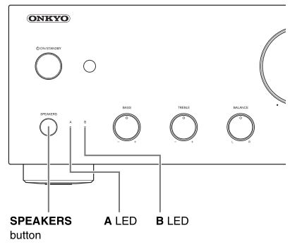
- Press SPEAKERS repeatedly on the integrated amplifier.The LED of the selected speakers lights.
Note
- While headphones are connected, this setting is disabled.
- When this setting is set to A + B, the impedance of speakers is restricted. For further details, see “Connecting Your Speakers” (➔ page 12).
Adjusting the Volume
- Operating with the remote controller
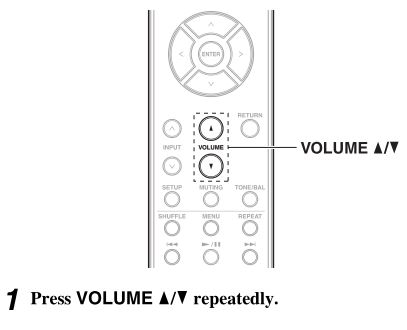
- Press VOLUME ^/v repeatedly.
- Operating on the integrated amplifier
Tip
- The default level is 0.
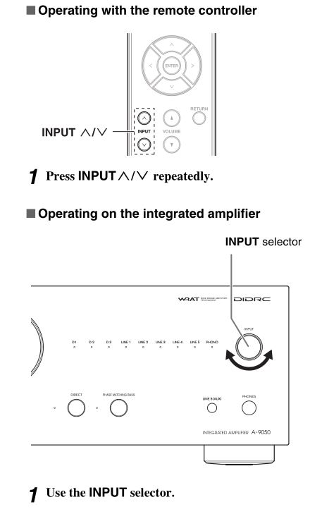
Selecting the Input Source
You can switch inputs to select the desired source component. Choose an input from the following: LINE1, LINE2, LINE3, LINE4, LINE5, PHONO (D1, D2, D3 (A-9050 only))The LED corresponding to the selected input will light up.
Tip
- The LED will blink when D1, D2 or D3 is selected and a signal is not input. (A-9050 only)
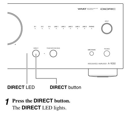
Using the Direct Function
By bypassing the tone control circuit, the Direct function uses the shortest path for enhanced sound quality. Also, since the left/right balance setting uses a system that doesn’t affect the sound quality, the balance can be adjusted even if the Direct function is enabled.
Using the PHASE MATCHING BASS Function
From the warm low notes produced by a cello to the deep frequencies of electronic music, a good compact audio system should be able to deliver plenty of bass resonance. While traditional enhancement systems effectively boost low-frequency sound, they are often prone to the effects of phase shifting, which can overwhelm mid-range frequencies and muddy the sound.Our Phase-Matching Bass Boost technology effectively preserves mid-range clarity-allowing vocals and strings to shine-while maintaining a smooth, powerful bass response at all volume levels.
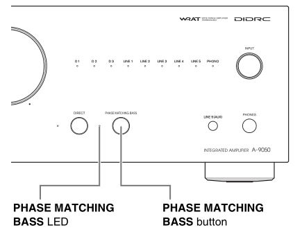
- Press the PHASE MATCHING BASS button. The PHASE MATCHING BASS LED lights up.
- When the DIRECT function is on, turn the function off to use the PHASE MATCHING BASS effect.
Adjusting the Bass, Treble and Balance
You can adjust the bass, treble and left/right output balance respectively.
Tip
- By default, bass, treble and balance is set to the center position.
Note
- While the Direct function is enabled, bass and treble are disabled.
Muting the Sound
You can temporarily mute the output of the integrated amplifier.
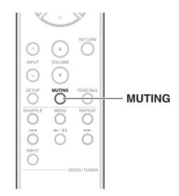
- Press MUTING.The SPEAKERS (A/B) and SELECTOR LEDs blink. To unmute the integrated amplifier, press MUTING again.
Note
- While the integrated amplifier is muted:– Adjusting the volume or setting the integrated amplifier to Standby will unmute the integrated amplifier.
Using Headphones

- Connect a pair of stereo headphones with a standard plug (1/4 inch or 6.3 mm) to the PHONES jack.When connecting the headphones, the SPEAKERS (A/B) LEDs go off.You can adjust the volume and mute the sound, by using VOLUME ^/v.While headphones are connected, no sound is output from the speakers and PRE OUT jacks.
Note
- Always turn down the volume before connecting your headphones.
- When headphones are connected, the SPEAKERS button cannot be used.
Custom Setup
Setting the Auto Standby Function
When the Auto Standby (ASb) function is activated, the integrated amplifier will automatically enter Standby mode if there is no operation for 30 minutes with no audio signal input.
Setting the speaker impedance
You can set the impedance of the speakers that you connect to the unit. (A-9050 only)
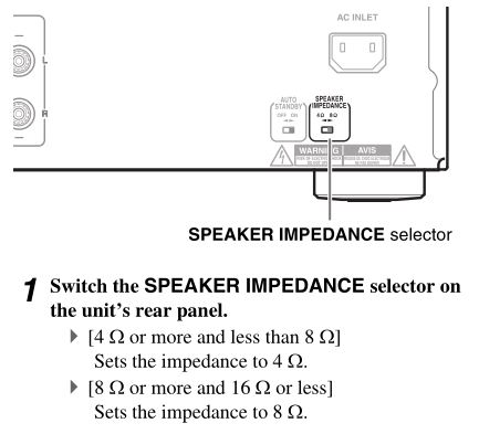
Caution
- Settings will not be enabled even when the selector is changed in the Standby mode.To change a setting, be sure to turn on the unit prior to making any changes.
Troubleshooting
First check the followings.Since the issue may be caused by other components that are connected, be sure to also check them while referring to their manuals.Further product operating procedures and FAQs (frequently asked questions) are available from the Onkyo web site. http://www.jp.onkyo.com/support/
Tip
- Before requesting repairsIf the integrated amplifier is no longer working or functioning, any issues may be resolved by resetting the microcomputer contained in the integrated amplifier to revert all settings to their defaults. Before requesting repairs, follow the procedure below to reset the microcomputer.With the integrated amplifier turned on, hold down DIRECT and press 8ON/STANDBY.

Power
Can’t turn on the Integrated Amplifier.• Make sure that the power cord is properly plugged into the wall outlet (➔ page 14).• Unplug the power cord from the wall outlet, wait 5 seconds or more, then plug it in again.
The Integrated Amplifier turns off unexpectedly.• When the protection circuit is activated (because of speaker short-circuit, overload, or over-current), the integrated amplifier enters Standby mode. Remove the source of the problem and turn the integrated amplifier back on.• Check that the switch on the back of the integrated amplifier is set to the correct setting ( ➔ page 25 ).• The settings are not enabled when the switch is changed during the Standby mode.To change a setting, be sure to turn on the unit prior to making any changes.
Audio
There’s no sound.• Make sure the integrated amplifier’s volume control is not set to minimum (➔ page 22).• Make sure the correct input source is selected (➔ page 23).• Make sure the integrated amplifier is not muted (➔ page 24).• Make sure the speakers are connected correctly ( ➔ page 12 ).• Check all connections and correct as necessary ( ➔ page 12 ).• While headphones are connected, the speakers output no sound (➔ page 24).• The integrated amplifier does not support digital formats other than PCM. Inputting a digital format other than PCM will cause loud noise.
The sound quality is not good.• Make sure the speaker cables are connected with the correct polarity (➔ page 12).• Make sure all audio connecting plugs are pushed in all the way (➔ page 14).• The sound quality can be affected by strong magnetic fields, such as those from a TV. Try moving any such devices away from the integrated amplifier.• If you have any devices that emit high-intensity radio waves near the integrated amplifier, such as a cellular phone that’s being used to make a call, the integrated amplifier may output noise.
Headphone output is intermittent or there’s no sound.• This may be due to dirty contacts. Clean the headphones plug. See your headphones’ instruction manual for cleaning information. Also, make sure that the headphones cable is not broken or damaged.
Audio performance• Audio performance will be at its best about 10 to 30 minutes after the integrated amplifier has been turned on and had time to warm up.• Using cable ties to bundle audio cables with speaker or power cables may degrade the sound quality, so refrain from doing it.• Depending on the country, the integrated amplifier may be polarity-sensitive. In this case, plug the power cord in a way that provides the best sound quality.• Install the integrated amplifier on a sturdy rack or shelf. Position it so that its weight is evenly dispersed on its four legs. Do not install the integrated amplifier in a place with vibration or an unstable location.• Plug the power cord into an AC wall outlet.
Onkyo Dock
There’s no sound.• Make sure that the Onkyo Dock is connected to the integrated amplifier properly.• Make sure that no video content is being played.• Reset the iPod.
Other• When the Auto Standby (ASb) function is activated, the power of the Onkyo Dock connected via u is automatically turned off (➔ page 25)
Can’t control properly by using the remote controller.• Make sure that the u cable is connected to the integrated amplifier correctly. Check that each device is connected correctly and that the RI MODE switch is set correctly (➔ page 17).
External Components
No sound is heard from a connected component.• Make sure the correct input source is selected (➔ page 23).• Make sure the analog audio cable is connected correctly (➔ page 14).
When the u interlock does not function properly• Check that each device is connected correctly and that the RI MODE switch is set correctly (➔ pages 15 to 17).• Check that the switch on the back of the integrated amplifier is set to the correct setting.• The settings are not enabled when the switch is changed during the Standby mode. To change a setting, be sure to turn on the unit prior to making any changes.• The connecting method may vary depending on the device that will be connected. Please refer to the RI connection section in the owner’s manual of the connected device.
The sound from turntable is distorted.• If your turntable has a built-in phono preamp, connect to other analog inputs such as LINE IN.• If your turntable does not have a built-in phono preamp, connect a turntable to PHONO (➔ page 19).• Make sure that the ground wire is connected. Otherwise, it may produce an audible hum and noise.
Remote Controller
The remote controller doesn’t work properly.• Make sure the batteries have been installed with the correct polarity (+/–) (➔ page 7).• Replace both batteries with new ones. (Do not mix different types of batteries or new and old batteries.)• The remote controller is too far away from the integrated amplifier, or there’s an obstacle between them (➔ page 7).• The integrated amplifier’s remote control sensor is being subjected to bright light (inverter-type fluorescent light or sunlight).• The integrated amplifier is located behind the glass doors of an audio rack or cabinet.
Onkyo is not responsible for damages (such as CD rental fees) due to unsuccessful recordings caused by the unit’s malfunction. Before you record important data, make sure that the material will be recorded correctly.
The integrated amplifier contains a microcomputer for signal processing and control functions. In very rare situations, severe interference, noise from an external source, or static electricity may cause it to lockup. In the unlikely event that this should happen, unplug the power cord, wait at least 5 seconds, and then plug it again.
Before disconnecting the power cord from the wall outlet, set the integrated amplifier to Standby.
If during idling the cover is too hot to touch, then ventilation needs to be improved.
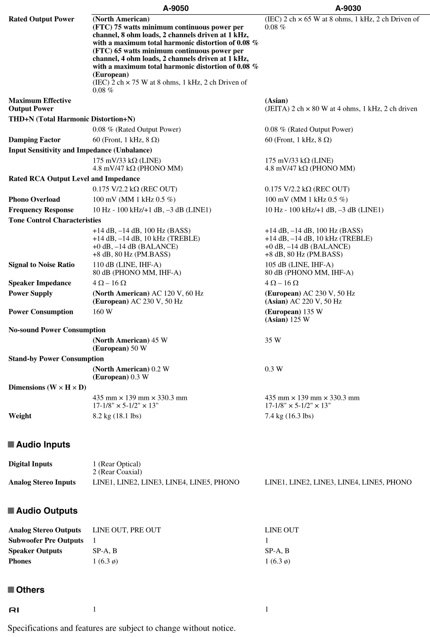
Specifications
![]()
2-1, Nisshin-cho, Neyagawa-shi, OSAKA 572-8540, JAPANhttp://www.onkyo.com/
The Americas18 Park Way, Upper Saddle River, N.J. 07458, U.S.A.For Dealer, Service, Order and all other Business Inquiries:Tel: 201-785-2600 Fax: 201-785-2650http://www.us.onkyo.com/
For Product Support Team Only: 1-800-229-1687http://www.us.onkyo.com/
EuropeLiegnitzerstrasse 6, 82194 Groebenzell, GERMANYTel: +49-8142-4401-0 Fax: +49-8142-4208-213http://www.eu.onkyo.com/
Meridien House, Ground floor, 69 – 71 Clarendon Road, Watford, Hertfordshire, WD17 1DS, United KingdomTel: +44 (0)8712-00-19-96 Fax: +44 (0)8712-00-19-95
ChinaUnit 1033, 10/F, Star House, No 3, Salisbury Road, Tsim Sha Tsui Kowloon, Hong Kong.Tel: 852-2429-3118 Fax: 852-2428-9039http://www.hk.onkyo.com/
1301, 555 Tower, No.555 West NanJing Road, Jing’an District, Shanghai, China 200041,Tel: 86-21-52131366 Fax: 86-21-52130396http://www.cn.onkyo.com/
Asia, Oceania, Middle East, AfricaPlease contact an Onkyo distributor referring to Onkyo SUPPORT site. http://www.intl.onkyo.com/support/
The above-mentioned information is subject to change without prior notice. Visit the Onkyo web site for the latest update.
SN 29401270B(C) Copyright 2013 Onkyo Corporation Japan. All rights reserved.

ONKYO A-9050/ A-9030 Integrated Amplifier Instruction Manual – ONKYO A-9050/ A-9030 Integrated Amplifier Instruction Manual –
[xyz-ips snippet=”download-snippet”]