ORATH Multi-Line Command Center
Installation Guide

![]()
Thank you for purchasing RATH’s Multi-Line Command Center. We are the largest Emergency Communication Manufacturer in North America and have been in business for over 35 years.
We take great pride in our products, service, and support. Our Emergency Products are of the highest quality. Our experienced customer support teams are available to remotely assist with site preparation, installation, and maintenance. It is our sincere hope that your experience with us has and will continue to surpass your expectations.
Thank you for your business,The RATH® Team

Command Center Options

Distribution Module Options
N56W24720 N. Corporate Circle Sussex, WI 53089800-451-1460 www.rathcommunications.com
Items Needed
Included
- Command Center phone with phone line cable
- Distribution Module
- System wiring (pigtail cables, power cord, Ethernet cable for programming the Distribution Module if needed)
- Cabinet (wall mount) or stand (desk mount)
Not Included
- 22 or 24 AWG twisted, shielded cable
- Multimeter
- Analog phone for troubleshooting
- Recommended: Biscuit jack for each phone(not applicable for elevator systems)
Pre-Installation Steps
Step 1Mount the Distribution Module and Power Supply with battery backup in an appropriate location, installing the Command Center for wall mount units or the stand for desk mount units accordingly, then remove the knock outs (if applicable). The recommended location to mount the Distribution Module and Power Supply is in a network closet or Machine Room. Mount the Command Center according to the owner’s specifications.
Follow the diagram below for attaching the extender and foot stand to the back of the Command Center phone as needed.
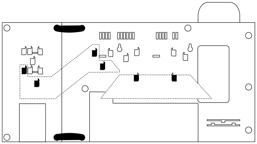
Step 2For 5-16 line systems, remove the screws on the back of the Distribution Module and remove the cover to expose the internal RJ45 interface connections.
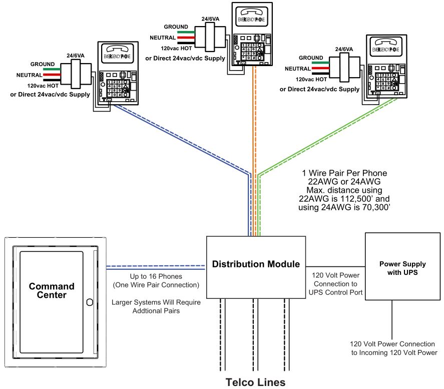
Typical System Layout
Distribution Module Wiring
Step 3
- These instructions apply for connecting the Command Center to the Distribution Module as well as for connectingEmergency Phones to the Distribution Module.
- The maximum cable run to the Distribution Module from the Command Center is 6,200′ for 22 AWG cable.
- The maximum cable run to an Emergency Phone is 112,500′ for 22 AWG and 70,300′ for 24 AWG cable.
- When connecting Emergency Phones to the Distribution Module, EIA/TIA Standards MUST be followed for wiring the locations to single pair 22 AWG or 24 AWG UTP twisted, shielded cable.
- The outbound CO lines are assigned to the respective SLT connections in the numbered order. For example, CO connection 1 is assigned to SLT connection 1.
Note: When using the Command Center for non-elevator applications, it is recommended to use a biscuit jack for connecting each phone. The communication wire pair should be connected to the red and green screw terminals on the biscuit jack. This will prevent loose connections that can cause the system to malfunction.
Option 15-16 Line System:
- On top of each RJ45 interface there is a label indicating connection:
- SLT is the port used for connecting elevator phones
- DKP is the port used for connecting Command Center phone(s)
- TWT is the port used for outside Telco lines
- Plug the supplied RJ45 pigtail cables into the RJ45 interface connections following the wiring chart and pin out color scheme on the next page.
- Refer to the top of the cards to see what type of RJ45 interface and number of extensions.
- The same pin-out color scheme should be used for the primary card and for all additional cards. The system uses T568-A for pin-out wiring.
- Each card installed in 5-16 line units will have three RJ45 interface connections.
- The first card installed will always be:
- Interface 1 (01-04): connection for up to 4 phones (SLT)
- Interface 2 (05-06): connection for up to 2 Telco lines (TWT)
- Interface 3 (07-08): connection for up to 2 Command Center phones (DKP)
- Each additional card is used for connecting phones and phone lines:
- Interface 1 (01-04): connection for up to 4 phones (SLT)
- Interface 2 (05-06): connection for up to 2 Telco lines (TWT)
- Interface 3 (07-08): connection for up to 2 Telco lines (TWT)

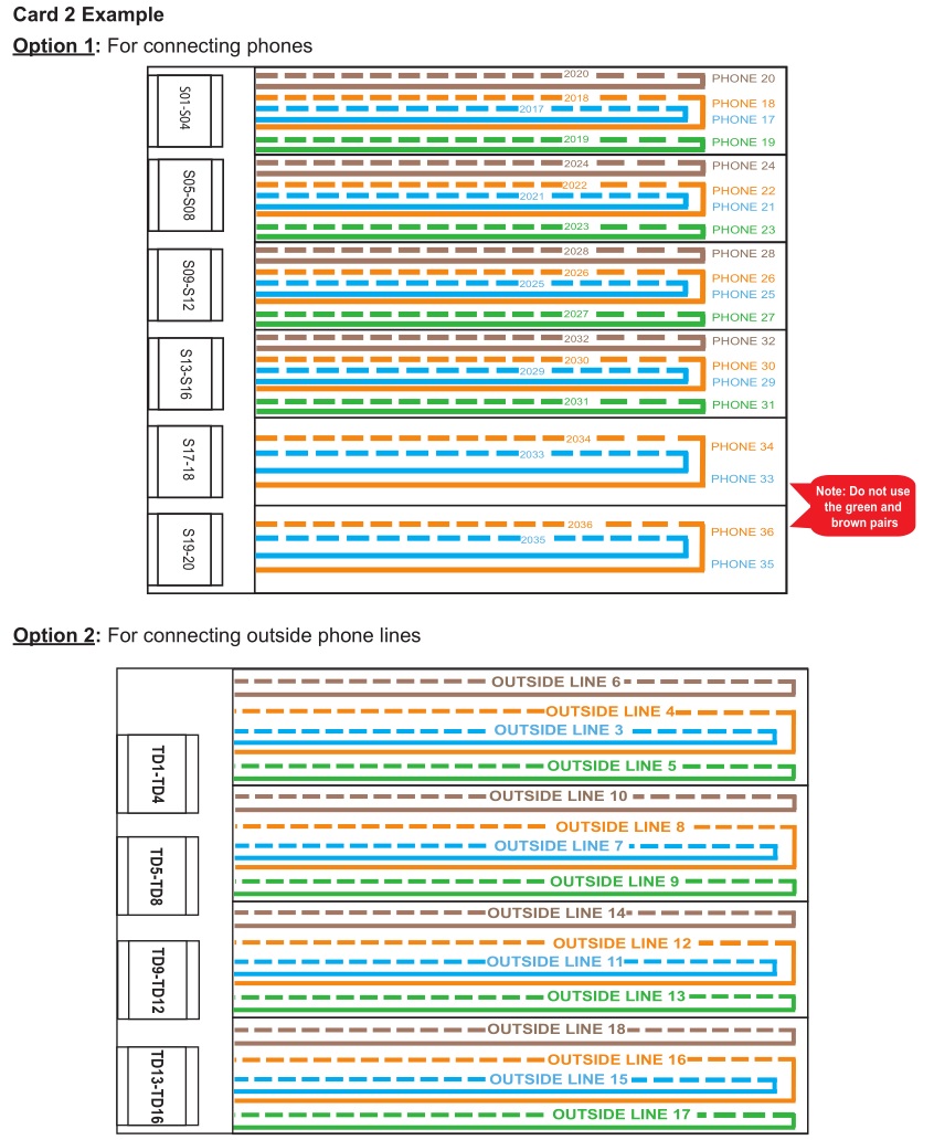
Option 217+ Line System:
- On top of each RJ45 interface there is a label indicating connection:
- S_ is the port used for connecting elevator phones
- TD(1-2)(3-4) with a dot under the D is the port used for connecting Command Center phone(s)
- TD(1-2)(3-4) with a dot under the T is the port used for outside Telco lines
- Plug the supplied RJ45 pigtail cables into the RJ45 interface connections following the wiring chart and pin out color scheme on the next page.
- Refer to the top of the cards to see what type of RJ45 interface and number of extensions.
- The same pin-out color scheme should be used for the primary card and for all additional cards. The system uses T568-A for pin-out wiring.
- Each card installed in 17+ line system will have six RJ45 interface connections.
- The first card installed will always be:
- Interface 1 (S01-S04): connection for up to 4 phones
- Interface 2 (S05-S08): connection for up to 4 phones
- Interface 3 (S09-S12): connection for up to 4 phones
- Interface 4 (S13-S16): connection for up to 4 phones
- Interface 5 (D1-2): connection for up to 2 Command Center phones
- Interface 6 (T1-2): connection for up to 2 Telco lines
- Each additional card is used for connecting phones:
- Interface 1 (S01-S04): connection for up to 4 phones
- Interface 2 (S05-S08): connection for up to 4 phones
- Interface 3 (S09-S12): connection for up to 4 phones
- Interface 4 (S13-S16): connection for up to 4 phones
- Interface 5 (S17-S18): connection for up to 2 phones
- Interface 6 (S19-S20): connection for up to 2 phones
- Or for connecting phone lines:
- Interface 1 (TD1-TD4): connection for up to 4 Telco lines
- Interface 2 (TD5-TD8): connection for up to 4 Telco lines
- Interface 3 (TD9-TD12): connection for up to 4 Telco lines
- Interface 4 (TD13-16): connection for up to 4 Telco lines

Step 4Apply AC power to the Distribution Module by connecting the supplied power cable from the Distribution Module to the RATH® model RP7700104 or RP7701500 Power Supply.
Step 5Turn on the Power Supply.
Setting the Date and Time
Step 6All Distribution Module programming will be done from the Command Center handset.
- Enter Program Mode
- a. Dial 1#91
- b. Enter Password: 7284
- Program the Time Zone
- a. Dial 1002 followed by the appropriate Time Zone code Eastern Time Zone = 111 Central Time Zone = 112 Mountain Time Zone = 113 Pacific Time Zone = 114
- b. Touch the GREEN button in the middle of the phone when finished
- Program the date (month-day-year format):a. Dial 1001 followed by the appropriate date (xx/xx/xxxx) Example: February 15, 2011 = 02152011b. Touch the GREEN button in the middle of the phone when finished
- Program the time (military time including hour-minute-second):a. Dial 1003 followed by the appropriate time (xx/xx/00) Example: 2:30 pm = 143000b. Touch the GREEN button in the middle of the phone when finished
- To exit Program Mode dial 00 followed by the GREEN button
Phone Programming
Step 7Option 1Emergency Phone calls a number outside the building:
- For the Phone to call a number outside the building, it must be programmed to first dial 9, Pause, Pause, then the phone number.
- Follow the directions that came with the Phone to program Memory Location 1 to dial 9, Pause, Pause, then the digits of the outside phone number.
Option 2Emergency Phone calls the Command Center first, then a number outside the building:
- The Phone can be programmed to call the Command Center first and, if that call is not answered, call an outside number.
- Follow the directions that came with the Phone to program Memory Location 1 to dial 3001, then program Memory Location 2 to dial 9, Pause, Pause then the outside phone number.
Note: Do NOT use “Ring Down” lines on multi-line systems.
Note: When using the location message feature on the Phone, it is recommended to add two pauses at the end of the programmed dialed number.
Example: For dialing the Command Center, program the Phone to dial 3001, Pause, Pause.
Testing
Step 8Once the installation and programming steps are complete, test each extension by placing a call to confirm the connections. If all testing is successful, replace the cover on the Distribution Module and secure with the provided screws (if applicable).
Command Center Operating Instructions
Indicator Status:
- Red LED Light = Incoming Call or Connected to Outside Party
- Blue LED Light = Active Call
- Blue LED Flashing = Call on Hold
Answering Call at Command Center:
- Lift handset to answer first incoming call
- Press Call Answer Button 1
- If multiple calls, press subsequent Call Answer Button 2, 3, etc. (this will place the previous calls on hold)
- To rejoin a call on hold, press the flashing blue LED next to the desired location
Joining a Call Already in Progress:
- Pick up the handset and press the red LED
- Listen for a busy tone
- Press the number 5 button on the numeric keypad
Disconnect Calls:
Option 1
- Hang up the handset to disconnect an active call
Option 2
- Select the blue flashing LED to take the call off hold
- Hang up the handset to disconnect the call (each call must be disconnected individually)
Calling a Location:
- Pick up the handset and press the desired location key (blue LED will light)
Call the Last Location that Dialed Out:
- Pick up the handset and dial 1092
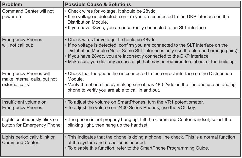
Troubleshooting
References
[xyz-ips snippet=”download-snippet”]